Page 634 of 1413
5. Install the airbag assembly with new TORXo bolts.
TORXO BOLTS10 N.m {1.0 kgf'm.7 lbf ftl
Disconnect the short connector trom the airbag con-
nector.
Connect the airbag 3-P connector and cable reel 3-P
connector.
Attach the short connector on the access panel. and
install the access panel on the steering lower cover.
CABLE REEI-CONNECTOR
7.
YELLOW GEAR TOOTH
ALIGNMENT MARK
10.
Connect the battery positive terminal and th€n con-
nect the nsgative terminal.
After installing the sirbag assembly, confirm proper
system opera(on:
. Turn the ignition to ll: the instrum€nt pan6l SRS
indicator light should come on for about 6 sec-
onds and then go off,
. Confirm operation of horn buttons.
. Confirm oDeration of cruise control sevresume
switches.
a Turn the steering wheel countetclockwise and
make su.e the yellow gear tooth still lines up
with the alignment mark.
17-27
Page 952 of 1413

Opening Drag Check
(Motor Removedl
Betore installing the motor, measure the etfort required
to open the glass using a spring scale as shown.
CAUTION: When using a spring scale, protoct the
leading edg6 ot th€ glass with a shop towel.
lf load is over 40 N (4 kgt, 9lbf). check side clearance
and glass height adjustment (see page 2O-78).
Closing Force Check
(Motor Installedl
1. After installing all removed parts, have a hetper hotd
the switch to close the glass while you measure
torce required to stop it. Attach a spring scale asshown. Read the force as soon as the glass siops
moving, then immediately release the switch andspnng scare.
CAUTION: When using a spring scale, protoct tho
leading odge ol th€ glass with a shop towel.
200-290 N(20 - 30 kgf, rt4- 66 lbf)
lf the force is not within specification, install a new
lock washer, adjust the tension by turning the mo-
tor clutch adjusting nut, and bend the lock washer
against the motor clutch adjusting nut.
LOCKWASHERReplace.
'r coul{TER-cLocKwrsETo decrease
GLASS
\
20-83
Page 959 of 1413

Moonroof
Opening Drag Check
(Motor Removed)
Before installing the motor. measure the effort required
to open the glass using a spring scale as shown
CAUTION: Whon using a spring scalo. protoct the
l€ading odge ol the glass with a shop tow€I.
lf load is over 40 N (4 kgl, 9lbt), check side clearance
and glass height adiustment (see page 20-85)'
Closing Force Check
lMotor Installed)
1. After installing all removed parts, have a helper hold
the switch to close the glass while you measure
force required to stop it. Attach a spring scale as
shown. Read the torce as soon as the glass stops
moving, then immediately release the switch and
spring scale.
CAUTION: When using a sp ng scala. protect th€
leading odge ol the glass with a shop towel'
Closing Force: 200-290 N
120-30 ksf. 44-66 lbf)
lf the lorce is not within specification, install a new
lock washer. adjust the tension by turnang the mo-
tor clutch adjusting nut, and bend the lock washe.
against the motor clutch adjusting nut.
GLASS
\
clocKwlsE /i 1 coutren-
To increase l, ctocKwlsE
torce, I Io decreaseforce
L.
20-90
--
Page 1004 of 1413
Clock rsmoval:
Caretully pry the clock at the left edge. then pull it out.Disconnect the connector.
CONNECTOR
tl
@
Glove box removal:
'1. Open the glove box.
2. Remove the screw, then remove the damper fromthe glove box.
3. Remove the screw, then remove the glove box.
: Bolt, scr6w locstions
A
: Bolt,
A
6
l^l
)P)
2 B<: Scrow, 1
CLOCK
4. Remove the damper and striker.
>: Nut, icrgw locations
A> : l{ut, 1 B
: Scrow, 2
,-.\'Flot]}lEl\+!lal
_ __,/ *' ,/
5. Installation is the reverse o{ the removal orocedure.
DAMPER
20-135
Page 1006 of 1413

Replacement
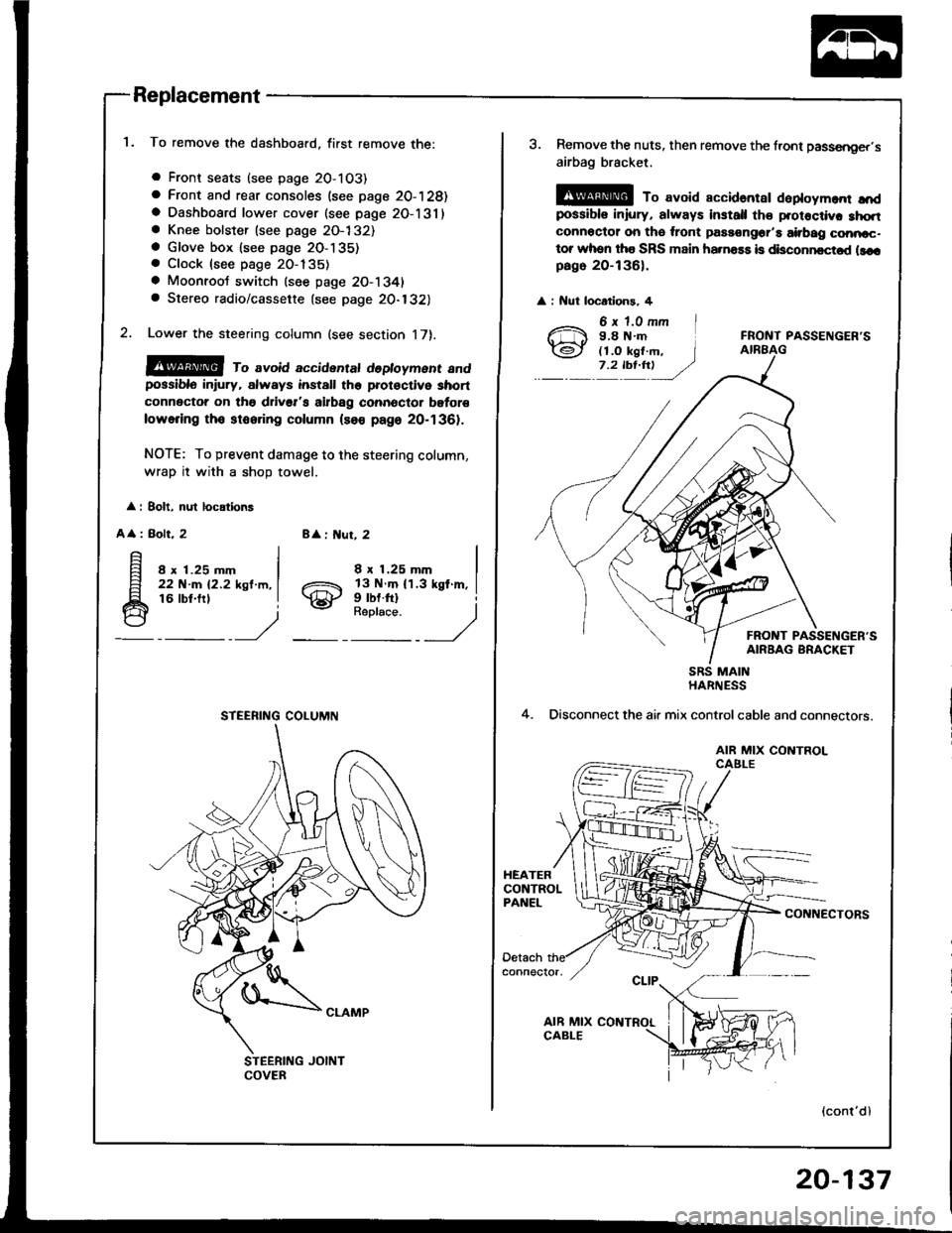
To remove the dashboard, first remove the:
a Front seats (see page 2O-103)
a Front and rear consoles (see page 20-128)a Dashboard lower cover (see page 2O-131)a Knee bolster (see page 2O-132)a Glove box lsee page 2O-135). Clock (see page 20-135)
a Moonroot switch (see page 20-1341a Stereo radio/cassette {see page 20-132)
Lower the steering column (see section 17).
@@ ro avoid accidentat dedoyment andpossiblo in ury, always install the prot€ctive short
connector on tho drivsr's airbag connector bgtor€
lowering tho stooring column (so€ page 20-1361.
NOTE: To prevent damage to the steering column,
wrap it with a shoD towel.
: 8olt, nul locations
A
: Bolt, 28 : ut, 2
8 x 1.25 mm22 N-m 12.2 ksl.m,16 lbt.frl
8 x 1.25 mm
gill$"'l
STEERING COLUMN
3. Remove the nuts, then remove the front passsnger,s
airbag bracket,
@ To avoid accidantar daploym.nr ",'dpossibls iniury, always install th€ protoctiv. 3hqtconnoctor on tho ,ront passongor'a airbag conncc-tor whon tha SRS main ha.na$ is disconncctod llcrpago 20-136).
: Nut locatlons, 4
FRONT PASSENGER'S
FRONT PASSENGER'SAIRBAG BRACKET
4.
SRS MAINHARNESS
Disconnect the air mix controlcable and connectors.
AIR MIX CONTROLCAELE
CONNECTORS
(cont'dl
20-137
Page 1028 of 1413
Hatch Spoiler
Replacement
a Take care not to scratch the hatch.a Open the hatch.
1. Remove the hatch side trim and hatch trim panel (seepage 2O-146).
2. Remove the nuts and disconnect the connector.
: Nut locations, 4
6 x 1.0 mm
Ch 9.8 N.m(J (1.0 ksl m, I__. 7,4b1!t ,/coI{t{EcroR
Remove the hatch spoiler by turning the clip nut onthe left side counterclockwise.
HATCH SPOILER
3. Installation is the reverse of the removal procedure.
Fender Well Trim and
Wheelhouse Protector
Replacement
a Take care not to bend the tender well trim.a Before installing the lender well trim, clean the bodvbonding surface with a sponge dampened in alcohol.a After cleaning, keep oil, g.ease or wafer lrom getlingon the surface.
> i Scr€w locations.
I
ADHESIVEFENDER WELLTRIM
20-159
Page 1138 of 1413

Connector ldentification and Wire Harness Routing
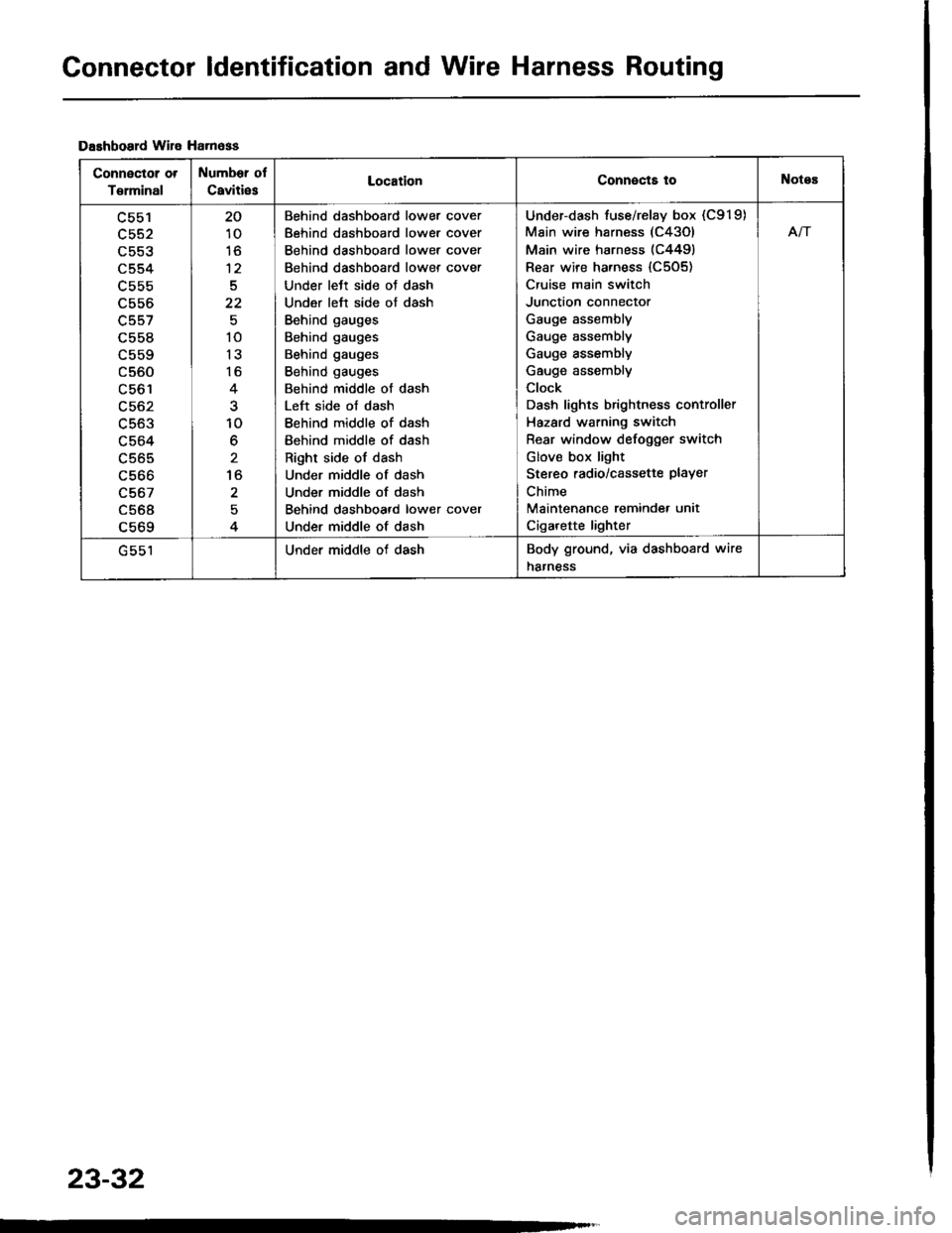
Dashboard wile Ha.n6ss
Connector ot
T€rminal
Number of
Caviti6sLocationConnects toNotes
c553
c554
L55b
c556
c557
c558
c560
LCO I
c563
c564
c565
c566
c567
c568a 6ACl
20
10
to
12
5
22
10
13
16
10
6
to
2
Behind dashboard lower cover
Behind dashboard lower cover
Behind dashboard lower cover
Behind dashboard lower cover
Under lett side oJ dash
Under left side of dash
Behind gauges
Behind gauges
Behind gauges
Behind gauges
Behind middle of dash
Left side of dash
Behind middle of dash
Behind middle of dash
Right side of dash
Under middle of dash
Under middle of dash
Behind dashboard lower cover
Under middle of dash
Under-dash fuse/relay box (C919)
Main wire harness (C43Ol
Main wire harness (C4491
Rear wire harness {C505)
Cruise main switch
Junction connector
Gauge assembly
Gauge assembly
Gauge assembly
Gauge assembly
Clock
Dash lights brightness controller
Hazard warning switch
Rear window defogger switch
Glov€ box light
Stereo radio/cassette PlaYer
Chime
Maintenance reminde. unit
Cigarette lighter
Afi
Under middle of dashBody ground, via dashboard wire
harness
23-32
Page 1155 of 1413

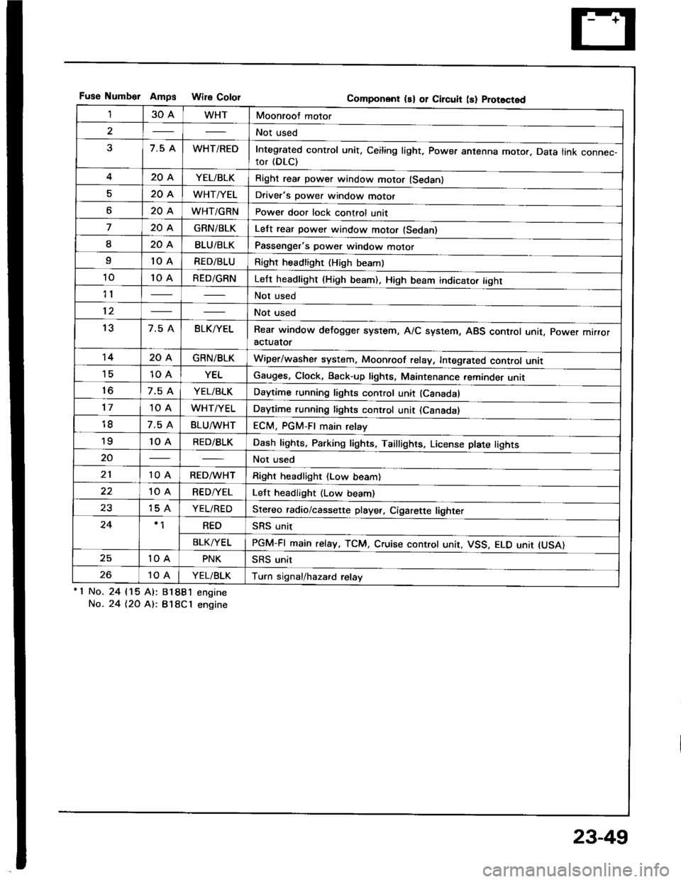
Fuse Numb€r AmDs Wire CololGomponent ls) or Circuit (s) Prot8cted
130AWHTMoonroof motor
2Not used
37.5 AWHT/REDIntegrated control unit, Ceiling light, Power antenna motor. Data link connec-tor (DLC)
420AYEL/BLKRight rea. power window motor (Sedan)
520AWHT/YELDriver's power window motor
o20AWHT/GRNPower door lock control unit
720AGRNiBLKLelt rear power window motor (Sedan)
I20ABLU/BLKPassenger's power window motor
I10 ARED/BLURight headlight {High beaml
1010 ARED/GRNLeft headlight (High beam). High beam indicato. tight
11Not used
12Not used
137.5 ABLK/YELRear window defogger system, A/C system, ABS control unit, power mrrroractuator
1420AGRN/BLKWiper/washer system, Moonroof relay, Integrated control unii'1510 AYELGauges, Clock, Back-up lights, Maintenance reminder unit
to7.5 AYEL/BLKDaytime running lights control unit (Canadal
1710 AWHT/YELDaytime running lights control unit (Csnada)
7.5 ABLU^tvHTECM, PGM-FI main relay'to10 ARED/BLKDash lights, Parking lights, Taillights, License plate tights
20Not used
2110 ARED/WHTRight headlight (Low beam)
10 ARED/YELLeft headlight (Low beam)
2315 AYEL/REDStereo radio/cassette player, Cigarette lighter
24REOSRS unit
BLK/YELPGM-FI main relay, TCM, Cruise controt unit, VSS, ELO unit IUSA)
2510 APNKSRS unit
2610 AYEL/BLKTurn signal/hazard relay'1 No.
No.
24 115 Al:
24 t2O At:.
81881 engine
B18Cl engine
23-49