Page 138 of 1413
7.Apply liquid gasket to the hesd mating surface of
th€ No. 1 and No. 5 camshaft holders on both the
intako and exhaust side. Confirm that the camshaft
koywEys face up, then place those holders, together
with th€ No.2, No. 3 and No.4 camshaft holders,
on th€ cylind6r head.
NOTE: The arrows msrked on the camshaft holders
should point to the timing belt.
INTAKE
t/
bl
ffi
rfl?x
rt
EXHAUST
Apply liquid gaskot
to lh6 3had€d aroas.
Temporarily tighton the bolts of tho camshaft hold-
6rs and thE camshaft holder plates,
lrlo. 6
d
ro
I
CAIISHAFT HOIDERS
Ho. a No.3 1to.2
rllttt
888
CAMSHAFT HOI,I'ER
9. Tighten the bolts in the sequence shown below.
(D - @: 8 x 1.25 mm 27 N.m {2.8 kgf.m,20 lbt ttl
(D - (D: 6 x 1.0 mm 9.8 N.m (1.0 kgrl.m, 7.2 lbf'ft}
10. Install the back cover and camshaft pulleys.
CAMSHAFT
ooooo0o
10 x 1.25 mm56 N.ln l5.t kgf.m,4r lbl.trl
6x1.0mm9.8 N.m 11.0 kgtm, t.2lbf'ft)
(cont'd)
6-77
Page 139 of 1413
11.
12.
13.
Cylinder Head
Installation lcont'd)
lnstallthe timing belt lsee page 6-51).
Adjust the valve clearance (see page 6-44).
Install the rubber seal in the groove of the cylinder
head cover. Seat the seal in the recesses for the
camshaft first, then work it into the groove around
the outside edges.
NOTE:
. Before installing the rubber seal. thoroughly
clean the seal and the groove.
. When installing, make sure the seal is seatedsecurely in the corners of the recesses with nogap.
COVER
6-78
14. Apply liquid gasket to the rubbe. seal at the eightcorne.s of the recesses.
NOTE:
. Use liquid gasket, Part No. 08718 - 0001.. Check that the mating surfaces are clean and dry
before applying liquid gasket.
a Do not install the parts if 20 minutes or more
have elapsed since applying liquid gasket.
Instead,.eapply liquid gasket after removing oldresidue.
r After assembly, wait at least 20 minutes beforefilling the engine with oil.
Apply liquid gasket tothe shaded areas.
Page 156 of 1413

Piston
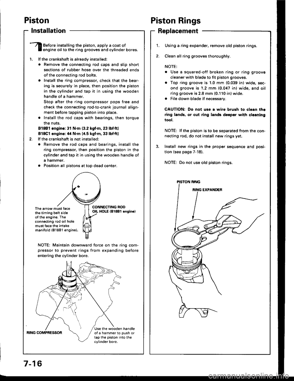
lnstallation
'1.
Before installing the piston, apply a coat ofengine oil to the ring grooves and cylinder bores.
lf the crankshaft is already installed:
. Remove the connecting rod caps and slip short
sections of rubber hose ove. the threaded ends
of the connecting rod bolts.
a Install the ring compressor, check that the bear'
ing is securely in place, then position the piston
in the cylinder and tap it in using the wooden
handle of a hammer.
Stop after the ring compressor pops free and
check the connecting rod-to-crank journal align-
ment before tapping piston into place.
. Install the rod caps with bearings, then torque
the nuts,
81881 ongino: 31 N.m {3.2 kgf.m, 23 lbf.ftl
818C1 cngino: 44 N'm 1,t.5 kgf.m, 33 lbf.ftl
lf the crankshaft is not installed:
o Remove the rod caps and bearings. install the
ring compressor, then position the piston in the
cylinder and tap it in using the wooden handle of
a nammer.
. Position all Distons at toD dead center.
CONNECTING RODOIL HOI-E (Br8Bl onginelThe arrow must facethe timing belt sideof the engine. Theconnecting rod oil holemust lace the intak€manifold {81881 €ngine).
NOTE: Maintain downward force on the ring com-
pressor to prevent rings from expanding before
entering the cylinder bore,
BING COMPRESSORUse the wooden handleof a hammer to push ortap the piston into thecylinder bore.
Piston Rings
Replacement
1.Using a ring expander, remove old piston rings.
Clean all ring g.ooves thoroughly.
NOTE:
. Use a squared-oJf broken ring or ring groove
cleaner with blade to fit piston grooves.
. Top ring groove is 1.0 mm (0.039 in) wide, sec-
ond groove is 1.2 mm (0.047 in) wide. and oil
ring groove is 2.8 mm (0.110 in) wide.. File down blade if necessary.
CAUTION: Do not use a wire brush to cloan thr
ring lands, or cut ring lands dsopo. with cl€aning
tool.
NOTE: lf the piston is to be separated from the con-
necting rod, do not install new rings yet.
Install new rings in the prope. sequence and posi-
tion (see page 7-18).
NOTE: Do not use old piston rings.
Page 159 of 1413

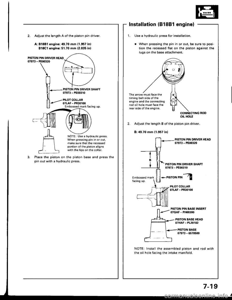
Installation (B18Bl engine)
2. Adjust the length A of the piston pin driver.
A:81881 engine:49.70 mm {1.957 inl
Bl8Cl €ngin€:51.70 mm {2.035 inl
PISTON PIN DRIVER HEAD07973 - PE00320
PISTON PIN DRIVER SHAFT07973 - PE00310
PILOI COLLAR07LAF - PR30100Embossed mark facing up.
NOTE: Use a hydraulic press.When pressing pin in or out,make sure that the recessedportion of the piston alignswith the lips on the collar.
Place the piston on the piston base and press the
pin out with a hydraulic press.
1. Use a hvdraulic oress for installation.
When pressing the pin in or out, be sure to posi-
tion the recessed flat on the piston against the
lugs on the base attachment.
The arrow must face thetiming belt side o{ theengine and the connectingrod oil hole must face therear side of the engine,
otl Hols
2. Adjust the length B of the piston pin driver.
B: 49.70 mm (1.957 inl
PISTON PIN DRIVER HEAD07973 - PEfl)320
PISTON PIN DR|VEN SHAFT079?3 - PE|X)310
Embossed mark
ffi*.r,"ror","l
PILOT COLLAN07LAF - PF301(x)
PISTON PIN BASE INSERT07GAF- PH603oO
PISTON BASE HEAD07HAF - PL20t02
PISTON BASE079?3 - 6570500
NOTE: lnstall the assembled piston and rod with
the oil hole facing the intake manifold.
7-19
Page 160 of 1413

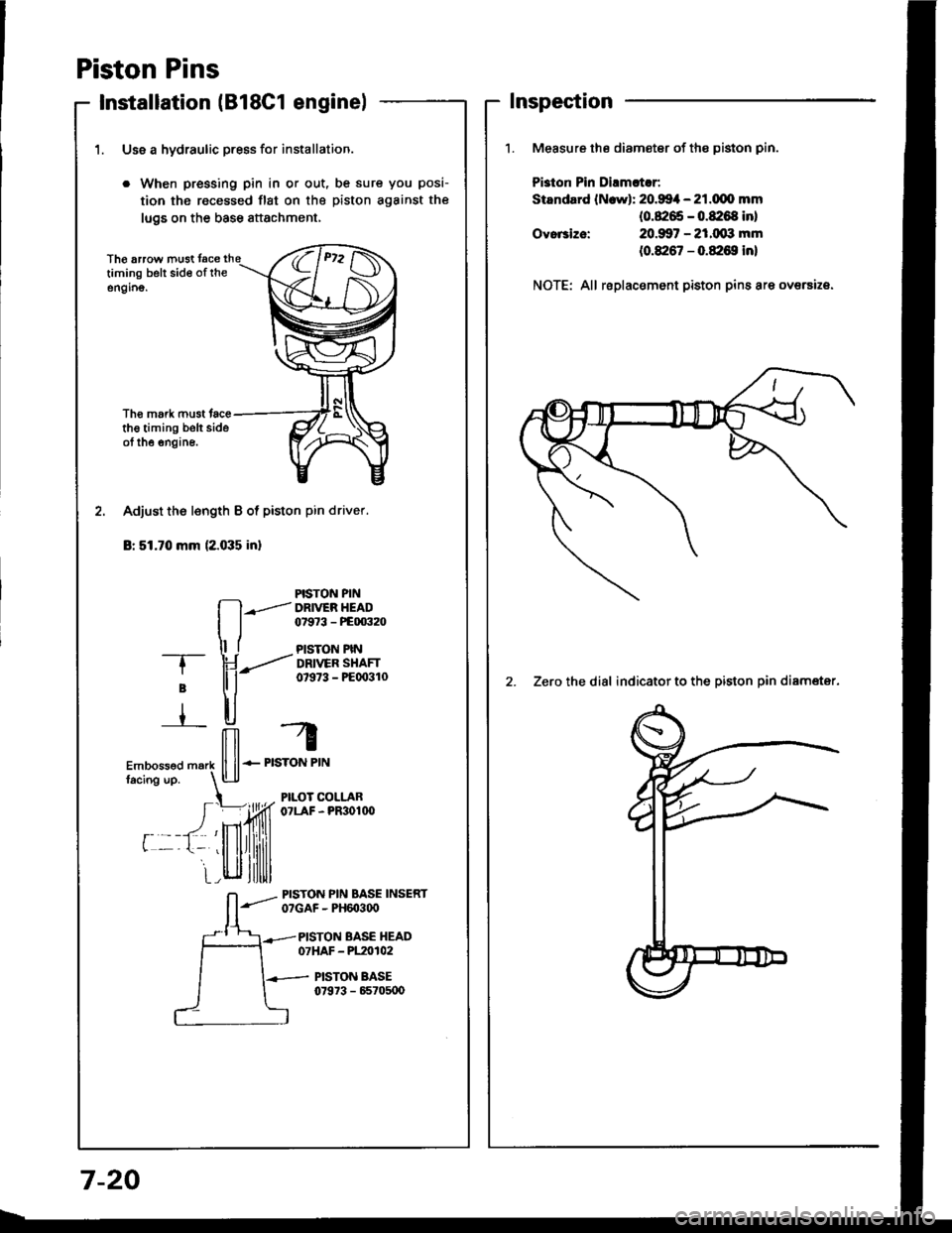
Piston Pins
Installation lB18C1 enginel
1. Use a hydraulic press for installation.
. When pressing pin in or out, be sure you posi-
tion the recessed flst on the piston against the
lugs on the base attachment,
Th€ arrow must tacetiming belt sid€ of rheengino.
Tho mork must tacethe timing belt sideot the engine.
PISTON PIN
fl--.l DRr
ER HEAD
I j 07e73 - PEm32o
ll t PlsroN PtN-T- \J ---..'' DRtvER sHAFr
; tl i- 07s73 - PEoo3lo
r ll-,H, -4
ilil r
Embossed m.rk ll ll-- PISTON PIN
facins up. l!-lJ
t PILOT COLLAR
I =)ffi o?LAF-PR3o1n'
r --t- 'llllrllilill
i_r_,llll,ltlllll
L-lt|lllltlll
Adjust the l€ngth B of piston pin driver.
Br 51.70 mm (2.035 inl
_- PrsroN PIN BASE INSERTO?GAF - PH6O3q)
PISTON BASE HEAD07HAF - P120102
PISTON BASE07973 - 65705U)
Inspection
Measure the diameter of the piston pin.
Pi3ton Pin Dirmltlr:
Standard lN.wl: 20.994 - 21.dlo mm(0.8265 - 0.8:168 inl
20.907 - 21.(xxt mm
(0.8267 - 0.&16S in)
Ovo.3ize:
NOTE: All replacement piston pins are oversize.
2. Zero the dial indicator to the piston oin diamater.
7-20
Page 176 of 1413
Oil Pump
5.
4.
Removal/lnspection/lnstallation
6. Remov€ the timing belt.
7. R€move the drive pulley.
8. Remov€ the oil pan and oil screen.
9. Remove the oil pump.
Drain the engine oil.
Turn the crankshatt and align the white groove on
the crankshalt pulley with the pointer on the lower
cover.
Remove the cylinder head cover and middle cover.
Remove the power steering pump belt, air condition-
er belt and the alternator belt.
Remove the crankshaft pulley and remove the low-
er cover.
OIL PUMP
OIL PAN
8-10
1O. Remove the screws trom the pump housing, thsn
separate the housing and coveJ.
1 1. Check the inner-to outer roto. radial clearance on thepumP rotor.
Innor Rotol-to-Outor Rotor Radial Cloaranco
StandErd (Newl: O.O4-O.16 mm(0.O02-0.006 in)
Service Limit: O.2O mm (0.008 inl
Check the housing-to-rotor axial clearance
pump rotor.
Housing-to-Botor Axial Claalanc€
Standard (Nowl: O.O2-O.O7 mm(O.OO1 -O.OO3 inl
Service Limit: O.15 mm (0.006 in)
on the12.
HOUSING
Page 193 of 1413
Inspection
Remove the timing belt (81881 engine: see page
6-1O, B18C1 engine: see page 6-49).
Check that the water pump pulley turns counter-
clockwise,
Check for signs ol seal leakage.
NOTE: A small amount ot "weeping" from the
bleed holo is normal,
BLEED HOLE
2.
J.
J.
Replacement
6 r 1.O rnm12 N.m {1.2 kgf.m,4.7 bf.ftl
4. lnstall the water pump in the reverse order
removat.
NOTE:
a Keep the O-ring in position when installing.
a Clean the spilled engine coolant.
Remove the timing belt (818B1 engine: see page
6-10,818C1 engine: see page 6-49).
Remove the camshaft pulleys and the back cover(81881 engine: see page 6-19. B18C1 engine: see
page 6-581.
Remove the water pump by removing five bolts,
NOTE: Inspect, repair and clean the O-ring groove
and mating su.lace with the cylinder block.
DOWEL PIN
BI-EED HOI-E
10-9
Page 583 of 1413

Differential (B18C1 enginel
Tapered Roller Bearing Preload Adjustment (cont'dl
7. It the tapered roller bearing preload is not within the
standard, select the 79.5 mm shim lrom the follow-
ing table which will give the tapered roller bea.ing
preload closest to the standard mean value of 2.50
N.m (25.5 kgJ.cm, 22 lbf.in).
NOTE: Changing the 79.5 mm shim to the next size
will increase or decrease tapered roller bearing
preload about O.3-O.4 N.m (3-4 kgf.cm,
2.6 - 3.5 lbt.in).
79.5 mm SHIM
Part NumbelThickness
41460-PY4-0000.66 mm (0.0260 in)
AB41461-PY4-0001.17 mm (O.0461In,
AC41462-PY4-0001 .2O mm (0.0472 in)
AD41463-PY4-0001.23 mm (O.O484 in)
AE41464-PY4-0001.26 mm (0.0496 in)
AF41465-PY4-OOO1.29 mm (O.O5O8 in)
AG41466-PY4-OOO1.32 mm (O.O52O in)
AH41 467-PY4-0001.35 mm {O.O531 in)
AI41468-PY4-0001.38 mm (O.O543 in)
AJ41469-PY4-0001 .41 mm (O.0555 in)
AK41470-PY4-OOO1 .44 mm (0.0567 in)
AL41 47 1 -PY 4-OOO1 .47 mm (0.0579 in)
AM41 47 2-PY 4-OOO1.50 mm {O.O591 in)
AN41473-PY4-0001 .53 mm (0.0602 in)
AO41 47 4-PY 4-OOO1.56 mm (0.0614 in)
AP41475-PY4-OOO'l .59 mm (O.0626 in)
AO4'1476-PY4-O001.62 mm (0.0638 in)
AR41 47 7 -PY 4-OOO1 .65 mm (0.0650 in)
AS41478-PY4-0001 .68 mm {0.0661 in)
41479-PY4-OOO1.71 mm (O.0673 in)
AU41480-PY4-OOO1.74 mm (0.0685 in)
41481-PY4-OOO1 .77 mm {0.0697 in}
41442-PY4-OOO1.80 mm (O.O7O9 in)
AX41483-PY4-OOO1.83 mm (0.0720 inl
15-16
9.
Recheck the tapered roller bearing preload.
How to select the correct 79.5 mm shim:- 1) Compare the tapered roller bearing preload you
get with the 79.5 mm shim that was removed
with the specified mean preload of 2.50 N.m(25.5 kgf .cm. 22 lbf.inl.-2) lf your measured tapered roller bearing preload
is less than specified, subtract your's from the
soecified.
lf your's is more than specified, subtract the
specified from your measurement.
For example with a 1 .38 mm (O.O543 in) shim:
@ specified 2.50 N.m (25.5 kgf.cm, 22 lbf.in)- you measure 0.54 N.m (5.5 kgt.cm, 5lbt'in)
2.0 N.m {20 kgf.cm, 18lbt.in} less
@you measure 3.29 N.m {33.5 kgl.cm, 29 lbl.in)- specified 2.50 N.m {25.5 kgf.cm, 22 lbf.in)
0.8 N.m (8 kgf.cm, 7lbt.in) more
3) Each shim size uD or down from standard
makes about O.3-O.4 N.m (3-4 kgf.cm,
2.6-3.5 lbf.in) difJerence in tapered roller
bearing preload.
a In example @, your measured tapered roller
bearing preload was 2.O N.m (20 kgf'cm,
I 8 lbl.in) less than standard so you need a
79.5 mm shim five sizes thicker thsn stan-
dard {trv the 1.53 mm (0.0602 inl shim and
recheck).
a In example @ your's was O.8 N.m (8
kgf.cm, 7 lbJ.in) more than standard, so
you need a thrust shim two sizes thinner (try
the 1.32 mm (0.0520 in) shim and recheck).
After adjusting the tapered .oller bearing preload, as-
semble the transmission, and installthe transmission
housing {see section 13).
8 x 1.25 mm
27 N.m 12.8 kgt.m. 20 lbf.ttl
Rotate the diJJerential assemblv in both directions
to seat the tapered roller bearings.
10.
11.