1994 HONDA INTEGRA belt
[x] Cancel search: beltPage 991 of 1413

Seat Belts
lnspection
Retractol InsDection
1. Before installing the retractor, check that the seat
belt can be pulled out freely.
2. Make sure that the seat belt does not lock when the
retractor is leaned slowly up to 150 from the mount-
ed oosition. The seal belt should lock when the
retractor is leaned over 4O".
CAUTION: Do
tgtractol.
Hatchback
Forwald -
Rear:
not attempt to disassemble the
' : Mounted Position
RETRACTOB
Iniid6
Sedan
Front:
Forwardlnsido
Forward
Rear:
RETRACTOR
3. Replace the seat belt with a new one if there is any
abnormality.
On-the-Cal S€at Belt Inspection
1 . Check that the seat belt is not twisted or caught on
anythrng.
After installing the anchors, check lor free movement
on the anchor bolts. lf necessary, remove the anchor
bolts and check that the washers and other pans are
not damaged or improperly installed.
Check the seat belts for damage or discoloration.
Clean with a shop towel iI necessary.
CAUTION: Use only soap and water to clean.
NOTE: Dirt build-up in the metal loops of the upper
anchors can cause the seat belts to retract slowly.
WiDe the inside of the loops with a clean cloth damp-
ened in isopropyl alcohol.
Check that the seat belt does not lock when pulled
out slowly. The seat belt is designed to lock only dur-
ing a sudden stop or impact.
Make sure that the seat belt will retract automata-
cally when released.
Replace the seat belt with a new one it there is any
abnormality.
2.
3.
4.
20-122
Page 993 of 1413
Garpet
Replacement
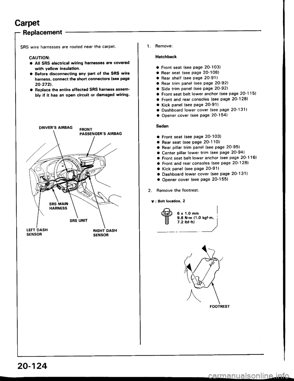
SRS wire harnesses are routed near the carpet.
CAUTION:
a All SRS slectrical wiring harn€ssos al€ covorod
with yollow insulation.
a Belore disconn€cting 8ny patt of th€ SRS wite
harness, connoct th€ short connectors {see pago
20-2721.
a ReDlace the €ntire affected SRS haln€sa assam-
bly if it has an opan cilcuit or damaged wiring.
ORIVER'S AIRBAG
1. Remove:
Hatchback
a Front seat (see page 2O-103)
a Rear seat (see page 20-108)
a Rear shell {see page 2O-91}
a Rear trim panel {see Page 20-921
a Side trim panel (see page 20-92)
a Front seat belt lower anchor (see page 20-115)
a Front and rear consoles (see page 2o-128)
. Kick panel (see page 2O-91)
a Dashboard lower cover (see page 20-131)
a Opener cover (see page 20-154)
Sedsn
a Front seat (see page 20-103)
a Rear seat {see page 2O-1 10)
a Rear pillar trim panel (see page 20-95)
a Center pillar lower trim (see page 20-94)
a Front seat belt lower anchor {see page 20- 1 1 6l
a Front and rear consoles (see page 20-128)
a Kick panel (see page 20-91)
a Dashboard lower cover (see page 20-131)
o Opener cover (see Page 20-155)
2. Remove the footrest.
V : Bolt locatios, 2
FOOTREST
20-124
I
v
6 x 1.O mm9.8 N.m {'l.o7 .2 tbt.ftl
Page 1016 of 1413
8.
o.
7.
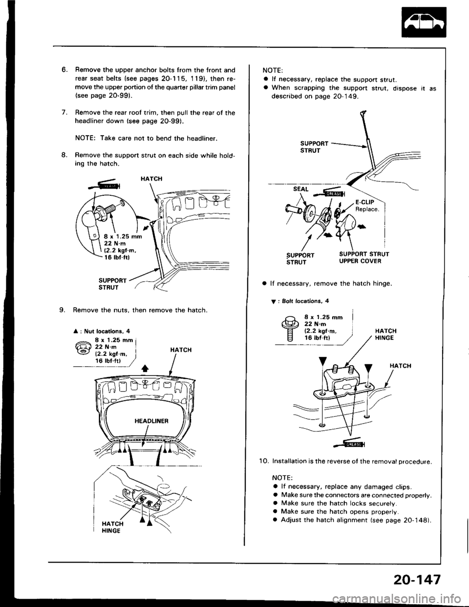
9. Remove the nuts, then remove the hatch.
a : Nut locations, 4
Remove the uDDer anchor bolts from the tront and
rear seat belts {see pages 20-1 1 5, 'l 19), then re-
move the upper portion of the quarter pillar trim panel
(see page 20-991.
Remove the rear roof trim, then pull the rear of the
headliner down (see page 2O-99).
NOTE: Take care not to bend the headliner,
Remove the support stfut on each side while hold-
ing the hatch.
SUPPORTSTRUT
HATCH
HATCH
I x 1.25 mm22Nm
12,2 kgt'm,16 tbt.ftl
12.2 kgl.m, I,6'y!:t ,/
NOTE:
a lf necessary, replace the support strut.a When scrapping the suppon $rut, dispose ir as
described on page 20-149.
a lf necessary, remove the hatch hinge.
V : Solt locdlions, 4
8 x 1.25 mm22 N.rn12.2 kgt.m,16 tbf.ft)HATCHHINGE
HATCH
1O. Installation is the reverse ot the removal procedure.
NOTE:
a lf necessary, replace any damaged clips.a Make sure the connectors are connected properly.
a Make sure the hatch locks securely.a Make sure the hatch opens properly.
a Adjust the hatch alignment (see page 20-148).
20-147
Page 1069 of 1413
Air Conditioning
*Evaporator
Repf acement .........22-26
Overhauf ................ 22-27
Compressor
Description ............ 22-28
fffustrated fndex ............................... 22-29
Replacement .........22-30
Cf utch lnspection ....................... ...... 22-32
Cf utch Overhaul ............................... 22-33
Ref ief Vaf ve Replacement ............... 22-34
A/C Compressor Belt
Repf acement .........22-35
Adiustment ............22-36
Condenser
Replacement ......... 22-37
A/C System Service
Evacuation ....,.......,22-38
Charging ................ 22-39
Leak Test ...............22-40
+: Read SRS precautions before working in
this area.
Page 1070 of 1413
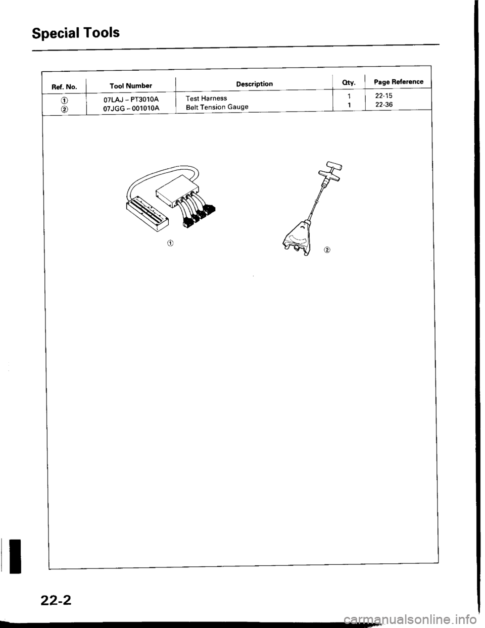
Special Tools
Ref. No. I Tool Numbel
Test Harness
Belt Tension GaugeOTLAJ - PT3O1OA
07JGG - 001010A
I
22-2
Page 1101 of 1413
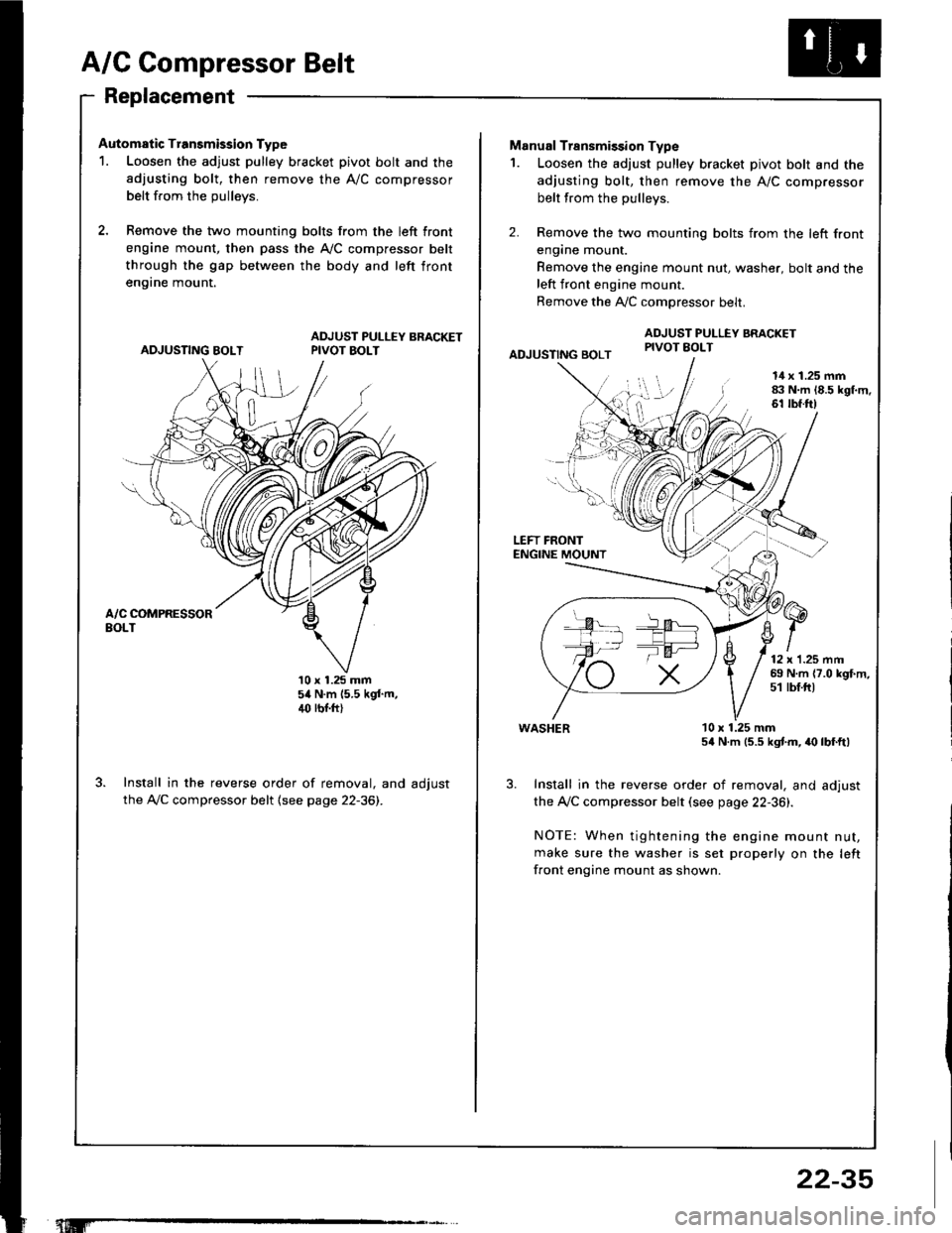
A/C Compressor Belt
Replacement
Automatic Transmission Type
1. Loosen the adjust pulley bracket pivot bolt and the
adjusting bolt, then remove the A/C compressor
belt from the oullevs.
2, Remove the two mounting bolts from the left front
engine mount, then pass the A,/C compressor belt
through the gap between the body and left front
en9rne mount.
ADJUSTING BOLTADJUST PULLEY BRACKETPIVOT BOLT
10 x 1.25 mm54 N.m (5.5 kgf.m,4(' rbr.ft)
Install in the reverse order of removal, and adjust
the A,/C compressor belt (see page 22-36).
"t.M'
22-35
-la ar-
Manual Transmission Type
1. Loosen the adjust pulley bracket pivot bolt and the
adjusting bolt, then remove the A/C compressor
belt from the pullevs.
2. Remove the two mounting bolts from the left front
engane mount.
Remove the engine mount nut, washer, bolt and theleft front engine mount.
Remove the A,./C comoressor belt.
ADJUSTING BOLT
ADJUST PULLEY BRACKETPIVOT EOLT
l!l',
I
14 x 1.25 mm83 N.m 18.5 kgl.m.61 tbf.ft)
LEFT FRONTENGINE MOUNT
12 x'1.25 mm69 N.m {7.0 kgf.m,51 tbf.ftt
WASHER
Install in the reverse order of removal, and adjust
the Ay'C compressor belt (see page 22-36).
NOTE: When tightening the engine mount nut,
make sure the washer is set properly on the left
front engine mount as shown.
10 x 1.25 mm54 N.m (5.5 kgtm, irc lbf.ft)
Page 1102 of 1413
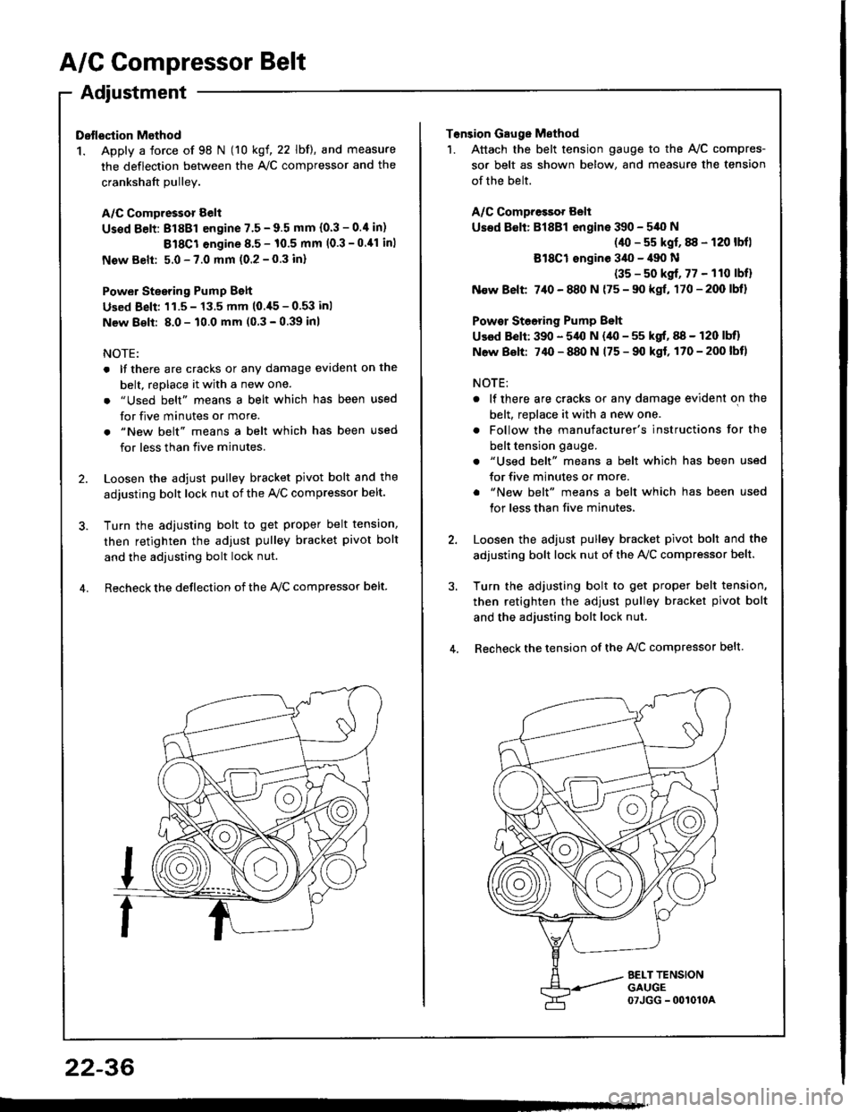
A/C Compressor Belt
Adjustment
Dstlsqtion Method
1. Apply a force of 98 N (10 kgf, 22 lbf), and measure
the deflection between the A,/C compressor and the
crankshaft Dullev.
A/C Compressor Belt
Us€d Eelt: 81881 engine 7.5 - 9.5 mm (0.3 - 0.4 in)
Bl8Cl engine 8.5 - 10.5 mm (0.3 -0.11 inl
New Belt: 5.0 - 7.0 mm (0.2 - 0.3 inl
Power Stesring Pump Belt
Used Beli: 'l1.5 - 13.5 mm (0.,[5 - 0.53 inl
New 8€lt: 8.0 - 10.0 mm (0 3 - 0.39 inl
NOTE:
. lf there are cracks or any damage evident on the
belt, replace it with a new one.
. "Used belt" means a belt which has been used
for five minutes or more.
. "New belt" means a belt which has been used
for less than five minutes.
2. Loosen the adjust pulley bracket pivot bolt and the
adjusting bolt lock nut of the Ay'C compressor belt.
3. Turn the adiusting bolt to get proper belt tension,
then retighten the adjust pulley bracket pivot bolt
and the adjusting bolt lock nut.
4. Recheck the deflection of the lvc compressor belt
22-36
Tonsion Gauge Method
1. Attach the belt tension gauge to the Ay'C compres-
sor belt as shown below, and measure the tension
of the belt.
A/C Compressot Belt
Used 8€lt: Bl8Bl engine 390 - 540 N
(40 - s5 kgf, 88 - 120 lbfl
Bl8Cl ongine 3il0 - il90 N
(35 - s0 kgf, 77 - 110 lbfl
N€w Belt 7,10 - 880 N {75 - 90 kgf, 170-200lbl}
Powor Steoring Pump Belt
Used Belt: 390 - 5,{l N (40 - 55 kgf, 88 - 120 lbll
N6w Bolt: 74O - 880 N 175 - 90 kgf, 170-200lbt)
NOTE:
. lf there are cracks or any damage evident on the
belt, replace it with a new one.
. Follow the manufacturer's instructions for the
belt tension gauge.
. "Used belt" means a belt which has been used
for five minutes or more.
. "New belt" means a belt which has been used
tor less than five minutes,
2. Loosen the adjust pulley bracket pivot bolt and the
adjusting bolt lock nut of the AVC compressor belt.
3, Turn the adjusting bolt to get proper belt tension,
then retighten the adjust pulley bracket pivot bolt
and the adjusting bolt lock nut.
4. Recheck the tension of the A{/C compressor belt.
Page 1107 of 1413

Electrical
Special Tools
Troubleshooting
Tips and Precautions ................................ 23-3Five-stop Tloubleshooting ..............,...-..-... Z3-sSchematic Symbols ................................_. 23-6wire Color Cod€s ..................................... 23-6Relay and Control Unit Locations
Engine Compartment .........,............ ... --. 23-7Dsshboard and Door ..,,......................... 23-gDashboard and Floor ............................. 23-t OOuaner Panel .....-.....23-12Connector ldentification and WireHarness Routing ........ 23-i 3
Index to Circuits and Systems
Airbag ............... ...-..-... 2g-26sAir Conditioning ....,.. Section 2lAltelnator ......_.............. 23-99Anti-lock Brake Systsm (ABS) Section 19Automatic Transmission Section 14Battery .............. .......... 23-66Chafging System ........... 23-98rCigalstte Lighter .....................-...-......-..-.. Z3-2O4Cfock ................. ..........23-197rcruise Controf .......--..-... 23-242Distributor .................... 23-87Fan Controls ................. 23-1ogFuel and Emissions ... Section 1i*Fuses
Under-dash Fuse/Relay Box ................... 23-48Undor-hood ABS Fuse/Retay Box ............ 23-51Under-hood Fuse/Relay Box,.................. 23-52rGauges
Engine Coolant Temperature {ECT)Gauge ................ ..23-126Fuef cauge ............... 2g-123'Gauge Assembly ....--.23-113Speedometer .....-...,,. 23-114Tachometer .....,.....-.. 23-114Ground Distribution ........ 23-60Heater ,,,........,.... ..... Section 2lrHorn ................. ........... 23-199*fgnition Switch ............. 23-70fgnition Syst6m .......-..-.. 23-A7lgnition Timing .............. 23-89Indicator Lights"A/T Gear Position .............. ................... 23-1 32B1ak6 System ...,..,..-.23-127Engine Oil Pressura .............................. _ 23-1 51Low Fuel ............ ......23-125Malfunction Indicator Lamp {MlL} ...,,. Section I l
tfnteglated Control Unit ...29-144*lnterlock System ...................................... 23-1 3gLights, Exteriol
Back-up Lights ........... 23-179Brake Lights .............. 23-t8ltDaytime Running Lights {Csnada} ........... 23-156Front Palking Lights ............................. 23-1 65Flont Side Marker Lights ....................... 23-165Front Turn Signal Lights ........................ 23-1 65*Hazard Warning Lights .........................- 2g-1A4Headlights ................. 23-t6tLicense Plate Lights .............................. 23-1 69Taillights(Harchback) .......... 23-166
{Sedan) .............. .. 23-167Lights. Inteliol
Cargo Area Light {Hatchback) ...... -.. -.. -... 23-177Ceifing Light ........-..-.23-175
Dash Lights Blightness Controt .............. 23-t70Glove Box Lighr ................................... 23-1 69Spotfighr ............ ....-.23-174Trunk Light (Sedanl ............... .............. - 23.-177*Lighting Sysrem .......-.-... 23-152:Moonroof ,,.,.......,..,,,,,.-.23-211PGM-FI Systom ........ S€crion 11Power Distribution .,.-..--..23-54Power Door Locks .............,,..................... 23-233Power Mirors ..,..,....-...- 23-216Power Relays ...........,..... 23-68Power Windows ............ 29-222*Rear Window Defogger ........,... ..........,..... - 23-20,6Reminder Systems
Key-in Remindel System ....,.............,.... 23-1 50Lights-on Reminder System ................... 23-l 5f*Maintenance Reminder system ..,,.... -.. - -. 23-.1 2gSeat Belt Reminder System ..................- 23-125*Side Markel/Turn Signal/Hazard
Ffasher System .,..,..-.23.-1A4Spark Pfugs .........-...-..... 23-97Starting System ....,,.....-. 23-73*Stereo Sound System ...,.......................,,.. 23-l gg
Supplemental Restraint System {SRS} ......... 23-265Vehicfe Speed Sensor {VSS) .............--..-.... 23-122*Wiper/Washer Systom ...............--.........-..- Zg-254
rRead SRS pi€cautions on Page 23-271 betore workingin these areas.
-+