Page 158 of 1413
Piston Rings
Alignment
1.Installthe rings as shown.
ldentify top and second rings by the chamfer on the
edge. Make sure they are in their proper grooves on
the prston.
NOTE: The manufacturing marks must be facing
upwaro.
TOP BING
OIL RINGSPACER
3. Position the ring end gaps as shown:
DO NOT position any ring gapsEcoNo R|NG GAp -.- :': :.-"' : - ' '----'-- { _- - - at prston thrust surfaces.
App.ox. 90"
OIL RING
ls" GAP
TOP BING GAPSPACER GAP
Rotate the rings
do not bind.
DO NOT position any ring gapin line with the piston pin hole.
SECOND RING
in their grooves to make sure they
MARK
OIL RING GAP
Piston Pins
Removal
1. Assemble the Piston Pin Tools as shown.
PISTO]T PIN BASE INSEN|T--r otGAF- PH6{t1,0
PISTON BASE HEAD
--l
PISTON BASE SP '{G07973 - 65r06{X'
7-18,
Page 162 of 1413

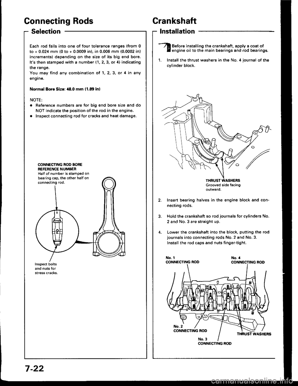
Connecting Rods
Selection
Each rod falls into one of four tolerance ranges (from 0
to + 0.024 mm (0 to + 0.0009 inl, in 0.006 mm {0.0002 in)
increments) depending on the size ot its big end bore.
It's then stamped with a number (1,2,3, or 4) indicating
the range.
You may find any combination ol 1, 2, 3, or 4 in any
engane.
Normsl Boro Sizoi ,18.0 mm 11.89 inl
NOTE:
a Reference numbers are Jor big end bore size and do
NOT indicate the position of the rod in the engine.
. Inspect connecting rod for cracks and heat damage.
CONNECNNG ROD BOREREFERENCE NUMBERHalf oI number is stamped onbearing cap. th€ other halfonconnecting rod.
Crankshaft
lnstallation
Before installing the crankshaft. apply a coat ofengine oil to the main bearings and rod bearings.
1. Install the thrust washers in the No. 4 iournsl of the
cvlinder block.
Grooved side tacingo!tward
Insert bearing halves in the engine block and con-
necting rods.
Hold the crankshaft so rod journals for cylinders No.
2 and No.3 are straight up.
Lower the crankshaft into the block. putting the rod
journals into connecting rods No.2 and No.3.
Install the rod caps and nuts finger-tight,
CONNECNNG ROD
7 -22
Page 163 of 1413

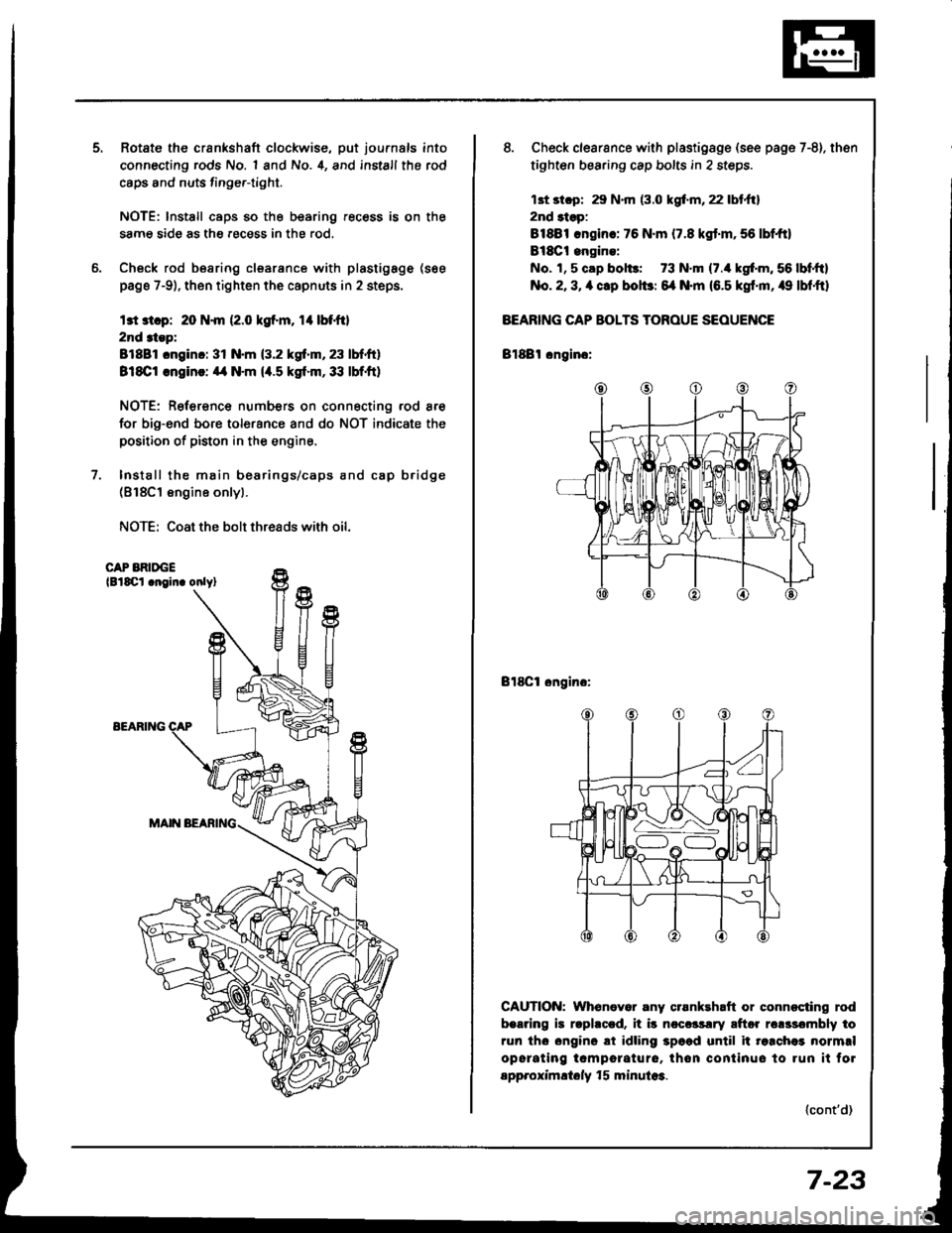
Rotate the crankshaft clockwise, put journals into
connecting rods No. 1 and No. 4, and install the rod
caps and nuts finge.-tight.
NOTE: lnstall caps so the bearing recess is on the
samg side as the .ecess in the rod.
Check rod bearing clsarance with plastigage (see
page 7-9), then tighten the capnuts in 2 steps.
l3t 3t.p: 20 N.m (2.0 kgf.m, rl btfil
2nd 3tep:
81881 cnginc: 31 N.m (3.2 kgf.m, 23 lbf.ft)
818C1 .ngin!: ,14 N.m (4.5 kgt.m,33 lbf.ft)
NOTE: Reference numbers on connecting rod are
for big-end bore tolorance and do NOT indicate the
positioo of piston in the engine.
Install the main bearings/caps and cap b.idge(818C1 engine onlyl.
NOTE: Coat the bolt threads with oil.
CAP BRIDGElBlSCl .noin. onlyl
EEARIlTG
8. Check clearsnce with plastigsge (see page 7-8). then
tighten bearing cap bolts in 2 steps.
13t st.p: 29 N.m (3.0 kgf.m, 22 lbt.ftl
2nd 3tsp:
81881 .ngin.: 76 N.m (7.8 kgt.m,56 lbf,ft)
Bl8Ct engine:
No. 1, 5 cap bol$: 73 N.m (7./r kgf'm, 56 lbf,ftl
No. 2, 3, a clp bolbr 6{ N.m (6.5 kgf'm, /r9 lbf,ftl
BEARING CAP BOLTS TOROUE SEOUENCE
Bl88l cngino:
Bl8Cl ongino:
CAUTION: Whenever any crsnkehaft or connocting rod
b.aring is rlphccd. it i5 ncccrsrry aftor rclssombly to
run tho ongino ai idling 3p6ad until it re.chei normrl
opcrating tcmporature, thon continuo to run it fol
spp.oximltoly f 5 minula3.
(cont'd)
7-23
Page 169 of 1413

lllustrated Index
DRATT PIUG \44 .m (4.5 tgf.m, 33 lbf'ftl \Do not ovgr tightgn. \-@5
OIL PAI{
6 r l.O mtn121{.m 11.2 kol.m,I lbl.ttl
CAUTIOIiI: Do not ovortighten the drain plug.
81881 sngine:
WASHERReplace.
O|L BNEATHERTAIIK
eq
nU2o@
\
u
I
#-'
GASKETR6placs,
NOTE;
o Use new O-rings when reassembling.
a Apply oil to O-rings betore installation,
. Use liquid gasket, Part No. O8718-OOO1.
a Clean the oil pan gasket mating surtaces before in-
stalling it.
6 x'l.o mm12 N.m {1.2 kgt.m, 9 lbt.tt)
6 x 1.0 mm'11 N.m 11 .1 kgt'm,8lbt.ftl
6 x 1.O mmll N.m {1.1 kgf'm,
OIL SCREEN
A
,F
HEAD OILCONTROL ORIFICECIean.
I tbt.ftl
OIL FILRepl.cemont, p6gs 8-6
ENGINE OIL PRESSUREswlTcH18 .m 11.8 kgl.m, 13lbl.ftl'l/8 in. BSP lgritish StandardPioo Taporl 28 Threads/inch.Use propgr laquid 56alant.
GASKETReplace.
BAFFLE PTATE
I x 1.25 mm24 N.m 12.4 kgf..n,17 rbr.ftl
6 x 1.O mm11 N-m (1.1 kgt.m,8lbf.ft)OIL PUMPOverhaul, page 8-9lnspection page, 8-1OApply liquid gasket toblock mating surlace.(cont'dl
8-3
Page 170 of 1413

lllustrated Index
(cont'dl
CAUTION: Do not overtighten rhe dlain ptug.
818C1 engine:
NOTE:
a Use new O-rings when reassembling.
a Apply oil to O rings before installation.. Use liquid gasket. Part No. 08718-OOO1.
a Clean the oil pan gasket mating surfaces before in-
stalling it.
OIL PAN
Replace.
6 x 1.0 mm12 N.m 11.2 kgl.m, 9 lbf.ftl
6 x 1.0 mm11 N.m 11.1 kgt.m,S lbf.fil
OIL JET BOLT16 N.m {'1.6 kgf.m, '13 lbf.ft}
OIL JETBe careful not to damage.Inspection, page 8-8
O-RINGReplace.
EAFFLE PLATE
6xl.0mm11 N.m (1.1 kgt.m, I lbt.ft)
OIL SCREEN
GASKETReplace.
6 r '1.0 mml1 N.m (1.18 rb-trlK9-m,
O-RINGReplace.
HEAD OIL CONTROLORIFICEClean.
8 x 1.25 mm24 N.m (2.4 kg-m, 17 lb-ft)ENGINE OIL PR€SSUREswtTcH1A N.m {1.8 kgf.m, 13 lbf.ft)1/8 in. BSP {British StandardPipe Taperl 28 threads/inch.Use proper liquid gasket.
OIL PUMPOverhaul, page 8-9Removal/lnspection/lnstallation, page 8-10Apply liquid gasket to matingsurface ot the engine block.
Il
,--)e6V
ENGINE OIL COOLER
ENGINE OIL FILTERReplacement, page 8-6
OIL COOLERCE TER BOLT74 N.m (7,5 kgf.m, 54 lbf.ft)
DRAIN PLUG44 N.m (4.5 kgf.m, 33 lbt.ftlDo not overtighten.
8-4
Page 175 of 1413
Oil Pump
Overhaul
NOTE:
a Use new O-rings when reassembling.
a Apply oil to O-rings before installation.
. Use liquid gasket, Part No. 08718-OO01.
a After reassembly, check that the rotors move without binding.
6 x 1.0 mm6 N.m 10.6 kgl.m, 4 lbt'ttl
OUTER ROTORInspection, pages I 10, 11O.RINGReplace.
0
6 x 1.O mm11 N.m (1.1 kgf.m,8 tbf.frl
DOWEL PIN
PUMP COVERInspection, page 8-10
INNER ROTORInspect|on,page 8-1 1
8 x 1.25 mm24 N.m (2.4 kgf.m,t7 tbt'ft)
\SPRING
OIL SEALInstallation, Page 8-1 1Replace.
RELIEF VALVEValve must slide treelyin housing bore.Replace when scored.PUMP HOUSINGlnspection, pages 8-10, 11Apply liquid gasketto mating suface oIthe cylinder blockwhen installing.*\
8 x 1.25 mm24 N.m (2.4 kgl.m,17 lbl.Irl
SEALING BOLT39 N'm 14.0 kgf.m,29 tbt.ttt
Page 180 of 1413
Intake Manifold
Replacement
NOTE: Use new O-rings and gaskets when reassembling.
CAUTION: Check for tolds or scratches on the aurface ot the gasket. Roplace with a now gasket it damagod,
81881 engine:
5r0.8mm6 N'm {0.6 kgl.m.4 rbr.ftlINTAKE AIRTEMPERATUREIIATI SENSOR
'*o*ot'u""'""N
5xO.8mm6 .m (0.6 kg{.m.4 tbf.ftl
O-RINGReplace.
IiITAKE MANIFOLDReplace iI cracked orit mating s!rtaces arodamag€o.
PURGE CONTROLSOLENOID VALVE
8 x 1.25 mm22 N.r 12.2 kgl.m,'16 tbt.ftt
IDLE AIR
GASKETSReplace.
I x 1.25 mm20 N.m (2.0 kgt.m.14 rbf.ftl
O.RINGReplace.{IACI VALVEBe careful notto damage.THROTTLE
8 x 1.25 mm
BODY
O-RINGSBeplace.
24 N.m (2.4 kgf'm,17 rbf.ft)
8 x 1.25 mm23 N.m (2.3 kgl.m,17 lbf.frl
BRACKET"o
aYc
g
/
1.25 mmN.m (2.4 kgl'm,rbf'ft1
8x2417
8 x 1.25 mm24 N.m (2.4 kgl'm.17 tbr.ftlTHERMOVALVE8e careful not todamage.
9-2
Page 181 of 1413
NOTE: Use new O-rings and gaskets when reassembling.
CAUTION: Chock for folds 01 scratches on th6 surfac6 of tho gaskot. Replace wilh a new gasket if damaged.
818C1 engino:
INTAKE MANIFOLDReplace il cracked oril mating surfaces are
5 x O.8 rnm6 N.m 10.6 kgl.m,4 tbt.ttl
lI
{,/
?,/
EVAP PURGE CONTROLVALVEdamageo.
IAT SENSOR
5xO.8mm6 N.m 10.6 kgf.m,4 tbf.ftl
INTAKE AIRBYPASS VALVE
IAC VALVEBe carelul notlo oamage.
O.RINGSReplace.
GASKETSReplace.
O.BI GReplace.
BODY
INTAKE MANIFOLDCHAMBER
8 x 1.25 mm23 N.rn 12.3 kgt'm,17 tbf.frl
I x 1.25 mm22 N.m 12.2 kgl.ft,t6 tbt.tt)
BRACKET
8 r 1.25 mm24 N.m {2.4 kgf.h,t7 rbr.ftl
8 x t.25 mfi24 N.m (2.4 lgf.m.17 tbt.ft)I r 1.25 lnm24 N.m 12.4 kgt.m,17 tbt.ftl
8 x 1.25 mm20 .m (2.0 kgt.m,14 tbf.ftl
THROTTLEAODY
FAST IDL€ THERMO VALVEBe carelul not to damage.
HEATER BYPASSPIPE
o-Rt GsReplace.
I x 1.25 mm24 N.m (2.4 kgl.m, 17lbf'ft|
9-3