Page 95 of 1413

Cylinder Head/Valve Train
818C1 engine
Special Tools ............. 6-34
wEc
Troubleshooting Flowchart
WEC Solenoid Valve ................... 6-36
VTEC Pressure Switch ................. 6-38
VTEC Solenoid Valve Inspection .... 6-41
Rocker Arms
Manual Inspection .....,................. 6-42
Inspection Using Special
Tools ....................................,.....,.. 6-/|i|
Valve Glearance
Adiustment ............ 6-44
Timing Belt
lllustrated 1ndex ............................... 6-46
Inspection .............. 6-48
Tension Adiustment ........................ 6-48
Removal ................. 6-4{l
lnstallation ............. 6-51
Crankshaft Pulley Bolt
Replacement .........6-47
Cylinder Head
lllustrated Index ............................... 6-53
Removal .................6-55
Warpage ................6-74
lnstallation ............. 6-75
Rocker Arms
Removal ................. 6-60
Location ................. 6-61
lnspection .............. 6-62
Arm-to-Shaft G|earance .................. 6-63
Installation ............. 5-64
Camshafts
Inspection .............. 6-65
Valve Guides
Valve Movement .............................. 6-70
Replacement .........6-71
Reaming ................. 6-72
Valve Seals
Reconditioning ......6-73
Valves. Valve Springs and Valve Seals
Removal ................. 6-67
lnstallation Sequence ..........,.......,... 6-69
Valve lnstallation ............................. 6-70
Page 114 of 1413
Cylinder Head
lllustrated Index
CAUTION: To svoid dsmaging the cylindor h.ad, wsit until tho engino coollnt tomper.turo drop3 bolow 100'F (38'C)
bofore romoving it.
NOTE:
r Use new O-rings and gaskets when reassembling.
. Use liquid gasket, Pan No. 08718 - 0001.
. Replace the rubber seals for oil leakage between the cylinder headand cover.
fterw ,o reassembling, clean all the parts in solvent, dry them, and apply lubricant to any contact parts.
6x1.0mm9.8 N.m (1 .0 kgt'm,7.2tblftl6xl.0mm9.8 N.m {1.0 kgl m, 7.2 lbf.ftl
4qis
CAMSHAFT
f,
f
6 x 1.25 mm2it t*m 12.4 kg[.m,17 rbf.ftl
8 x 1.25 mm27 N.m 12.8 kgt m,20 rbt ft)
CYLINDER HEADCOVERRefer to psge 6-78when instglling.
liquid gasketto thos€ points.INTAKECAMSHAFT
SEALReplace.Replace when damagedor det€riorated,
r 1.25 mm56 N.m 15.7 kg{.m,ial lbf.ft)
Replace.
6-53
Page 125 of 1413
Rocker Arms
Installation
1. Install the rocker arms in the reverse order ofremoval:
. Valve adjusting locknuts should be loosened andadjusting screw backed off before installation.. The component parts must be reinstalted in theoriginal locations.
2. Installthe lost motion assemblies.
3. Install the rocker arms while insening the rockerarm shaft into the cvlinder head
NOTE: Remove the rubber band after installing therocKer arms.
'/'/
12 mm EOLT
4.Clean and install the rocker shaft orifices with newO-rings. lf the holes in the rocker arm shaft andcylinder head are not in line with each other, screwa 12 mm bolt into the rocker arm shaft and rotatethe shaft.
NOTE: The shapes of the rocker shaft orifices forthe intake and €xhaust are different. The orificesmust be installed in the original locations.
INTAKE ROCKERSHAFT ORIFICEClean.EXHAUST ROCKERSHAFT ORIFICECl6an.
O.RINGBeplace.
Beplace.
6-64
Page 128 of 1413
Valves, Valve Springs and Valve Seals
Removal
NOTE: ldentify valves and valve springs as they are
removed so that each item can be reinstalled in its orioi-
nal position.
1. Using an appropriate-sized socket and plastic mal-
let. lightly tap the valve retainer to loosen the valve
keepers before installing the valve spring compres-
sor.
Install spring compressor. Compress spring and
remove valve keeper.
VALVE SpRtNG VALVE SPRING
COMPRESSoR COMPRESSoR ATTACHMENT
ATTACHMENT EXTENSION
(cont'd)
Snap-on CFrll
6-67
Page 129 of 1413
Valves, Valve Springs and Valve Seals
Removal (cont'dl
3. Installthe specialtool as shown
COMMERCIALLY AVAILABLEVALVE GUIDE SEAL REMOVERLrst"E P/N s79(x' OR KD3350
4. Remove the valve guide seal.
6-68
Valve Dimensions
lntrko ValYo
A Standsrd (N.wl: ilil.go - *t.10 mm(1.295 - 1.303 inl
B Standard (Newl: 101.00- 101.30 mm(3.976 - 3.988 inl
C Standard (N.w): 5.a75 - 5.185 mm(0.2156 - 0.2159 inl
C Sorvicc Limit 5.i!15 (0.21.lt in)
D Standard (Ncw): 1.05 - 1.35 mm(0.04i - 0.05:t in)
D Sorvicc Limh: 0.85 mm (0.033 inl
Exhau3t Valve
A Stand.rd (Ncwl 27.90 - 28.10 mm
11.098 - 1.106 inl
B Standard (Ncwl: 1qr.6lt - loo.glt mm(3.961 - 3.972 inl
C St.nd.rd (Now| 5./L51, - 5.460 mm(0.2146 - 0.215|, inl
C Servico Limit: 5.a20 (0.2134 inl
D Standsrd lNewl: 1.65 - 1.95 mm
{0.065 - 0.077 inl
D Sorvicc Limit 1.45 mm (0.057 inl
Page 131 of 1413

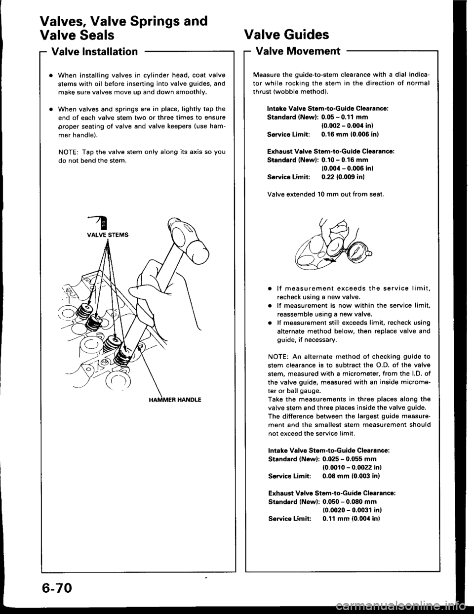
Valve lnstallation
When installing valves in cylinder head, coat valve
stems with oil before inserting into valve guides, and
make sure valves move up and down smoothly.
When valves and springs are in place, lightly tap the
end of each valve stem two or three times to ensure
proper seating of valve and valve keepers (use ham-
mer handle).
NOTE: Tap the valve stem only along its axis so you
do not bend the stem.
Valves, Valve Springs and
Valve SealsValve Guides
Valve Movement
Measure the guide-to-stem clearance with a dial indica-
tor while rocking the stem in the direction of normal
thrust (wobble method).
lntaks Valvr Stom-to-Guide Clearance:
Standard (Newl: 0.05 - 0.11 mm
{0.002 - 0.OO'l in)
Ssrvice Limit: 0.16 mm (0.006 in)
Exhaugt Vdve Stem-to-Guide Clsarancg:
Standald lNowl: 0.10 - 0.16 mm
(0.00'l - 0.006 in)
Sorvics Limit: 0.22 {0.0m in)
Valve extended 10 mm out from seat.
. lf measurement exceeds the service limit.
recheck using a new valve.
. lf measurement is now within the service limit,
reassemble using a new valve.
. lf measurement still exceeds limit, recheck using
alternate method below, then replace valve and
guide, if necessary.
NOTE: An alternate method ot checking guide to
stem clearance is to subtract the O.D. of the valve
stem. measured with a micrometer, from the l.D. ot
the valve guide, measured with an inside microme-
ter or ball gauge.
Take the measurements in three places along the
valve stem and three places inside the valve guide.
The difference between the largest guide measure'
ment and the smallest stem measurement should
not exceed the service limit.
lntafte Valvs Stom-to-Guida Clearance:
Stardard (Nowl: 0.025 - 0.055 mm(0.0010 - 0.0022 inl
Service Limit: 0.08 mm (0,003 in)
Exhaust Valvo Stem-to-Guide Clearance:
Standard lNew): 0.050 - 0.080 mm
10.0020 - 0.0031 in)
S€rvics Limit: 0.11 mm {0.0oil inl
6-70
Page 141 of 1413

Engine Block
Speciaf Tools .............7'2
lllustrated Index ................................... 7-3
Flywheel and Drive Plate
Repfacement .........7-7
Main Bearings
Clearance ,.............. 7-8
Selection ................ 7-8
Connecting Rod Bearings
Clearance ............... 7-9
Selection ................ 7-9
Crankshaft
Removal .................7-10
End Play .................7-12
lnspection ........,,,.,,7-12
fnstallation .............7'22
Cylinder Block
Inspeetion ..............7-13
Bore Honing .....,.,,.7'14
Pistons
Inspaction ..............7-15
Installation .............7-16
Piston Rings
Replacement .........7-16
End Gap .................7-17
Ring-To-Groove C|earance,,,,.,,,...... 7 -17
Alignment ..............7-18
Piston Pins
Removal ........,........7-18
Installation (818B1 engine) ............. 7-19
fnstaffation (818C1 enginel ............. 7-20
fnspection ..............7-2O
Connecting Rods
End Play .................7-21
Sefeetion ..........,,,,,,7-22
Oil Seal
fnstaffation .............7-25
Installation
(engine removal not requiredl.. .......7-26
Page 143 of 1413

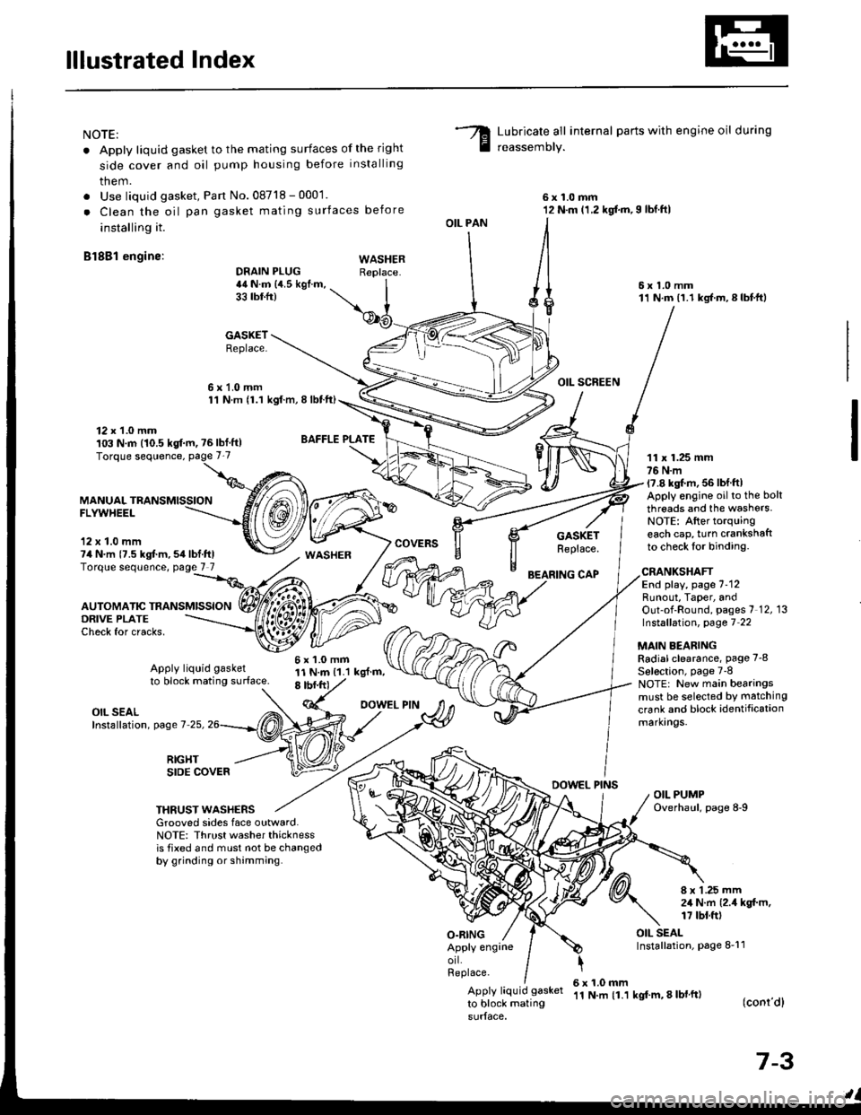
lllustrated Index
NOTE:
. Apply liquid gasket to the mating surfaces of the right
side cover and oil pump housing before installing
them.
. Use liquid gasket, Pan No.08718 - 0001.
. Clean the oil pan gasket mating surfaces before
installing it.
Bl8Bl engine: wAsHEF
Lubricate all internal parts with engine oil during
reassemory.
6x1.0mm12 N.m (1.2 kgf.m,I lbf.ftl
6x1.0mm11 N.m (1.1 kgf.m,8lbtft)
OIL SCREEN
11 x 1.25 mm76 N.m17.8 kgl.m, 56 lbf ftlApply engine oilto the bolt
threads and the washers.NOTE: After torquingeach cap, turn crankshaftto check lor binding.
DRAIN PLUG44 N.m {4.5 kgf.m,33 tbtfr)
GASKETReplace.
6x1.0mm1'l N.m {1.1 kgt.m, I lbtft)
OIL PAN
O.RING
GASKETReplace.
BEARING CAP
12 x 1.0 mm103 N.m (10.5 kgf.m, ?6lbf ft)
MANUALFLYWHEEL
'12 x 1.0 mm74 N.m {7.5 kgt m,54lbf.ftlTorque sequence, page 7 7
DRIVE PLATECheck for cracks,
AUTOMATIC TRANSMISSION
WASHER
6x1.0mm11 N.m {1.1 kgl.m,8 tbf.frt
CRANKSHAFTEnd play, page 7-12Runout, Taper, andOut-of-Round, pages 7 12, 13Instsllation, page 7 22
MAIN BEARINGRadial clearance, page 7-8
Sel€ction, page 7-8NOTE: New main bearingsmust be selected by matching
crank and block identificationmarkrngs.
Apply liquid gasket
to block mating surface.
OIL SEALInstallation, page 7-25,
RIGHTSIDE COVERDOWEL PINSOIL PUMPOverhaul, page 8-9THRUST WASHERSGrooved sides face outward.NOTE: Thrust washer thicknessis tixed and must not be changedby grinding or shamming.
8 x 1 .25 mm2,1 N.m {2.4 kgt m,17 tbt.ft)
OIL SEALInstallation, page 8-11Apply engrneorl.Replace.
Apply liquid gasket
to block mating
6x1.0mm'11 N.m {1.1 kgf'm, 8 lbl ft)(conr'dl
7-3