Page 1100 of 1413

and com
it with a
a
a
a
a
4t l\-N
r-
-l/
Compressor
Clutch Overhaul (cont'dl
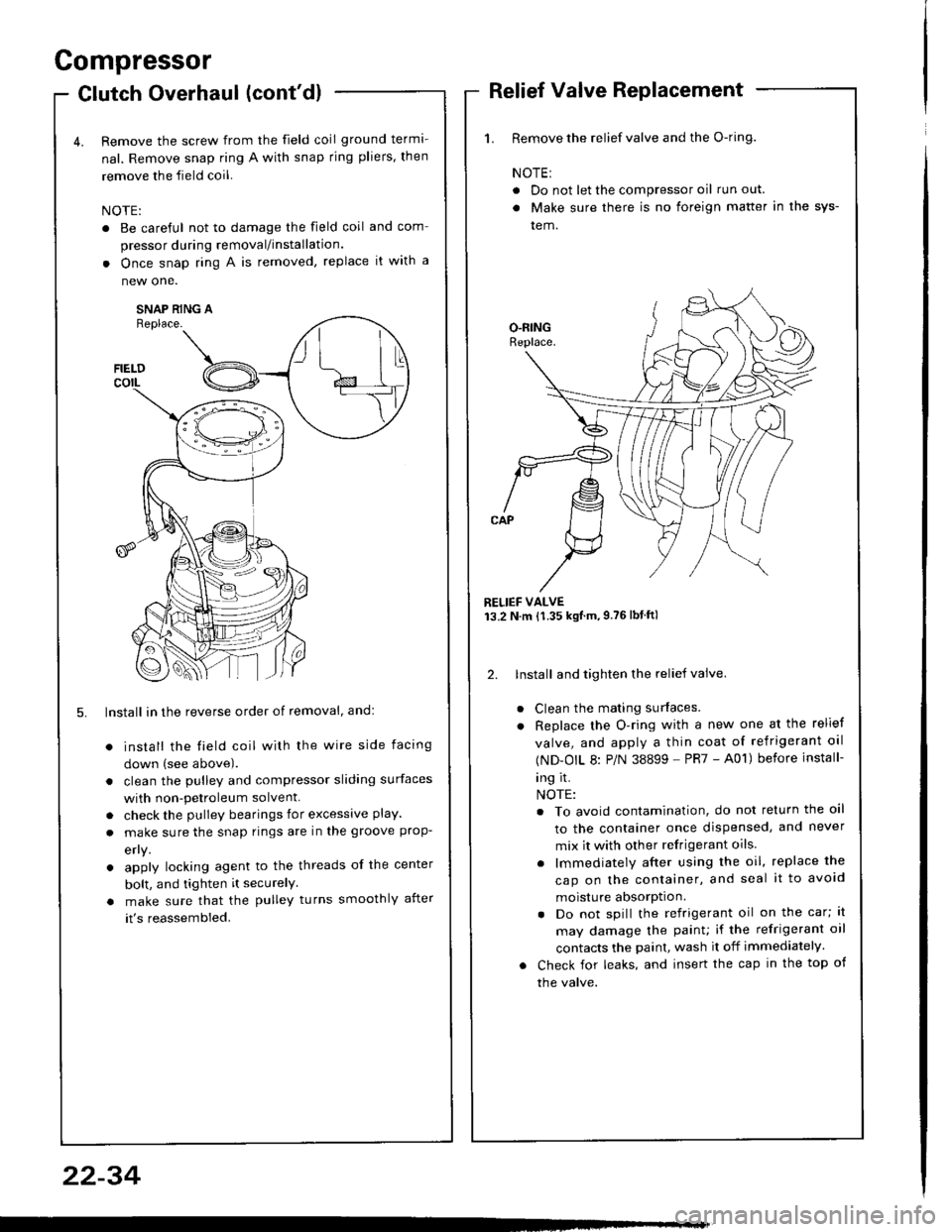
Remove the screw from the field coil ground terma-
nal. Remove snap ring A with snap rjng pliers, then
remove the field coil.
NOTE:
. Be careful not to damage the field coil
pressor during removal/installation.
. Once snap ring A is removed, replace
new one.
SNAP RING AReplace.
FIELDcorL
5. lnstall in the reverse order of removal, and:
install the field coil with the wire side facing
down (see above).
clean the pulley and compressor sliding surfaces
with non-petroleum solvent.
check the pulley bearings for excessive play.
make sure the snap rings are in the groove prop-
efly.
apply locking agent to the threads of the center
bolt, and tighten it securelY
make sure that the pulley turns smoothly after
it's reassembled.
1. Remove the relief valve and the O-ring.
NOTE:
. Do not let the compressor oil run out.
. Make sure there is no foreign matter in the sys-
tem.
RELIEF VALVE13.2 N.m {1.35 kgtm,9.76lbtftl
2. lnstall and tighten the relief valve.
Clean the mating surfaces.
Replace the O-ring with a new one at the relief
valve, and apply a thin coat of refrigerant oal
(ND-OIL 8: P/N 38899 - PR7 - A01) before install-
ing it.
NOTE:
. To avoid contamination, do not return the oil
to the container once dispensed, and never
mix it with other refrigerant oils.
. lmmediately after using the oil, replace the
cap on the container, and seal it to avoid
moisture absorption.
. Do not spill the refrigerant oil on the car; lt
may damage the painu if the refrigerant oil
contacts the paint, wash it off immediately.
Check for leaks, and insert the cap in the top of
the valve.
22-34
Page 1103 of 1413

Condenser
Replacement
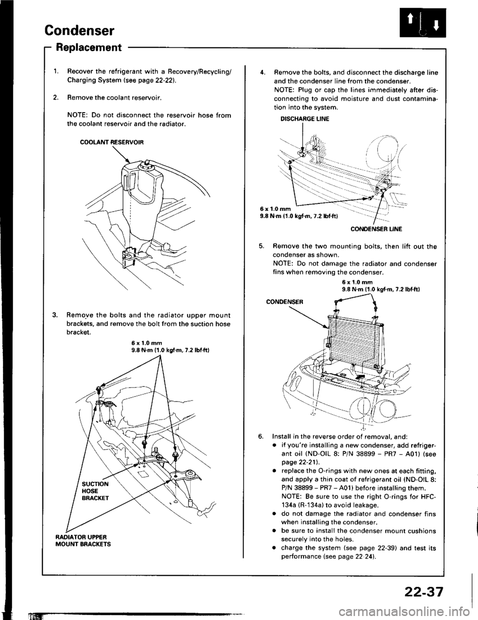
RAOIATOR UPPENMOUNT BRACKETS
Recover the relrigerant with a Becovery/Recycling/
Charging System (see page 22-221.
Remove the coolant reservoir,
NOTE: Do not disconnect the reservoir hose from
the coolant reservoir and the radiator.
COOLANT RESERVOIR
Remo.ve the bolts and the radiator upper mount
brackets, and remove the bolt from thg suction hose
bracket.
9.8 N.m {1.0 kgf.m.7.2 lbtftl
'1Iffi
22-37
6x1.0mm9.8 N.m (1.0 kgl.m,7.2 lbt.ft)
......-.....
CONOENSER LINE
Remove the bolts. and disconnect the discharge line
and the condenser line from the condenser.
NOTE: Plug or cap the lines immediately after dis-
connecting to avoid moisture and dust contamina-
tion into the system.
DISCHARGE LINE
Remove the two mounting bolts, then lift out the
condenser as shown.
NOTE: Do not damage the radiator and condenser
fins when removing the condenser.
6x1.0mm9.8 N.m (1.0 kgf.m, 7.2 lbl.tt)
Install in the reverse order of removal. and:
. if you're installing a new condenser, add refriger-
ant oil (ND-OIL 8: P/N 38899 - PR7 - A01) (see
page 22-21t,.
. replace the O-rings with new ones at each fitting,
and apply a thin coat of refrigerant oil {ND-OIL 8:
P/N 38899 - PR7 - A01) before installing them.
NOTE: Be sure to use the right O-rings for HFC-
134a (R-134a) to avoid leakage.
a do not damage the radiator and condenser fins
when installing the condenser,
. be sure to install the condenser mount cushions
securely into the holes.
. charge the system (see page 22-39) and test its
performance (see page 22 24!�.
Page 1186 of 1413
![HONDA INTEGRA 1994 4.G Workshop Manual Starting
Startel
System
Overhaul
from clutch side.
-s@]
MOLYBDENUMDISULFIDE
CAUTION: Disconnecl th€ battery n€gative cable befole
lomoving the startet.
NOTE: The original radio has a coded theft p HONDA INTEGRA 1994 4.G Workshop Manual Starting
Startel
System
Overhaul
from clutch side.
-s@]
MOLYBDENUMDISULFIDE
CAUTION: Disconnecl th€ battery n€gative cable befole
lomoving the startet.
NOTE: The original radio has a coded theft p](/manual-img/13/6067/w960_6067-1185.png)
Starting
Startel
System
Overhaul
from clutch side.
-s@]
MOLYBDENUMDISULFIDE
CAUTION: Disconnecl th€ battery n€gative cable befole
lomoving the startet.
NOTE: The original radio has a coded theft protection
citcuit. Be sure to get the customer's code number before
- disconnecting the batterY.- removing the No.3 2 (7.5 A) fuse from the under-hood
fuse/relay box.- removing the tadio.
Atter service, reconnect power to the radio and turn at
on. When the word "CODE" is displayed, enter the cus-
tomer's 5-digit code to restore radio operation.
tr./.' BRUSH HOLDERTest, page 23-8'l
ERUSH
COVER
I
6
OVERRUNNING CLUTCH ASSEMBLYInspection, page 23_84
SOLENOIDPLUNGERInspection, page 23-85
BRUSH HOLOER
ARMATURE
STARTERSOLENOIDTest, page 23-78
PINION GEAR IDLER GEAR
Inspection, page 23-11
IDLER GEAR
I
@*
SOLENOID HOUSING
HARNESS BRACKET
STEEL BALL
install steel ball
lnspection and Test,page 23-82
ROLLER BEARINGSand CAGEPrevenl rollers trom being scattered and lost.
MOLYBDENUM DISULFIDE
_R1
MOLYADENUMDISULFIDE
23-80
ENO COVER
ARMATURE
GEAR HOUSING
Page 1211 of 1413
Alternator Overhaul
CAUTION: Do not r€move th€ pulley unl€Es the t.ontbearing needs r6placsm6nt.
To loosen the pulley locknut, use 10 mm and 22 mmwrenches. It necessary, use an impact wrench.
Test, page 23-107SPAC
REAR BEARING
ER RING
rl
@n
CAUTION: Do not get grease
or oil on the slip rings.
HOLDERTOR
ARUSH HOLOER
FRONT BEARING
PULLEY LOCKI{UT1'll N.m 111.3 kgt.m,82 tbf.trl
STATOR/DRIVE ENDHOUStt{G
BBUSHINSULA
)
(@P "
STATOR THROUGHBOLT
VOLTAGE REGULATOR
DIODE IRECTIFIER) ASSEMBLYTest, page 23-106
6
q
%A
re
TERMINAL INSULATORqt
PULLEY LOCKNUT111 N.m (1 1.3 kgt.m, 82 lbf.ft)
PULLEY
10 mm BOX WRENCH
REAR HOUSING
Inspection, page 23-
fu"- "o*n.r" ".,"- BRACKET
23-105
Page 1213 of 1413
Rotor Slip Ring Test
1 . Check thst there is continuity between thg slip rings.
ROTOR SHAFT
Check th8t there is no continuity betw€en the slip
rings and the rotor or rotor shaft.
lf the rotor fails either continuity check, rsplace th€
alternator.
2
3
Stator Test
1. Chock that there is continuity between each pair ofl6ads.
Ch6ck that there is no continuity between each lead
and the coil core.
lf th€ coil fsils either continuity check. replace the
alt6rnator.
cotl coRE
23-107
Page 1376 of 1413

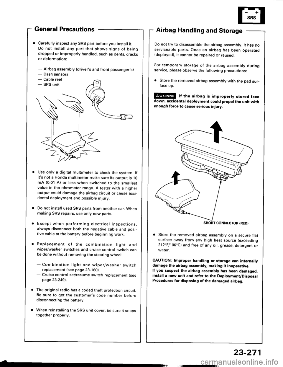
- Dash sensors- Cable reel- SRS unit
General Precautions
Carefully inspect any SRS part before you install it.Do not install any part that shows signs of beingdropped or improperly handled, such as dents, cracksor deformation:
- Airbag assembly {driver's and front passenger's)
Airbag Handling and Storage
Do not try to disassemble the airbag assembly. lt has noserviceable parts. Once an airbag has been operated(deployed), it cannot be repaired or reuseo.
For temporary storage of the airbag assembly duringservice, please observe the following precautions:
. Store the removed airbag assembly with the pad sur-face up.
!@ It the airbag is impropsrty stored facsdown, accidental deployment could propel the unit withenough force to cause setious iniury
Store the removed airbag assembly on a secure flatsufface away from any high heat source (exceeding
212"Fl1OO'Cl and free of any oil. grease, detergent or
CAUTION: lmproper handling or storage can internallydamage the airbag assembly, making it inoperativ€.ll you suspect the airbag assembly has been damagod,install a new unit and rgler to the Deployment/DigposalProcedures lor disposing of the dsmaged airbag.
Use only a digital multimeter to check the system. lfit's not a Honda multimeter make sure its output is 10mA (0.01 A) or less when switched to the smallestvalue in the ohmmeter range. A tester with a higheroutput could damage the airbag circuit or cause accidental deployment and possible injury.
Do not install used SRS parts from another car. Whenmaking SRS repai.s, use only new pans.
Except when performing electrical inspections,always disconnect both the negative cable and posi-
tive cable at the battery before beginning work.
Replacement of the combination light andwiper/washer switches and cruise control switch canbe done without removing the steering wheell
- Combination light and wiper/washer switchreplacement (see page 23-160).- Cruise control sevresume switch replacement {seepage 23-2491 .
The original radio has a coded theft protection circuit.Be sure to get the customer's code number beforedisconnecting the battery.
When reinstalling the SRS unit cover, be sure it snapstogether properly.
SHORT CONNECTON {REDI
23-271