1994 HONDA INTEGRA Rings
[x] Cancel search: RingsPage 660 of 1413

Reassembly
NOTE:
. Clean the disassembled parts with a solvent and dry them with compressed air. Do not dip the rubber parts in a sol-
vent.
. Always replace the O-rings and rubber seals with new ones before assembly.
. Apply power steering fluid or steering grease {HONDA P/N: 08733 - 8070E) to the parts indicated in the assembly pro-
cedures.
. Do not allow dust, dirt. or other foreign materials to enter the power steering system.
. Use the appropriate specialtools where necessary.
FLANGC BOLT20 N.m 12.0 kg{.m, lil lbt'ftl
CYLINDER PIPE A26 N'm (2.7 kgf.m, 20 lbf.ftl
VALVE I{OUSING
BOLI..ER BEARINGReplace.
VALVE SEAL RINGReplace.+-cncl|P
RACK GUIDE SCREW
S1IEVE SEAI RINGSReolace.
SITEVE
BACKUP RIM}
VALVE SEAL RINGRaplacs.
O.RINGReplac€.LOCKNUT
CYLINDER HOUSING
O-RINGBACKUP RING Replace.
\
PINION SHAFT
SHIMS
O-RINGReplace.
CYUNDER END SEALReolace.GEAR HOUSING
CYLINDER END SEALReplaco.O.RINGReplace.
I
x nd#$Y
IPISTON SEAL RINGReplace.
STEERING RACK
(cont'd)
17-53
Page 661 of 1413

Steering Gearbox
Reassembly lcont'd)
Vllvc Body Rea3sombly
1. Apply vinyl tape to the stepped portion of the pin-
ion shaft, and coat the surface of the vinyl tape with
the power steering tluid,
2. Install the backup ring with its tapered side as
shown below.
3. Coat the inside surface of the new valve oil seal
with power steering fluid.
4. Slide the valve oil seal over the pinion shaft. being
careful not to damage the sealing lip.
CAUTION: ln3tall the valve oil ssal with hs groovad
3ide tacing opposits the besring.
Vinyl trpolst.ppcd ponion,Tapered position.
Groove side.
VALVE OIL SEAL
Fit the new O-ring in the groove of the pinion shaft.
Then slide the new valve seal ring over the shaft
and groove in on the pinion shaft.
Remove the vinyl tape from the pinion shaft.
NOTE: Do not over - expand the valve saal ring.
S€aling
E
lip
PINION SHAFT
VALVE SEAL RING
17-54
7. Apply power steering fluid to the surface of the
valve seal ring that was installed on the pinion
shaft.
8. Apply power steering fluid to the inside of the spe-
cial tool. Set the larger diameter end of the special
tool over the valve seal ring.
9. Move the special tool up and down several times to
make the valve seal ring Jit in the pinion shaft.
10. Remove the special tool.
.11. Turn the special tool over and setthe smallerdiam-
eter end of the special tool over the valve seal ring.
Move the sDecial tool uD and down severai times to
make the valve seal ring snugly fit in the pinion
shaft.
VALVE SEAL RING
(H(ffi
Use the wider diameterend ot the specialtool first to makethe valve seal ringfit in the pinionshaft.
Make the valve seal ringsnugly fit in the.pinionshaft using the other end(smaller diameter end) ofthe specialtool.
Page 662 of 1413

Apply power steering fluid to the surface of the spe-
cial tool. Set the new seal rings over the special tool
from the smaller diameter end of the tool, and
expand the seal rings. Do two rings at a time from
each end of the sleeve,
NOTE:
. Do not over-expand the seal ring. Install the resin
seal rings with care so as not to damage them.
After installation, be sure to contract the seal
rings using the specialtool {sizing tool}.
. There are two types of sleeve seal rings: black
and brown. Do not mix the different types of
sleeve seal rings as they are not compatible.
Set the special tool in the grooves in the sleeve. and
set each ring in each groove securely.
NOTE: After installation, compress the seal rings
with your fingers temporarily.
BALL JOINT BOOT CLIP GUIDEo?MAG - SL001d)
14. Apply power steering fluid to the seal rings on the
sleeve and to the entire inside surface of the special
tool.
15. Insert the sleeve into the specialtool slowly.
16. Move the sl€eve each direction several times to
make the seal rings snugly fit in the sleeve.
NOTE: Be sure that the seal rings are not turned up.
SLEEVE SEAL RINGSIZING TOOL
13.
07974 - 5450200
Cutout,
't7.Apply power steering fluid to the surface ol the pin-
ion shaft, then assemble the sleeve over the pinion
shaft, aligning the locating pin on the inside of the
sleeve with the cutout in the shaft,
NOTE: Be careful not to damage the valve seal ring
when inserting the sleeve.
Install the circlip securely in the pinion shaft groove.
NOTE: Install rh€ circlip with its tapered side facing
OUI.
19. Apply power steering fluid to the seal ring lip of the
valve oil seal. Then install the seal in the valve
housing using a hydraulic press and special tools as
shown.
18.
ATTACHMENT,32x35mm077{6 - 0010100
{cont'd)
VALVE OIL SEAL
17-55
ir
Page 663 of 1413

Steering Gearbox
Reassembly (cont'd)
SI,-EEVE SEAL RINGSBe sure that thesear ings are notturned up, theninstall.
Press the new roller bearing into the valve housing
using a hydraulic press and special tool as shown.
NOTE: Place ths roller bearing on the valve hous-
ing with its letter stamped facing up towards the
valve side.
Pr.33,
I
PINION
E
20.
ATTACHMENT,32x35mm077/aO - (x)1010O
ROLLER BEARINGLetter stamped face
21.Apply vinyl tape to the pinion shaft, then coat thevinyl tape with power steering fluid.
Insert the pinion shaft into the valve housing.
CAUTION: Be carotul not to damage tho valvs soalrings.
23. Remove the vinyltape from the pinion shaft.
Soaling lip frc..
VALVE OIL SEAL
VALVC HOUSING
17-56
24. Press the pinion shaft/sleeve using a hydraulic
Dress as shown.
CAUTION: Before irserting the pinion 3haft, bosuro that the backup ring is csntored with the pin.
ion shaft bearing,
BACKUP BING
Page 664 of 1413

25.
26.
Coat the piston seal ring guide with power steering
fluid, and slide it onto the rack, big end first.
Position the new O-ring and new piston seal ring on
the special tool, then slide them down towards big
end of the tool.
NOTE:
. Do not over expand resin seal rings. Install the
resin seal ring with care so as not to damage
them. After installation, be sure to contract the
seal ring using the special tool (sizing tool).
. Replace piston's O-ring and seal ring as a set.
Pull the O-ring off into the piston groove, then pull
the piston seal ring off into the piston groove on top
of the O-ring.
PISTON SEAL RING
GUIDE07GAG - SD,OI00
28.
30.
O.RING
PISTON SEAL RING
Coat the piston seal ring and inside of the special
toolwith power steering fluid.
Carefully slide the tool onto the rack and over the
piston seal ring.
Move the special tool back and forth several times
to make the piston seal ring fit snugly in the piston.
PISTON
E
PISTON
31.
32.
Coat the sliding surface of the special tool and new
cylinder end seal with power steering fluid.
Place the seal on the special tool with its grooved
side facing opposite the special tool.
Grooved side.
CYLINDER ENDSEAL SLIDER0797a - 6890801
Apply a thin coat of grease to the inside of the spe-
cial tool, and install it on the steering rack.
CAUTION: Make sure the rack teeth do not tace
the slot in the special tool.
SEAL SLIDER0t974 - 6890801(cont'd)
CYLINDER END SEAL
CYLINOER END SEAL
17-57
Page 1074 of 1413

Description
Outline
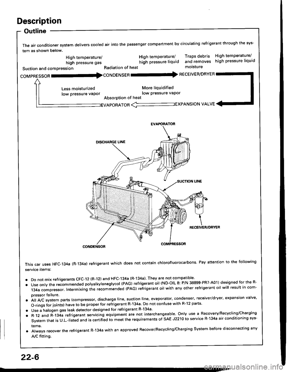
The air conditioner system delivers cooled air into the passenger compartment by circulating refrigerant through the sys-
tem as shown below.
CONDENSOR
This car uses HFC-134a {R-134a) refrigerant which does not contain chlorofluorocarbons Pay attention to the following
service items:
. Do not mix refrigerants CFC-I2 (R-l21 and HFC-134a (R-134a) They are not compatible'
. Use onty the recommended potyatkytenegtycol {PAG) refrigerant oil (ND-OIL 8: P/N 38899-PR7-A01) designed for the R-
134a compressor. Intermixing the recommended (PAG) refrigerant oil with any other refrigerant oil will result in com-
pressor tailure.
.A||lvcsystemparts(compressor.dischargeIine,suotionIine,evaporator,condenser.receiver/dryer,expansionva|ve.
o-ringsforioints}havetobeproperforre'rigerantR-l34a.DonotconfusewithR.l2parts.
. Use a halogen gas leak detector designed for refrigerant R-134a'
. R-.12 and C-l34a refrigerant servicing equipment are not interchangeable. Only use a Recovery/Recyclins/Charging
System that is U.L.-listed and is certifLd to meet the requirements of sAE J2210 to service R-134a air conditioning sys-
rems.
. Always recover the refrigerant R-134a with an approved Recover/Recycling/Charging System before disconnecting any
A,/C fitting.
coMpRESsoR -coNDENSER - RECEIVER/DRYER
High temperature/
high pressure gas
Suction and comPression
Less moisturized
low pressure vaPor
High temperature/ Traps debris High temperature/
hilh pressure liquid and removes high pressure liquid
Radiation of heat molsture
More liquidified
low Pressure vaPor
Absorption of heat
EVAPORATOR <-'----------.- EXPANSION VALVE
EVAFORATOR
22-6
Page 1094 of 1413

Evaporator
Replacement
CATION:
. All SRS eloctrical wiring harnesses are coverod with
yollow in3ulation.
. B€tore disconnocting 8ny part of tho SRS wire har-
nsss, conngqt th€ 3hort connestor{sl.
. Roplaca ths entire aftected SRS harness a$embly if
it has an op€n circuit or damaged wiring.
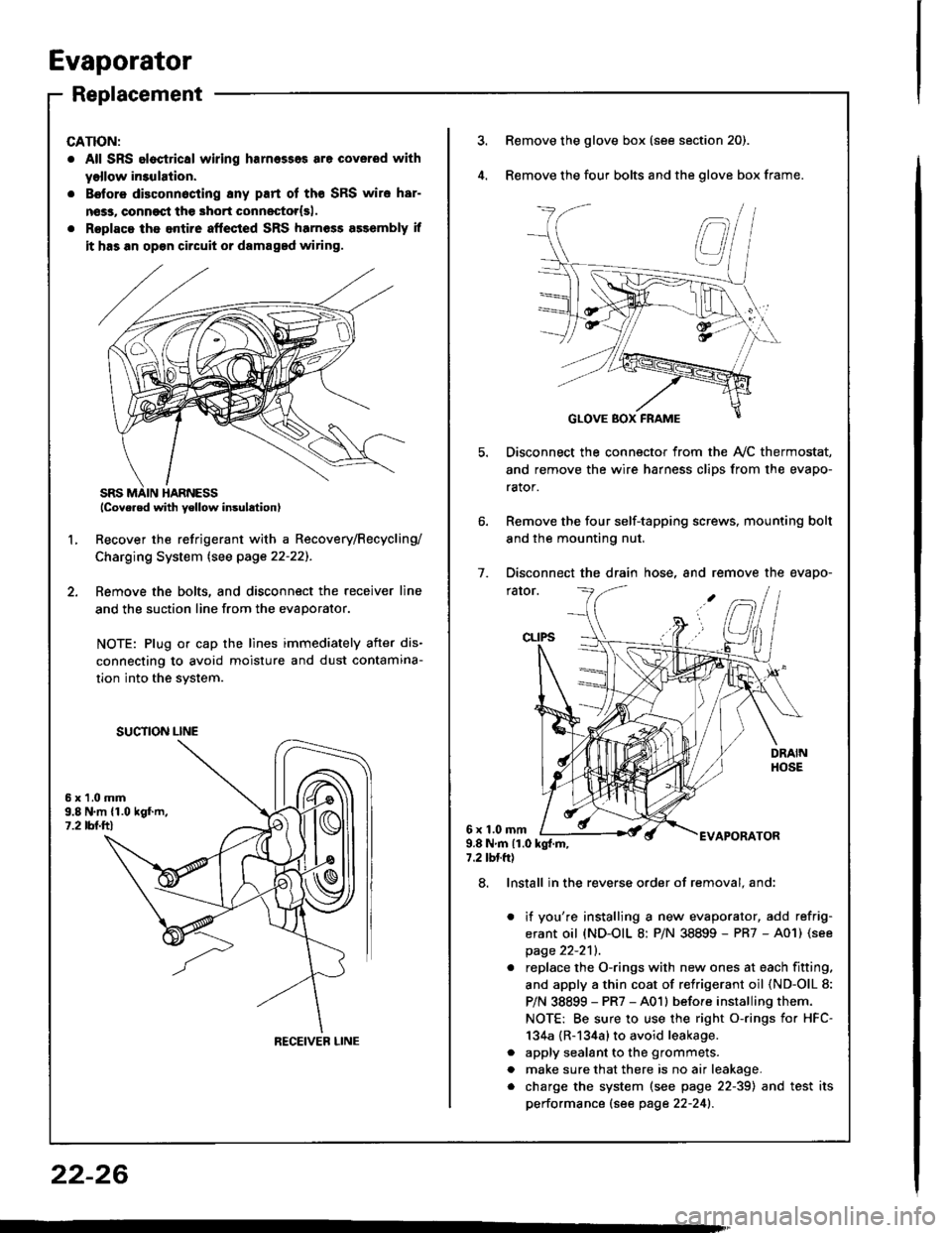
lcove.ed with yellow insulation)
Recover the refrigerant with a Recovery/Recycling/
Charging System lsee page 22-22]-.
Femove the bolts, and disconnect the receiver line
and the suction line from the evaporator.
NOTE: Plug or cap the lines immediately after dis-
connecting to avoid moisture and dust contamina-
tion into the svstem.
2.
L
6x1.0mm9.8 N.m {1.019f.m,1.2 tbl.ttl
SUCTION LINE
RECEIVEB LINE
3.Remove the glove box (see section 20).
Remove the four bolts and the glove box frame.
Disconnect the connector from the Ay'C thermostat,
and remove the wire harness clips from the evapo-
rator.
Remove the four self-tapping screws, mounting bolt
and the mounting nut.
Disconnect the drain hose, and remove the evapo-
rator.
1.
6x1.0mmAPORATOR9.8Nm{1.0kg{.m,7.2 tbtft)
a
a
8. Install in the reverse order of removal. and:
it you're installing a new evaporator, add refrig-
erant oil (ND-OIL 8: P/N 38899 - PR7 - A01) (see
page 22-2'll.
replace the O-rings with new ones at each fitting.
and apply a thin coat of refrigerant oil (ND-OlL 8:
P/N 38899 - PR7 - A01l before installing them.
NOTE: Be sure to use the right o-rings for HFC-
134a {R-134a} to avoid leakage.
apply sealant to the grommets.
make sure that there is no air leakage.
charge the system (see page 22-39) and test its
performance (see page 22-241.
22-26
Page 1095 of 1413

Overhaul
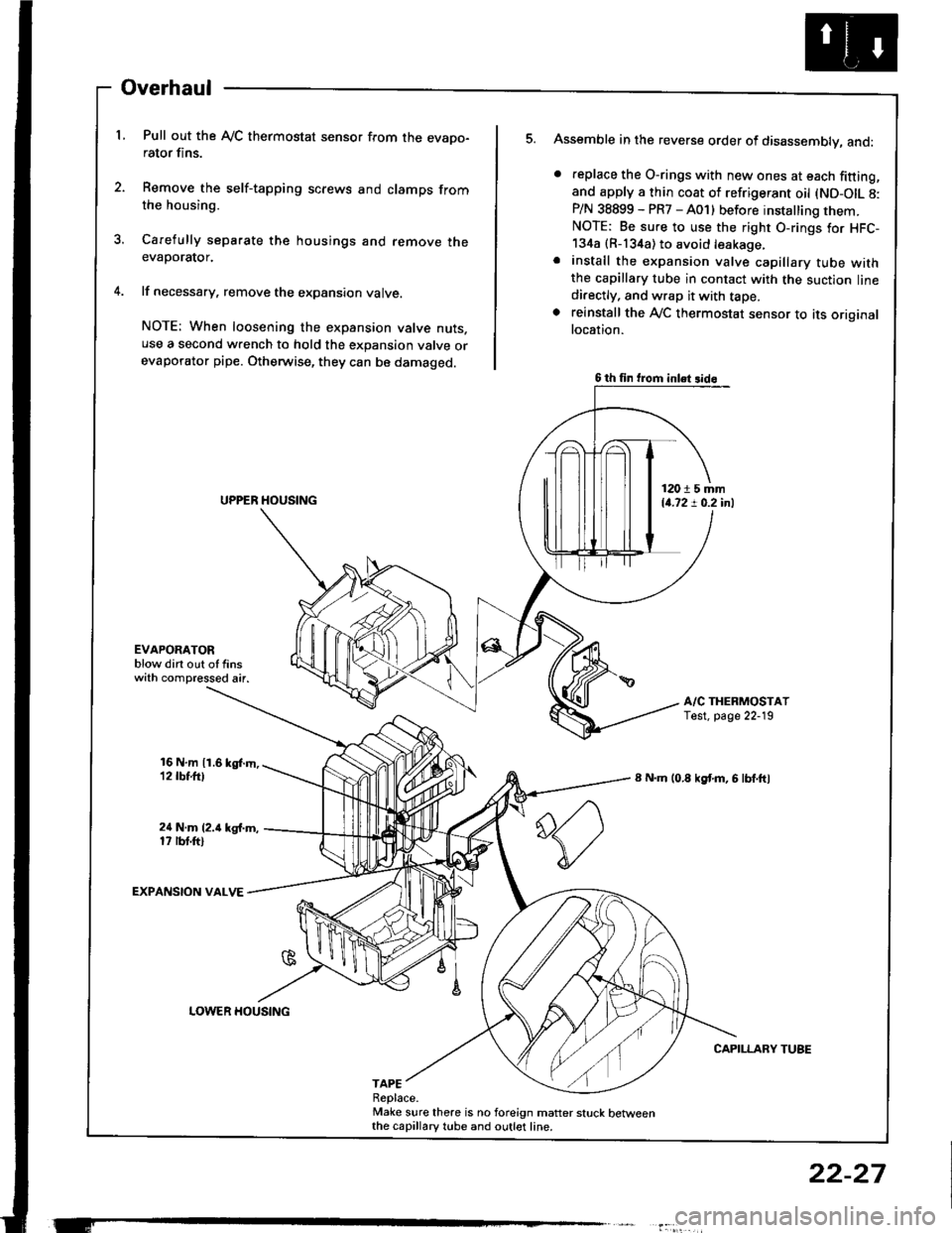
L Pull out the Ay'C thermostat sensor from the evapo-rator fins.
2. Remove the self-tapping screws and clamps fromthe housing.
3. Carefully separate the housings and remove theevaporator.
4. lf necessary, remove the expansion valve.
NOTE: When loosening the expansion valve nuts.use a second wrench to hold the expansion valve orevaporator pipe. Otherwise, they can be damaged.
Assemble in the reverse order of disassembly, and:
. feplace the O-rings with new ones at each fitting,and apply a thin coat of refrigerant oil (ND-OIL 8:P/N 38899 - PR7 - A01) before installing them.NOTE: Be sure to use the right O-rings for HFC-134a {R-134a) to avoid leakage.. install the expansion valve capillary tube withthe capillary tube in contact with the suction linedi.ectly, and wrap it with tape.. reinstall the Ay'C thermostat sensor to its originallocation.
A/C THERMOSTATTest. page 22-19
8 N.m (0.8 kgf'm, 6 lbf.ftl
CAPILLARY TUBE
5.
EVAPOAATORblow dirt out of finswith compressed air.
16 N,m 11.6 kgl.m,12 tbt.ttl
24 N.m (2.i1 kg{.m,17 rbt.ftl
EXPANSION VALVE
TAPEReplace.Make sure there is no foreign matter stuck betweenthe capillary tube and outlet line.
6 th fin trom inlet 3id6
12015 mm14.72 ! 0.2 inl
LOWER HOUSING
22-27