Page 1001 of 1413

Dashboard
Component Removal/lnstallation (cont'dl
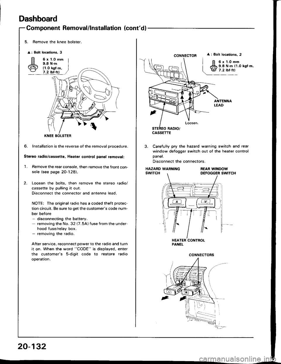
5. Remove the knee bolster.
: Bolt locations, 3
fi 6rt.omm
6 i;i'i#.,7.2 tbr.ftl
?
KNEE
6. Installation is the reverse of the removal Drocedure.
Stol€o radio/cassette, Heater control panal removal:
1 . Remove the rear console, then remove the front con-
sole (see page 20-128).
Loosen the bolts, then remove the stereo radio/
cassette by pulling it out.
Disconnect the connector and antenna lead.
NOTE: The original radio has a coded theft protec-
tion circuit, Be sure to get the customer's code num-
ber belore- disconnecting the battery.
removing the No. 32 17.5A) fuse from the under-
hood fuse/relay box.- removing the radio.
After service, reconnect power to the radio and turn
i1 on. When the word "CODE" is displayed. enter
the customer's 5-digit code to restore radio
operation.
20-132
CONNECTOR
CASSETTE
i Bolt locations. 2
6 x 1.0 mm9.8 N.m {1.0 kgl.m,
3, Carefully pry the hazard warning switch and rear
window defogger switch out of the heater control
Daner.
Disconnect the connectors.
HAZARD WARNINGswtTcHREAR WINOOWDEFOGGER SWITCH
Page 1003 of 1413
Dashboard
4.
20-134
Component Removal/lnstallation (cont'd
Side air vent .emoval:
Drivsi's
1. Remove the dashboard lower cover (see page
20-1 31 ).
2. Caretully pry the moonroof switch out of the side
air vent, then disconnect the connector.
MOONROOFswrTcH
CONI{ECTOR
SIDE AIRVENT
3, Remove the screw, then remove the side air vent.
< : Clip, hook locatlont
A< : Clip, 1
BV : Hook, 3
lnstallation is the reverse of the removal procedure.
NOTE: Make sure the connector is connected
properly.
> : Sc.6w location,
I
o@)
SIDE AIRVENT
Front passsng€r'�s
Careiully pry the side air vent at the lower edge, then
pull it out.
A : Clip, hook locationg
AA : Clip, 1BV : Hook, 2
Hi
1.'' 11 ,/
SIDE AIRVENT
PROTECTIVETAPE
Sido detoggor t m romoval:
Carefully pry the side detogger trim at the rear edge, then
remove rt.
A : Cllp, hook location!
AA : Clip,lB A: Hook, 1
PROTECTIVE
Page 1005 of 1413

Dashboard
Replacement Precautions
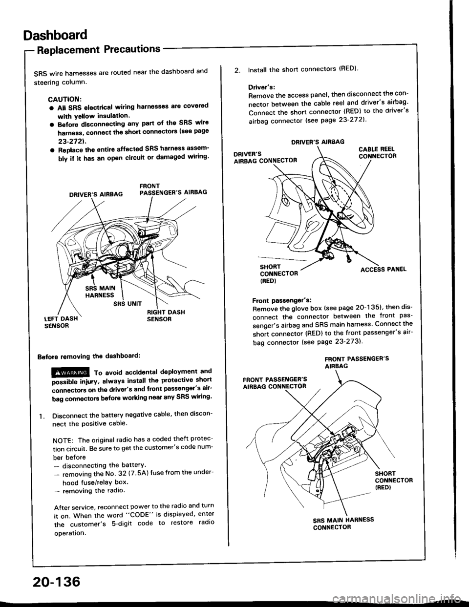
SRS wife harnesses are routed near the dashboard and
steering column.
CAUTION:
a Alt SRS olectrical wiling harness€s ale covorad
with Yollow insulation.
a Botore disconnecting any part ot the SRS wiro
harness, connect ths short connscto6 (see page
23-2721.
a Roplac6 ih€ entiro aflectod SRS halnoss assem-
bly il it has an opon cilcuit or damagod wiling'
LEFT DASHSENSOR
Bstora lomoving the dashboaid:
!@@ To avord accioenlal dsployment and
""iUU inir.v, always install the plotoctive short
;onnectors on the driver's and tlont pass€ngel's air-
bag connectors bolors working near any SRS wiring'
1. Disconnect the battery negative cable, then discon-
necl the positive cable.
NOTE: The original radio has a coded theft protec
tion circuit. Be sure to get the customer's code num-
ber before- disconnecting the battery.
- removing the No 32 (7.5A) Iuse from the under-
hood fuse/relaY box'- removing the radio.
After service, reconnect power to the radio and turn
it on. When the word "CODE" is displayed, enter
the customer's 5 digit code to restore radlo
ooeration.
DRIVER'S AIREAG
SRS UNIT
20-136
DRIVER'S AIRBAG
2.lnstall the short connectors (RED)
Ddvar's:
Remove the access panel, then disconnect the con-
nector between the cable reel and driver's airbag'
Connect the short connector (RED) to the driver's
airbag connector lsee page 23-27 2l'
DRIVER'SAIRBAG CONNECTOB
CABLE REELCONNECTOR
SHORTCONNECTOR(RED)
Front passongor's:
Remove the glove box {see page 20-135}, then dis-
connect the connector between the tront pas'
senger's airbag and SRS main harness Connect the
short connector (RED) to the front passenger's air-
bag connector (see Page 23-273).
FROf{T PASSENGER'SAIRBAG
ACCESS PAI{EL
FRONT PASSET{GER'SAIRBAG CONNECTON
SHORTCONNECTOR(REDI
SBS MAIN HARNESS
CONNECTOR
Page 1006 of 1413

Replacement
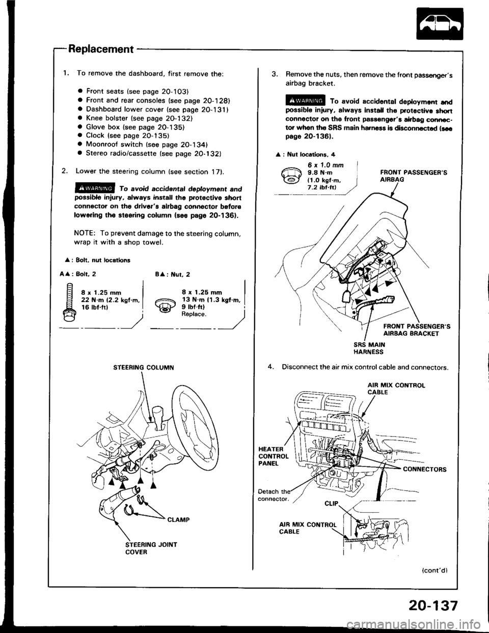
To remove the dashboard, first remove the:
a Front seats (see page 2O-103)
a Front and rear consoles (see page 20-128)a Dashboard lower cover (see page 2O-131)a Knee bolster (see page 2O-132)a Glove box lsee page 2O-135). Clock (see page 20-135)
a Moonroot switch (see page 20-1341a Stereo radio/cassette {see page 20-132)
Lower the steering column (see section 17).
@@ ro avoid accidentat dedoyment andpossiblo in ury, always install the prot€ctive short
connector on tho drivsr's airbag connector bgtor€
lowering tho stooring column (so€ page 20-1361.
NOTE: To prevent damage to the steering column,
wrap it with a shoD towel.
: 8olt, nul locations
A
: Bolt, 28 : ut, 2
8 x 1.25 mm22 N-m 12.2 ksl.m,16 lbt.frl
8 x 1.25 mm
gill$"'l
STEERING COLUMN
3. Remove the nuts, then remove the front passsnger,s
airbag bracket,
@ To avoid accidantar daploym.nr ",'dpossibls iniury, always install th€ protoctiv. 3hqtconnoctor on tho ,ront passongor'a airbag conncc-tor whon tha SRS main ha.na$ is disconncctod llcrpago 20-136).
: Nut locatlons, 4
FRONT PASSENGER'S
FRONT PASSENGER'SAIRBAG BRACKET
4.
SRS MAINHARNESS
Disconnect the air mix controlcable and connectors.
AIR MIX CONTROLCAELE
CONNECTORS
(cont'dl
20-137
Page 1010 of 1413
Rear Bumper Replacement
NOTE:
a An assjstant is helpful when femoving the rear bum-per and rear bumper beam.
a Take care not to scratch the rear bumper.
Hatchback
1. Remove the screw from each side.
REAR BUMPER
Open the hatch, then remove the rear trim panel (see
page 20-921-
Remove the nuts, and disconnect the license plate
light connector and grommet.
Scrow I
A
A\
:
J.
> : Nut locotions, 4
/ 6x1.Omm I
Q) i;L'i$-. l
_':'y:) ,/BIGHT SIDETRIM PANEL
To remove the nuts, remove the rearportion of the side trim panel oneach slde {see page 20-921.
LEFT S|DE L|CENSE PLATE LtcHT
4. Remove the bolts, then remove the rear bumper.
: Bolt locations, 2
5. lf necessary, remove the bumper upper beam from
the rear bumper.
: Screw locotions
A : Scr€w, 4 B <: Sc.ow, 4 V: Clip locations, I
REAR BUMPER
--E- I
.--r-Fl^ |--lEr-
_\"., J
^i
@sl
_'/
LICENSE PI-ATELIGHT HARNESS
(cont'd)
REAR BUMPER
20-141
Page 1011 of 1413
Bumpers
Rear Bumper Replacement (cont'dl
6. Remove the absorber, bumper beam gusset and rear
bumper beam.
y: Bolt localions, 4
12 x 1.25 mm I
64Nm{65kgfm,I* "r:,
)ACCESS CAP
LlF/d,rft
REAR EUMPERBEAMEUMPER BEAMGUSSET
lnstallation is the reverse of the removal prcedure.
NOTE: Make sure the license plate light connector
is connected, and the grommet is installed properly,
20-142
Sadan
1. Remove the screw from each side
: Sciow locations, 2
REAR BUMPER
2. ODen the trunk lid, then remove the rear trim panel
(see page 20-97).
3. Disconnect the license plate light connector and
grommet from the rear trunk atea. Remove the clips
and bolts, then remove the rear bumper'
v: Cllp loc.tions, 5 : 8ok locations, 2
€l
#.,1
9.8 N.m il1.O kgl m, I7.2 rbr.ft) J
6 x 1.0 mm I
GBOMMET
Page 1012 of 1413
4. lf necessary, remove the license plate light harness,bracket and lens from the rear bumper (see page20-1411.
5. Remove the absorb€r, bumper beam gusset and fearbumper beam.
V i Bolt locatlons, 4
REAR BUMPERBEAM
BUMPER BEAMGUSSET
12 x 1.25 mm64 .m (6.5 kgf47 tbt.ftl
I.m, j
)
6. Installation is the .everse of the removal procedure.
NOTE:
a Make sure the license plate light connector is con-
nected, and the grommet is installed properly.
a Make sure the rear bumper engages the side clips
securelv.
REAR BUMPER
20-143
Page 1013 of 1413
Hood
Replacement
NOTE:
a An assistant is helplul when removing the hood.
a Take care not to damage the hood and body.
a When removing the clips, use a clip remover.
a Open the hood.
1. It necessary, remove the hood edge protector.
: Clip loc.tions, 16
NOTE: It necessary, remove the hood hinge.
V : Boh locationa, 4
I3;;,iH"-,,., I
j .rtor"t
- )
HOOD EDGEPROTECTOR
\HOOD
2. Remove the bolts. then remove the hood.
: Bolt localions, 4
lnstallStion is the reverse of the removal procedure.
NOTE:
a lf necessary, replace any damaged clips.
a Make su.e the hood locks securely.
a Make sure the hood opens properly.
a Adjust the hood alignment (see page 20-1451.
6x1.0mm9.8 N'm{l.O kgl m,7.2 lbl.fr)
HOOD HINGE
n
r)
HOOD
20-144