Page 1047 of 1413
Does the blower motor run atprogressively higher speeds?Raplaca tho hollar fan rwitch.
Ropair opon or cau36 ol oxcoalivtrosbtanco in tho appaopaiatowire(3| b6twoon thg hostct lanswitch and tho blower todstor.
Turn the ignition switch OFF.
Remove the heater control panel(see page 21-25).
Check each wire for continuity be-tween the heater tan switch 6Pconnector and body ground.. BLU wire. BLUMHT wire. BLU/YEL wke. BLU/BLK wire
Raplaca tha haater lan awltch.
Bopair shon in the wir6{s} b€-lwo€n lho heatot lan switch rndth6 blowor ro3bto?.
From page 21-9
From page 21-9
View trom whe side
ilil
!\i
-l
I
View from wire side
BLU/U,HT
Troubleshooting
Blower Motor Speed (cont'd)
21-10
--
Page 1048 of 1413
Blower Motor
View from wire side
View from wire side
Blowor motor doos noi iun at all.
check the No. 37 (4o A) fuse intho under-hood fuse/relay box.
At th€ blower motor 2P connec-tor, connect the BLU/8LK wirc ter-minal to body ground wath ajumpe. wire.
Turn the ignition switch ON (ll).
Does the blower motor run?
Disconnect the blower motor 2Pconnector, and measure the vol-tago between the ELU/wHT wireterminal {+} and body ground
{-}.
Turn the ignition switch OFF.
Remove the blower motor relavfrom the under-hood fuse/relavbox and test it {see page 21-3O}.
Roplaco tho blowor motor rolay.
Measure the voltage betwgen theNo. 1 terminal (+) and bodyground (- ).
To page 21-12
To page 2l-13
"uf"'\'
,)
(cont'dl
21-11
Page 1049 of 1413
From page 21-11
Turn the ignition switch OFF.
Remove the heater control pan6l(see page 21-25).
Turn the ignition switch ON (lll.
Measure the voltage b€twsen the8LU/BLK wire terminal l+) andbody ground {- ).
Rgp.lr op.n In lh. BLU/BLK wh.batwoen lh! blowar motor lndtho hcolar f.n .wltch.ls there battory voltage?
Turn the ignition switch OFF.
Check tor continuity in lhe BLKwire between the heater lanswitch and body ground.
Ch.ck tor an opan in lhr Bl-K wirobdtwaan tho hortar tln lwftch.nd body ground. lf tho wlra l.OK, ch.ck for poor ground .tG201 .nd /rO1.
Roplaco tho hsator tan lwitch.
Troubleshooting
Blower Motor (cont'dl
View trom wire side
BLU/BLK{ + }
21-12
Page 1050 of 1413
From page 21-11
Tu.n the ignition switch ON (ll).
Measure tho voltage botwoon thoNo. 4 torminal (+) 6nd bodvground (- l.
Ropair opan in tho BLK/YEL wir.batworn lha undor-hood fuaa/ra-hy box snd tho undor-dr.htur./rolay box.
ls there battery voltage?
Turn the ignirion switch OFF.
Check for continuity between theNo. 2 torminal and body ground.
Ch.d( to. !n oF|rn in th6 BLK wirobatwagn lho undar-hood luro/ra-lry box lnd body ground. ll th.wlre it OK. chock tor poo. groundat G2Ol lnd G/lol.
Rop.ir opon in th. BLU/WHT wlr.betweon tho undsr-hood lura/l.-lay box and tho blowor motoi.
Page 1051 of 1413
Troubleshooting
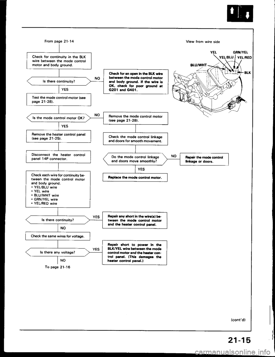
Mode Control Motor
21-14
Modo control motor dooa not nm,
or ono oa moto modo arc In_
oporgtivo.
Disconnect th6 mode control mo_
tor 8P connector.
Turn the ignition switch ON (ll).
Measuroth€ voltage b€tween tho
BLK/YEL wire terminal (+) and
bodv ground (- ).
R.p.lr op.n In lho BLrrYEL wl..
bctw.rn lha undard!.h fuaa/ru-
l.y box .nd ih. mod! corttol
motor.
Turn the ignition switch OFF.
To page 21-1 5
Page 1052 of 1413

From page 21-14
NO
To psg6 2'l - 16
Check for continuity in the BLKwire betweon the mode controlmotor and body ground.
Chock lor an op6n In tho BLK wtbotwo€n tho modo control mototlnd body ground. It thr wlro i!OK, chock for poo. grouhd otG2O1 8nd G/tOl.
Test the modo control motor (seepage 21-281.
Romovo the mode control motor(soo pag6 21-281.ls the mode control motor OKI
Remove the heater control oanel{soe page 21-25).Ch€ck the modo control linkagoand doo.s tor smooth movoment.
Disconnect the heater controlDanel 14P connector.Do tho mode control linkageand doorc movs smoothlv?Ropair th6 mod6 controllinkago or doors.
Ch€ck each wire for continuity bo-twoon the mod6 control motorand body ground.. YEL/BLU wire. Y€L wire. 8LU,^/VHT wire. GRNI/EL wire. YEL/RED wire
Raplace thc modo control moto..
Roprir any .hort in th. wlrol!) b.-tworn tha moda control anototand tha holtar control pan6l.
Check the same wires lor vohage.
Roplir rho.t to powar In tha8LK^'EL wiro b.two.h lh. modoconlrol hotor rnd tha haat* con-trol p!rr.|. (Thi! damrg.. thahello. control p!nel.)
ls the.6 any voltage?
View lrom wi.e side
GRl{/YEL
lconl'dl
21-15
Page 1053 of 1413
View from wire side yELFrom page 21-'l 5
Check each wire for conlinuity be-tween the mode contiol motorand the heater control panel.. YEL/BLU wire. YEL wire. BLU/WHT wire. GRN/YEL wire. YEL/RED wire
R.psir any opon in fro wir6{.1 bo-twocn tho mod€ control motolsnd tho holtar contiol prnal.
Rsploco tho hoator conlrcl panol.
Troubleshooting
Mode Control Motor (cont'd)
21-16
Page 1054 of 1413
Recirculation Control Motor
ffi
Rocirculation control doo. dooanot chsng€ botwoon FRESH 6ndRECIRCULATE.
Disconnect the rgcirculation con-trol motor 4P connector.
Turn the ignilion switch ON l).
Measure the voltage between theBLK^/EL wire rerminal {+) andbody ground (- ).
Reprir op.n In th. BIK/YEL wir.botwoon thr und.r+rh fu!./r.-by box 6nd lha radrculdion co.r-trol motoi.
ls there battery voltage?
Turn the ignition switch OFF.
To page 21-18
{cont'd)
21-r 7