Page 1078 of 1413
Troubleshooting
Condenser Fan
BLU/YEL
View lrom wire side
Remove the condenser fan relay
and test it (see page 22-19).
Replaco the condan3ar frn rclay.
Measure the voltag€ betwe€n the
WHT wire terminal (+) and bodyground (-).
Replir opcn in tho WHT wiro bo-
twoen tha undor-hood fura/Jolay
box rnd tha condonr.rlan rclay.
Connoct the WHT and BLU/BLK
wire terminals with a jumPer
Does the condenser fan run?
Check for continuity in the BLU/
BLK wire between the condenser
Ian relay and the condenser fan
Reprir op€n in th. BLU/BLK wiro
batwcen the condenrai lan rolay
and the condcntor ftn
Check for continuity in the BLK
wire between the condenser fan
and body ground.
Check fot.n op.n in tho BLK
wire botween the condental trn
and bodv g.ound. It the wiro i3
OK, chock lor Poo. ground rt
G151.
Raplaco the condon36r fan motor.
BLK/WHT l+l
10 page 22-11
View from wire side
BLU/BLK
22-10
Page 1079 of 1413
From page 22-10
Disconnect the iumper wire andturn the ignition switch ON (ll).
Measure the voltage between theBLK/WHT wire terminal (+) andbody ground (-).
Reptir open in tha BLK/WHT o.BLK/YEL wire betwoon tho con-den3o. f.n rel.y and tho unde.-dash tus6/rel.y box.
Remove the iay'C diode from theAy'C diode 3P connector.
ls the A,/C diode OK?
Reprir op6n in th. BLU/YEL wirebetwocn tho conden3er tsn reltv.nd tho A/C diod€.
22-11
Page 1082 of 1413
Troubleshooting
Gompressor
R6move the comPressor clutch
refay and test it (see Page 22-19l..
Measuro the voltage bgtlveen th€
WHT wire terminal {+) and body
ground {-}.
Rap.ir op.n in ih. WHT wit.
batwaan tha undar-hood fuaa/
ralay box and thg comptaalol
clutch r.l.y.
Connect tho WHT and 8€D wire
terminals with a jumPer wire.
Disconnect the comPressor
clutch 1P connsctor.
Check for continuity in the RED
wiro botween the comPressorclutch relay and the comPressorclutch.
Replir op.n in th. REO wi.c
batwaan tho comPrdaor clutchrol.y and the compr.33oi clulch.
Inapact tha compter3oa clutchclelranca !nd ihc comPacaaorctutch fi€ld coil {!.. P.9.22'32}.
BLK/YEL {+l
WHT l+l
BLK/RED
View from wir€ side
View lrom wire side
To page 22-15
22-14
Page 1083 of 1413

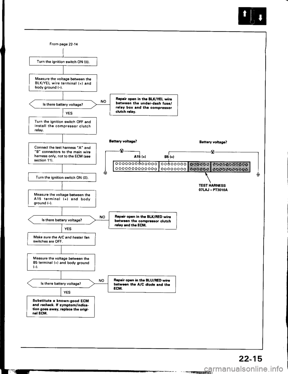
Frcm page 22-11
Bdt ry vohro.?
_@_____-l
Turn the ignition switch ON (lI).
M€asure the voltage betweon th6BLK/YEL wire terminsl {+) andbody ground (-).
R.p.i. opcn in th. 3LX/YEL wirrbalwarn tha undar.da3h tuaa/.clay box and iha como.aaao.clutch rahy.
ls there battery voltage?
Turn the ignition switch OFF andinstall the comprossor clutchrelay.
Connect the test harness "A" and"8" conoectors to th6 main wireharness only, not to the ECM (s6gsection 11).
Turn th6 ignition switch ON (II).
Measure the voltagG between theA15 terminal (+) and bodyground (-1.
R.prir op.n in th. BLK/RED wirtb.twran the compraa.or clotch..1.y .nd th. ECM.
Make sure the A/C and heate. tenswitch6s are OFF.
Measure tho voltage b€tween the85 terminsl (+) and body ground(-).
R.p.ir op.n in th. BI-U/RED wir.b.tw.rn th. A/C diod. .nd th.CCM.
Sub.titute r known-good ECMand rocheck. lt lymptom/indicr-tion go€3 rwry, rapbca th. origi-nrl ECM.
Blttary vohago?
r_--@_Bs {+)
TEST HARNESS07t4, - PT3010a
" , -1llltf,'tfrSfiiwiafi
22-15
Page 1084 of 1413
Troubleshooting
A/G System
10 page 22-17
A/C ay3t6m doe3 not como on(compro!3or and both f.ns).
Disconnect the A/C pressure
switch 2P connector.
Turn the ignition switch ON (II).
Measure the voltage beoveen the
BLU/RED wire terminal (+) and
bodv ground 1-).
Reprir opon in thc 8LU/RED wire
batwoan tho A/c prossute
rwitch rnd th. A/C diod..
Turn the ignition switch OFF.
Check lor continuity betwoen the
No. 1 and No. 2 terminals of the
A,/C pressure switch.
Check for NC system Pressure.
Reco n nect the A/C pressure
switch 2P connector.
Rophce tha A/C pre3!u.6 awitch.
View from wire side
YEL/WHTBLU/RED {+l
22-16
Page 1085 of 1413
From page 22-15
Turn the ignition switch ON (IIl.
Measure tho voltage betweon theBLK/YEL wire terminal (+) andbody ground (-).
R.p.i. op.n ir th. BLX/YEL wirobatwc.n tha unda.-darh fuao/r.l.y box .rd rh. A/C th.rmo.t!r.
Measure th€ voltage between theYEL/WHT wire terminal {+} andbody ground (-).
R.prir op.n in th. YEL/WHTwiro bctwaan tha A/C praaau.crwhch .nd th. A/C th..mo.ht.
ls there battory voltage?
T!rn the ignition switch OFF.
R€connect the Ay'C thermostat 3Pconn€ctor and connect the BLU/RED wire terminal to ground witha l!mper wire,
Do the radiator and con-donser fans run and thecompressor clutch engage?
Turn the ignition switch OFF anddisconn6ct the jumper wire.
YEL/WHT l+l
View from wir€ side
To page 22-18
(cont'd)
22-17
Page 1086 of 1413
Troubleshooting
Remove the heater control Panel(see page 21 25)
Disconnect the heater controlpanel 14P connector'
Turn the ignition switch ON (lI).
Measure the voltage between the
BLU/RED wire terminal (+) and
body ground { }
Rop.i. opon in tho BLU/BED wir.
b.twoon tha A/C thermort.t lnd
the haat.r control Panal
Turn the ignition switch OFF.
ls the A/C switch OK?
Check for continuitY in the GRN
wire between the heater controlpanel and the heater fan switch
R.prir op.n in the GRN wiro be'
twoen thc hartet contlol Panaland tho h.rtor fln switch.
Check for continuity in the BLK
wire between the heater {an
switch and body ground.
Chock fol an opon in the BLK
wi.a b.tween th. hotte. hn
lwitch tnd bodY ground. ll tho
wiro it OK, chock for Poorg.ound .t G4ol .nd G402.
Replace the heater lan switch.
Frcm page 22'17
View lrom wire side
A/C System (cont'dl
No. 11 BLU/RED l+l
22-18
Page 1091 of 1413

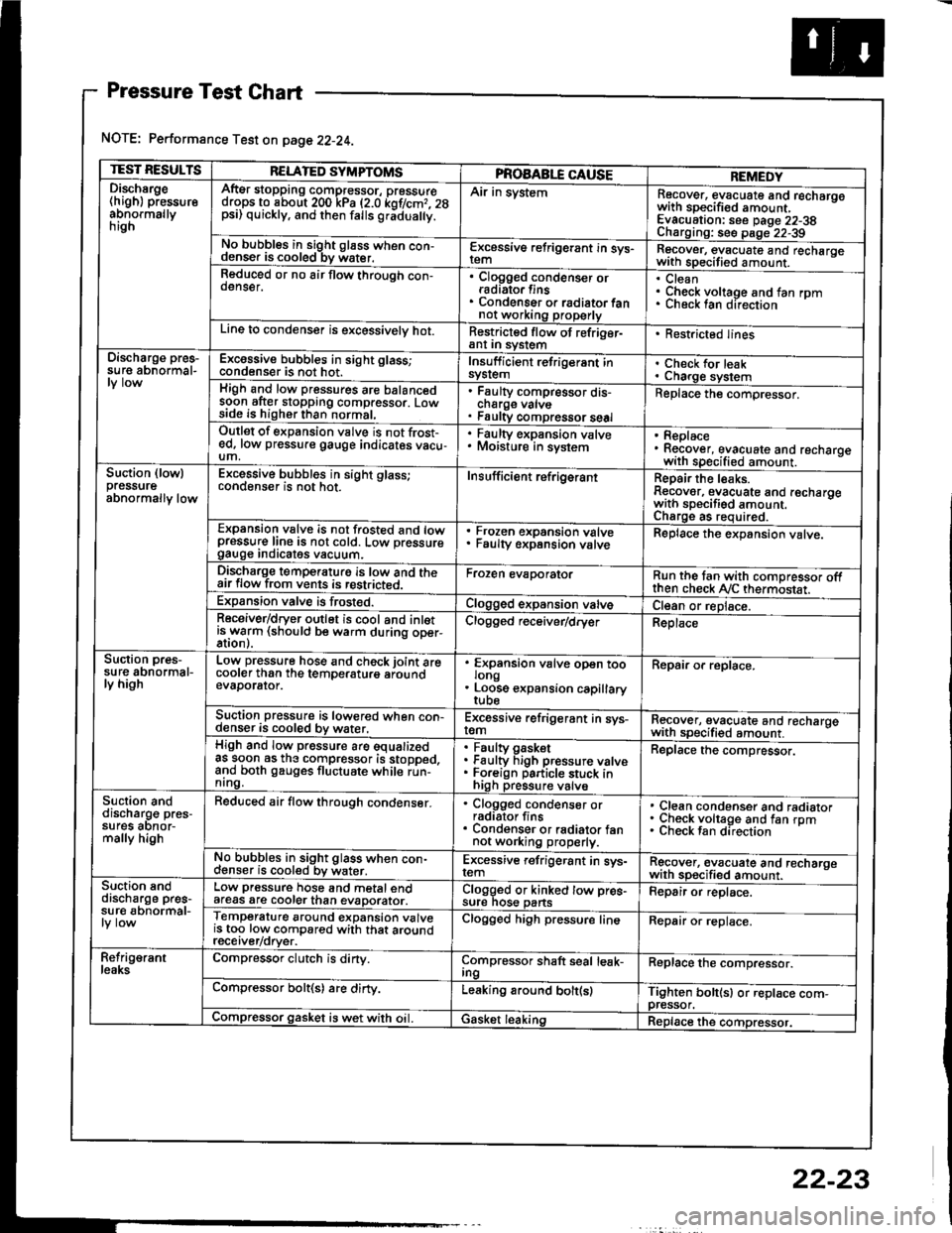
Pressure Test Chart
NOTE: Performance Test on page 22-24.
TEST RESULTSRELATED SYMPTOMSPROAABLE CAUSEREMEDYDischsrge(high) pressureabnormallynrgn
AftEr stopping compressor, pressuredrops to about 200 kPa (2.0 kof/cmr. 28psi) quickly, and then falls gr;dua y.
Air in systemRecover, evacuate and recharqowith sDecified amount. -
Evacuation: see Daqe 22-38Charoino: se6 D;op--2?-?qNo bubbles in sight g16ss when con-denser is cooled bv water.E-\cessive refrigerant in sys-Recover, evacuate and recharqewith specitied amount. -
Reduced or no air flow through con-oenser.Clogged condenser orradiato. finsCondenser o. radiator fannot working properly
CleanCheck voltage and fan rpmunecK lan ofeclton
Line to condenser is excessivelv hot.Restricted flow of refriger-ant In syslem. Restricted lines
Discharge pres-su re abnormal-Excossive bubbles in sight glass;condenser is not hot.Insuff icient refrigerant insyslemCheck for leakCharge systemHigh and low pressures are balancedsoon after stopping compressor. Lowside is higher than normal,
Faulty compressor dis-cnarge vaNsFaulty compressor seal
Replace the compressor.
Outlet of expansion vslve is not frost-ed, low pressure gauge indicates vacu-um,
. Faulty expansion valve. Moisture in sysiem. Replace. Recover, evacuate and recharoewith specified amount. -
Suction (lowlpressureabnormally low
Excessive bubbles in sight glass;conqenser rs not hot_Insuff icient ref rigerantReoair the leaks.Reaover, evacuate and recharoewith sDecifisd amount. -
Charqe as required.Expansion valve is not trosted and lowpressur€ line is not cold. Low pressuregauge Inorcates vacuum.
Frozen expansion valveFaulty expansion valveReplace the expansion valve.
Discharge temperaturg is low and theair flow from vents is restricted.Froren evaporatorRun the tan with comoressor oftthen check Ay'C thermostat.Expansion valve is frost€d.Clogged expansion valveCl€an or replace.Receiver/dryer outlet is cool and inletisrryarm (should be warm during oper-Clogged r€ceiver/dry€rReplace
Suction pres-su re abnormal-ly high
Low pressure hose and check joint arecooler than the temDeraturo aroundevaDorator.
'
ffin"nsion u"lu" oD"n too
. Loose expansion capillary
Repair or replace.
Suction pressure is lowered when con-denser is cooled by water,Excessive refrigerant in sys-remRecover, evacuate and recharqewith sDecifi€d amount. -
High and low pressure are equalizedas soon as the compressor is stopped,and both gauges fluctuate while run-nrng.
Faultv oasketFaulty Figh pressure valveForeign particle stuck inhigh pressure valve
Replace the compressor.
Suction anddischarg€ pres-sufes aonor-mally high
Reduced air flow through condenser.. Clogged condenser orradiator fins. Condenser or radiator fannot working properly.
Clean condenser and radiatorCheck voltage and fan rpmCheck fan direcrion
No bubbles in sight glass when con-cl€nser is cooled bv water.Excessive refrigerant in sys-remRgcover, €vacuate and recharoewith sp€cified amount.Suction snddischarge pres-su r€ abnormal-
Low pressure hose and metal endafeas are cooler than evaDorator.Clogged or kinked tow pre€-sure nos€ pansFepair or replace.
Temperature around expansion valveis too low compared with that aroundrecerver/orver.
Clogged high pressure lineRepair or replace.
Refrig€rantleaksCompressor clutch is dirty.Compressor shaft seal leak-IngReplace the comDressor.
Compressor bolt(s) are dirty.Leaking around bolt(s)Tighten bolt(sl or replace com-pressor.Compressor gasket is wet with oil. IGasket leakingReplace the compressor.
22-23