1994 HONDA INTEGRA starter
[x] Cancel search: starterPage 557 of 1413

20. Connect the vehicle speed sensor (VSS), mainshatt
speed sensor and counterchalt speed sensor con
nectors.
VEHICLE SPEED SEiISORCONNECTOR
21. Connect the lock-uD control solenoid valve connec-
tor and shift control solenoid valve connector. then
clamp the lock-up control solenoid harness with the
harness stay.
22. Connect the transmission ground cable.
LOCK-UP CONTROLSOLENOID VALVE HARNESS STAY
23. Connect the starter cable to the starter motor, and
install the cable holder.
NOTE: When installing the starter motor cable,
make sure that the crimped side of the ring terminal
is facing out (see section 23).
CABLEHOLDER
6x 1.0 mm'12 N.m (1.2 kgf'm,8.7 lbt.tl)
24.
N.mlO.9 ksr.m, 7 tbr-rtt
STARTER CAELE
Install the air cleaner housing assembly and intake
arr oucl.
AIR CLEANER HOUSINGASSEMBLYINTAKE AIRDUCT
25.
26.
24.
29.
30.
Retill the transmission with ATF(see page '14-93).
Connect the battery positive ( + ) and negative ( - )
cables to the battery.
Start the engine. Set the parking brake, and shift the
transmission through all gears three times.
Check shitr cable adjustment as described on page
14-171 .
Check that front wheel alignment (see section 18).
Let the engine reach operating temperature (the cool-
ing tan comes on) with the transmission in S or @position, then turn it off and check the fluid level.
31. Road test as described on page 14-9o and 91.
14-167
Page 1114 of 1413
![HONDA INTEGRA 1994 4.G Workshop Manual Relay and Control Unit Locations
Dashboard and Door
CRUISE CONTROL UNIT
PGM-FIMAIN RELAY
STARTER CUT RELAY IMIT)
I wir. colo]s: BLKMHT, BLU/BLK II BLKMHT ANd BLK/RED I
Wirs colors:WHT,GBN/BLK,GRN 6nd HONDA INTEGRA 1994 4.G Workshop Manual Relay and Control Unit Locations
Dashboard and Door
CRUISE CONTROL UNIT
PGM-FIMAIN RELAY
STARTER CUT RELAY IMIT)
I wir. colo]s: BLKMHT, BLU/BLK II BLKMHT ANd BLK/RED I
Wirs colors:WHT,GBN/BLK,GRN 6nd](/manual-img/13/6067/w960_6067-1113.png)
Relay and Control Unit Locations
Dashboard and Door
CRUISE CONTROL UNIT
PGM-FIMAIN RELAY
STARTER CUT RELAY IMIT)
I wir. colo]s: BLKMHT, BLU/BLK II BLKMHT ANd BLK/RED I
Wirs colors:WHT,GBN/BLK,GRN 6nd BLK
MOONROOF RELAYREAR wlNDOW DEFOGGERFELAY
I Wiro colo6: II BLKA'EL, BLK/GBN, I
I BLUffEL 8nd BLK^^THT I
POWER WINDOWRELAY
IIORN RELAY
J wi.o color3: WHT/GRN, BLx,l
I BLU/GBN, and BLU/RED I
INTEGRATEOCONTROL UNIT
TURN SIGI{AL/HAZARDRELAY UNDEB-OASHFUSE/RELAY 8OX
23-8
Page 1119 of 1413
Connector ldentification and Wire Harness Routing
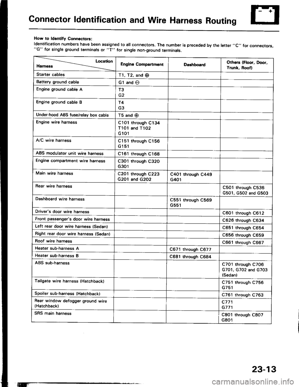
How to ldentity ConnoctolS:
ldentification numbers have been assigned to all connectors. The number is preceded by the letter ,,C,, for connecrors,"G" for single ground terminals ot "f" hr single non-ground terminals.
Location
HamessEngino CompartmontDarhboardOthors (Floor, Door,
Trunk, Rootl
Starter cablesT1, T2, and (E
Battery ground cableG1 and O
Engine ground cable AT3
Engine ground cable BT4
G3
Under-hood ABS fuse/relav box cableT5 and (D
Engine wire harnessC101 through C134
Tl Ol and T102
G 101
A/C wire harnessCl 5'l through C156
G151
ABS modulator unit wir€ harnessC161 through C168
Engine companment wire ha.nessC3O'l through C32O
G301
Main wire hatnessC2O1 through C223
G2Ol and G2O2
C4O1 through C449
G401
Rear wire harnessC501 through C536
G501, G502 and G5O3
DashboSrd wire harnessC551 through C569
G551
Driver's door wire harnessC601 through C612
Front passenger's door wire harnessC626 through C634
Left rear door wire harness (Sedan)C651 through C654
Right rear door wire harness (Sedan)C656 through C659
Roof wire harnessC661 through C667
Heater sub-harness AC671 through C677
Heater sub-hatness BC681 through C684
ABS sub-harnessC7O1 through C7O6
G7O1, G702 and G703(Sedan)
Tailgate wire harness (Hatchback)C751 through C756
Spoiler sub-ha.ness (Hatchback)C761 through C763
Rear window defogger ground wire(Hatchback)c77'l
G771
SRS main harnessC8O1 through C8O7
G801
23-13
Page 1120 of 1413
Gonnector ldentification and Wire Harness Routing
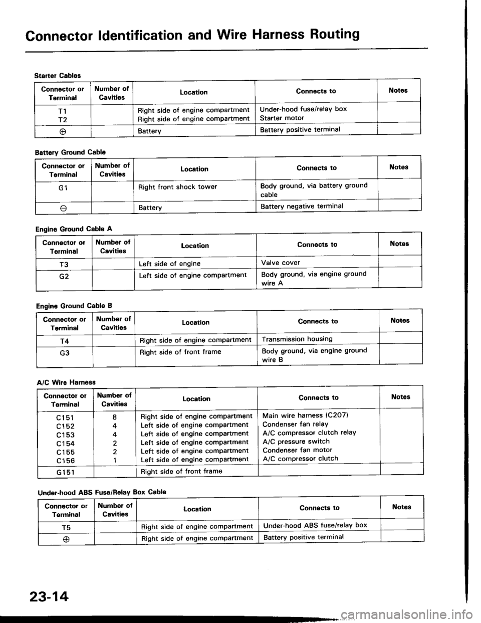
Startol cablos
Connector or
Terminal
Numbsr of
CavitiesLocationConnects toNotos
T1
r2
Right side of engine compartment
Right side of engine compartment
Under-hood fuse/relay box
Starter motor
@BatteryBattery positive terminal
B8ttory Ground Cable
Engine Ground Cable A
Engine Ground Cable B
A/C Wiro H81n6ss
Under-hood ABS Fus€/Relav Box Cablo
Conn€ctor or
T€rminal
Numbor of
CsvitiesLocationConnects toNotos
G1Right front shock towerBody ground, via battery ground
cable
\lBatteryBattery negative tetminal
Connoctor or
Tolminal
Number of
CavitiesLocationConnocta toNotes
T3Left side of engineValve cover
G2Left side of engine compartmentBody ground. via engine ground
wire A
Connoctor or
Torminal
Number ol
CavitiosLocationConnocts toNot€s
r4Right side of engine compartmentTransmission housing
G3Right side of front frameBody ground, via engine ground
wire B
Connoctor 01
Terminal
Numbor of
CavitiesLocationConnects toNotes
cl51
cl52
c153
c1 54
c155
c156
I
4
4
1
Right side ol engine comPartment
Left side of engine compartment
Left side of engine comPartment
Lett side ot engine compartment
Left side of engine comPanment
Left side of engine compartment
Main wire harness (C2O7)
Condenser fan relay
A/C compressor clutch relay
A/C pressure switch
Condenser fan motor
A/C compressor clutch
G151Right side of tront Jrame
Conngctor or
Terminal
Numbor ot
Caviti€sLocalionConnects loNotes
T5Right side of engine comPartmentUnder-hood ABS fuse/relay box
@Right side of engine compartmentBattery positive terminal
23-14
Page 1122 of 1413
Gonnector ldentification and Wire Harness Routing
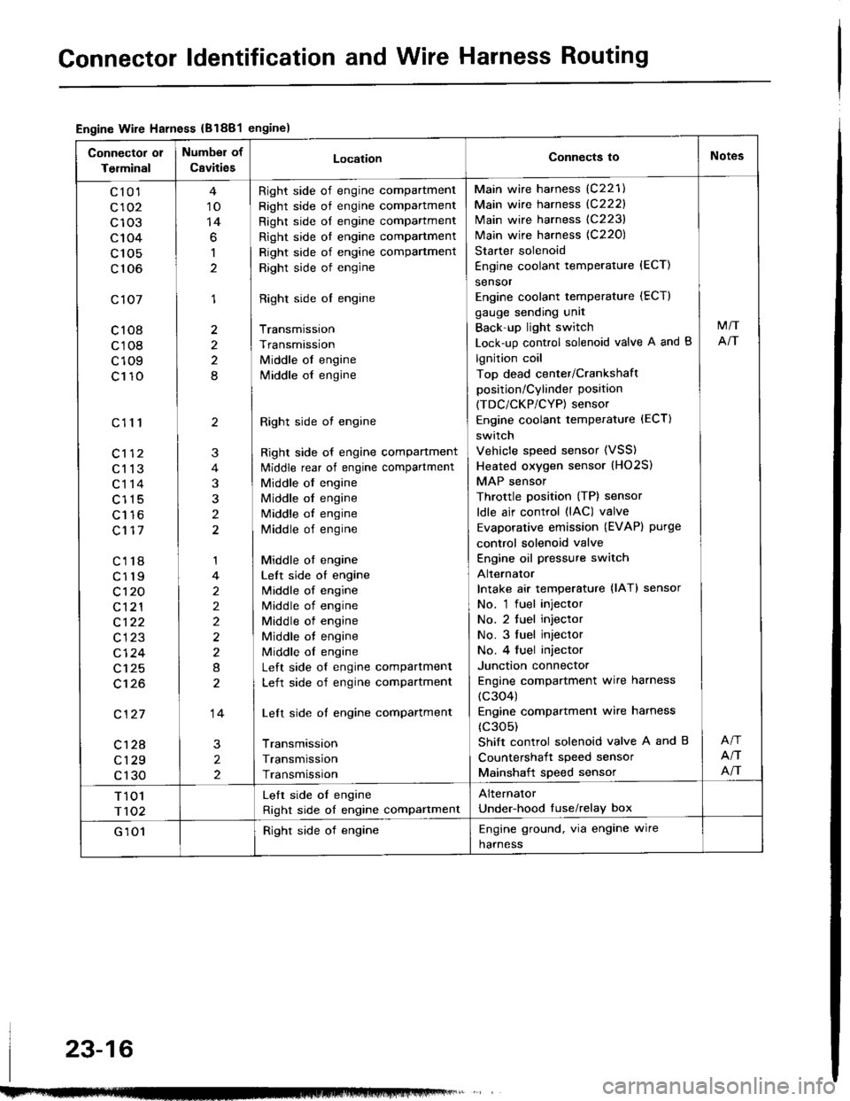
Engine Wire Harness {B1881engine)
Connector 01
Terminal
Number of
CavitiesLocationConnects ioNotes
c10'l
c102
c103
c104
c 105
c106
c107
c108
c108
c109
c110
c111
c113
c114
c115
Lt to
c117
c118
c119
c't 20
c121
c122
c123
cl24
c125
c't26
c127
c128
c129
c130
10
14
6
1
1
2
2
8
2
3
t
1
2
2)
2
8
14
2
2
Right side of engine compartment
Right side of engine compartment
Right side of engine compartment
Right side ol engine compartment
Right side of engine compartment
Right side of engine
Right side ol engine
Transmission
Transmission
Middle of engine
lvliddle of engine
Right side ot engine
Right side of engine compartment
ldiddle rear of engine compartment
Middle of engine
Middle ol engine
Middle of engine
Middle of engine
Middle ot engine
Left side of engine
lvliddle of engine
Middle of engine
Middle of engine
Middle ot engine
Middle ol engine
Left side of engine compartment
Left side of engine compartment
Left side of engine compartment
Transmission
Transmission
Transmission
Main wire harness (C221)
Main wire harness {C222}
Main wire harness (C223)
Main wire harness {C220)
Starter solenoid
Engine coolant temperature {ECT)
sensor
Engine coolant temperature (ECT)
gauge sending unit
Back'up light switch
Lock-up control solenoid valve A and B
lgnition coil
Top dead center/Crankshaft
position/Cylinder position
(TDC/CKP/CYP) sensor
Engine coolant temperature (ECT)
switch
Vehicle speed sensor (VSS)
Heated oxygen sensor (HO2S)
MAP sensor
Throttle position (TP) sensor
ldle air control (lAC) valve
Evaporative emission (EVAPI purge
control solenoid valve
Engine oil pressure switch
Alternator
Intake air temperature {lAT} sensor
No. 'l fuel injector
No. 2 tuel injector
No. 3 fuel injector
No. 4 fuel injector
Junction connector
Engine compartment wire harness
(c304)
Engine compartmenl wire harness
(c305)
Shift control solenoid valve A and B
Countershait speed sensor
Mainshaft speed sensor
M/T
NT
NT
NT
T 101
r102
Lelt side oI engine
Right side of engine compartment
Alternator
Under-hood tuse/relay box
G 101Right side of engineEngine ground, via engine wire
harness
23-16
Page 1124 of 1413
Gonnector ldentification and Wire Harness Routing
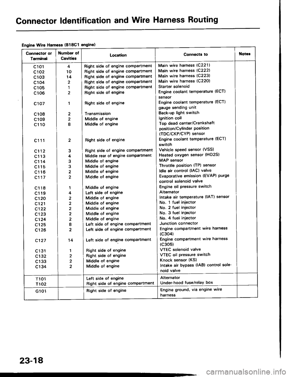
Engine Wire Harnoss (B18Cl enginol
Connoctor 01
Totminal
umbor ol
Cavitio8LocationConnecla tof{orc!
c 101
cl 02
c103
c104
c105
c106
c107
c108
c109
c110
c111
cl12
c113
c114
c115
c116
c117
c1r8
c119
c120
cl2'l
c122
c123
c124
c125
c't26
c'127
c 131
c132
c133
c134
2
J
4
3
'I
4
2
I
2
't4
1
4
10
14
,l
2
2
8
Right side of engine compartment
Right side of engine compartment
Right side ot engine comPanment
Right side of engine compartmsnt
Right side of engine compartment
Righr side ot engine
Right side of engine
Transmission
Middle ol engine
Middle oJ engine
Right side of engine
Right side ot engine comPartment
Middl€ reat of engine compartment
Middle of engine
Middle of engine
Middle ol engine
Middle o{ engine
Middle of engine
Lelt side ot engine
Middle of engine
Middle of engine
Middle ol engine
Middle ot engine
Middle of engine
Left side of engine companment
Lelt side ot engine compartment
Left side of engine compartment
Right side ot engine
Right sid€ of engine
Middle ot engine
Middle of engine
Main wire harness (C221)
Main wire harness (C222)
Main wire harness (C223)
Main wire harness (C22O)
Starter solenoid
Engine coolant temperature (ECT)
sensor
Engine coolant temperature {ECTI
gauge sending unit
Back-up light switch
lgnition coil
Top dead center/Crankshaft
position/Cylind€r Position(TDC/CKP/CYP) sensor
Engine coolant temperature {ECT)
switch
Vehicle speed sensor (VSS)
Hsated oxygen sensor {HO2S}
MAP sensor
Throttle position {TPl sensor
ldle air control (lAC) valve
Evaporative emission {EVAPI purge
control solenoid valve
Engine oil pressure switch
Alt€rnatot
Intake 8ir temperature (lAT) ssnsor
No. 1 fuel injector
No. 2 fuel iniector
No. 3 fuel injeclor
No. 4 fuel injector
Junction connector
Engine compartment ware harness
{c304)
Engine comPanment wire harness
(c305)
VTEC solenoid valve
VTEC oil pressure switch
Knock sensor (KS)
Intaka air bypass (lAB) control sole-
noid valve
T101
r102
Left side of engine
Right sid6 ot engine compartment
Alternator
Under-hood fuse/relay box
G 101Right side of engineEngine ground, via engine wire
harness
23-18
Page 1132 of 1413
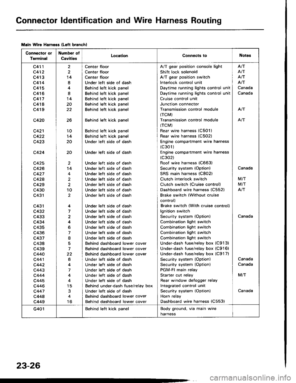
Connector ldentification and Wire Harness Routing
Msin Wiie Harness (Left branch)
Connector or
Terminal
Numbel ot
CavitiesLocationConnects toNotes
c411
c412
c413
c414
c415
c416
c4'17
c418
c419
c420
c42'l
c423
c424
c425
c426
c427
c42A
c429
c430
c431
c43l
c432
c433
c434
c435
c436
c437
c438
c439
c440
c44'l
c442
c443
c444
c445
c446
c447
c448
c449
26
10
20
20
14
8
4
I
14
20
22
't4
4
2
10
4
7
4
o
7
I
7
22
6
4
7
4
15
to
Center floor
Center floor
Center floor
Under left side ot dash
Behind left kick panel
Behind left kick panel
Behind left kick panel
Behind left kick panel
Behind left kick panel
Behind left kick panel
Behind left kick panel
Behind left kick panel
Under left side of dash
Under left side of dash
Under lett side of dash
Under left side ot dash
Under lett side of dash
Under lett side of dash
Under lett side of dash
Under lett side of dash
Under lett side ot dash
Under left side of dash
Under left side ol dash
Under left side of dash
Under left side of dash
Under left side of dash
Under left side of dash
Under left side of dash
Behind dashboard lower cover
Behind dashboard lower cover
Behind dashboard lower cover
Under left side of dash
Under left side of dash
Under left side of dash
Under lett side of dash
Under left side of dash
Behind under-dash fuse/relay box
Under left side ot dash
Behind dashboard lower cover
Behind dashboard lower cover
A/T gear position console light
Shift lock solenoid
A/T gear position switch
Interlock control unit
Daytime running lights control unit
Daytime running lights control unil
Cruise control unit
Junction connector
Transmission control module
(TCM)
Transmission controi module
{TCM)
Rear wire harness (C501)
Rear wire harness {C502)
Engine compartment wire harness
(c301)
Engine compartment wire harness
(c302)
Roof wire harness (C663)
Security system (Option)
SRS main harness (C802)
Clutch interlock switch
Clutch switch (Cruise control)
Dashboard wire harness (C552)
Brake switch (Without cruise
control)
Brake switch (With cruise control)
lgnition switch
Security system (Option)
Combination light switch
Combination light switch
Combination light switch
Combination light switch
Under-dash fuse/relay box {C9131
Under-dash fuse/relay box {C9161
Underdash tuse/relay box (C9'l 7l
Security system (Option)
Security system {Option)
PGM-FI main relay
Starter cut relay
Rear window defoqger relay
Integrated cont.ol unit
Security system {Option)
Horn relay
Dashboard wire harness (C553)
Afi
AiT
Afi
Afi
Canada
Canada
Arf
An
Canada
Canada
M/T
M/T
Atr
Canada
Canada
M/T
Canada
G401Behind left kick panelBody ground, via main wire
harness
23-26
Page 1179 of 1413
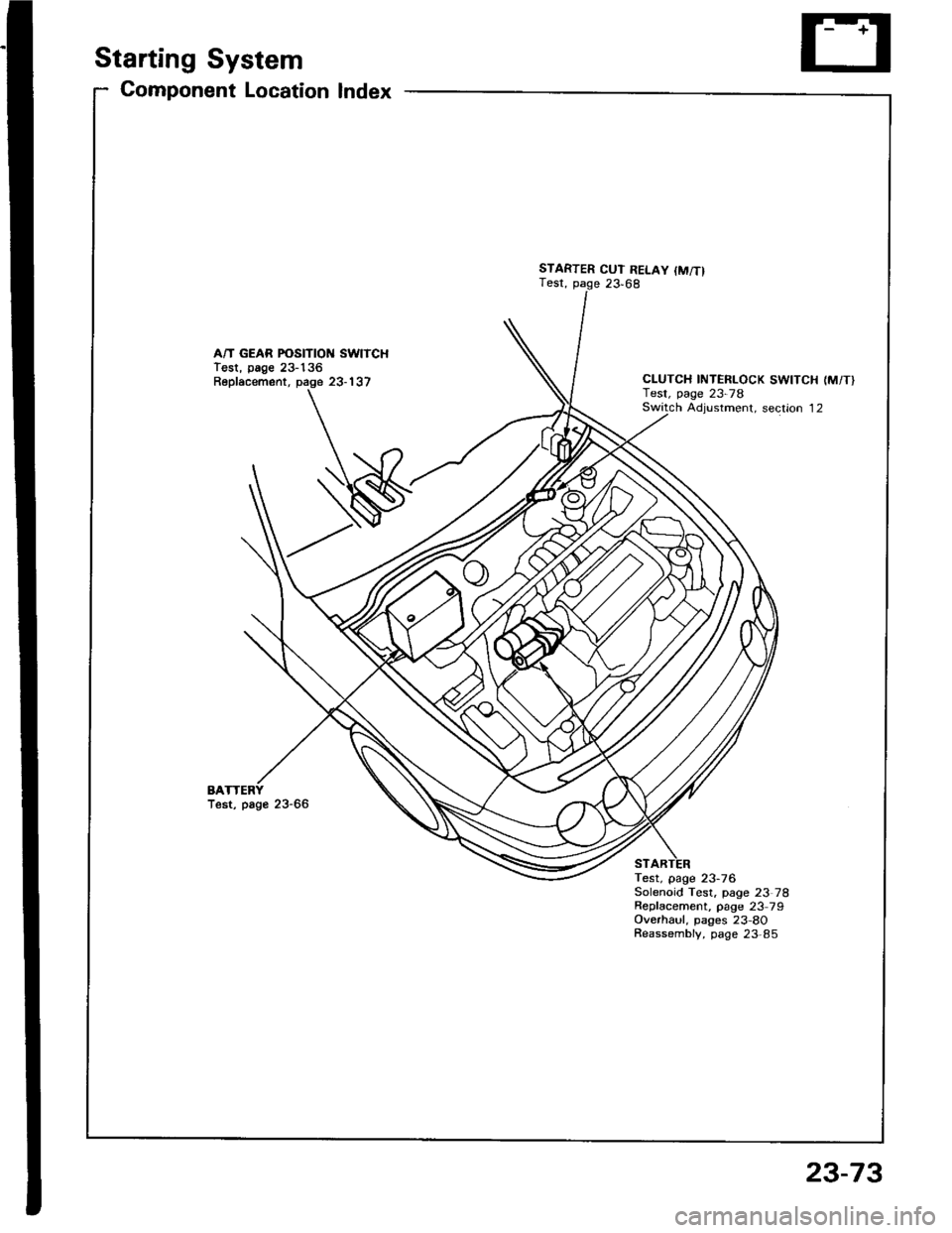
Starting System
Gomponent Location Index
A/T GEAR POSITION SWITCHTest, page 23-136Replacement, page 23-137
BATest, page 23-66
STARTER CUT RELAY {M/T}Test, page 23,68
CLUTCH INTERLOCK SWITCH (M/T}Test, page 23-78Switch Adiustment. section 12
Test, page 23-76Solenoid Test, page 23 78Repfacement, page 23 79Overhaul, pages 23-8OReassembly, page 23,85
23-73