Page 485 of 1413

Fluid Level
Checking/Changing
Checking
NOTE: Check the fluid level with the engine at normal
operating temperature (the cooling lan comes on).
1. Park the car on level ground. Shut otf the engine.
2. Remove the dipstick (yellow loop) from the trans-
mission, and wipe it with a clean cloth.
3. Insert the dipstick into the transmission.
DIPSTICK (YELLOW LOOPI
4. Remove the dipstick and check the fluid level.
should be between the uoDer and lower marks.
P
il
\---
T
lf the level is below the lower mark, add fluid into
the tube to bring it to the upper mark. Use Honda
Premium Formula Automatic Transmission Fluid or
anequivalentDEXRON@ llAutomaticTransmission
Fluid (ATF) only.
lnse.t the diDstick back into the transmission.
IT
{J. UPPER MARK
t)-i- LowER MARK
5.
6.
Changing
1. Bring the transmission up to operating temperature
by driving the car. Park the car on level ground, turn
the engine oft, then remove drain plug.
NOTE: lf a cooler flusher is to be used, see page
14-168 and 169.
2. Reinstail the drain plug with a new sealing washer,
then refillthe transmission to the upper mark on the
dipstick.
Automatic Transmission Fluid Capacity:
2.1 | l2.S US qt, 2.4 lmp qt) at change
5.9 ? (6.2 US qt, 5.2 lmp qt) at overhaul
18 x 1.5 mm49 N.m (5.0 kgl.m, 36 lbl.ft)
TRANSMISSION RIGHT SIDE COVER
14-93
Page 486 of 1413

Pressure Testing
a While testing, be caretul of the rotating flont wheels.a Make aura litts, jacks, and sat€ty stands alo placedplop6rly {see section 1}.
CAUTION: Betore t€sting, be sure the transmission fluidis tilled to rh6 ploper l€vet.
1. Raise the car (see section i),
2. Warm up the engine {the cooling fan comes onl, thenstop the engine and connect a tachometer.
3. Connect the oil pressure gauge to each inspectionholels).
TOROUE: 18 N.m (1.8 kgf.m, 13 tbf.fr)
CAUTION: Connect ths oil prsssure gauge s€cur€_ly; be sule not to allow dust and other foleign pani_cl6s to 6nt€1 th€ inspection holo.
A/T OIL PRESSURE GAUGESET WPANEL07406-002oi+oo
A/T LOW PRESSUREGAUGE W/PANEL07/rO6-0O70300
A/T OIL PRESSURE HOSE,22'10 mmOTMAJ_PY4OI TA{4 Roquirod)
A/T OIL PRESSUBE HOSEADAPTEROTMAJ - PY/+O12014 Roqui.odl
NOTE: Use the A/T Oil Pressure Gauge Set (07406_O02OOO3) or A/T Low Pressure Gauge (07406-OOTO0OO). and the oil pressure gauge hoses and adap_ters shown above.
14-94
4. Start the engine, and measure the respective pres-
sure as follows.
a Line Pressure
a Clutch Pfessure
a Clutch Low/High Pressure
a Throttle B Pressure
5. Install a new washer and the sealing bolt in the in-spection hole and tighten to the specified torque.
TOROUE: 18 N'm {1.8 kgf.m, 13 tbf.ft)
NOTE: Do not reuse old aluminum washers.
a Line Pressure M€asurement
- 1 . Set the parking brake and block both rear wheelssecurely.
-2. Run the engine at 2,OOO rpm
-3. Shift the selecr lever to S or @ position.
-4. Measure line pressure.
LINE PRESSUREINSPECTION HOLE
NoTE: Higher pressures may be indicated it measurements are made in selector positions other than @ or @ position.
PRESSURESELECTOR
POStTTONSYMPTOMPROBABLE CAUSEFLUID PRESSURE
StandardService Limit
LineNo'ENo (or low)
lrne pressureTorque converter,
orl pump, pressure
regulator, to.que
convener check
valve
83O-88O kPa(8.5-9.O kgf/cm,,
120- I 30 psi)
78O kPa
{8.0 kgl/cm,, 1lO psi}
Page 564 of 1413
Throttle Control Cable
Inspection
NOTE: Betore inspecting the throttle control cable, make
sure:
a Throttle cable free play is correct (see section 1 1).
a ldle speed is correct (see section 1l).
a To warm up the engine to normal operating tempera-
ture {the cooling fan cor'res on)
1 . Verify that the throttle control cable is clamped cor-
rectly with three positions.
14-174
Verify that the throttle control level is synchronized
with the thronle linkage while depressing and releas-
ing the accelerator pedal.
lf the throttle control lever is not synchronized with
the throttle linkage. adjust the throttle control cable.
\
,r:
Page 566 of 1413
Throttle Control Cable
Adjustment
NOTE: Before adjusting ths throttle control cable, makesute:
a Throttle cable free play is correct {see section 11).a ldle speed is correct (see section 11).a To warm up the engine to normal oporsting tempera-ture {the cooling lan comes on}.
I . Verify that the throttle control c8ble is clamDed cor-rsctly with three positions.
THROTTLECOI{TROL CABLEATF COOLERPIPE
5.
CLAMP
Verify that the throttle linkage is in the full-closedposition.
Loosen the locknut of the throttle control cable atthe throttle linkage.
Clamp on blu6
THROTTLE LII{KAGE
LOCKI{UTS
14-176
4. Remove the free play of ths throttl6 control cabl€with the locknut, whils pushing thg throttlo controlleve. to the full-closed Dotision as snown,
5. Tighten the locknuts.
After tightening the locknuts, inspect the synchroni-zation and throttlg control l6ver movemenr.
Page 1075 of 1413

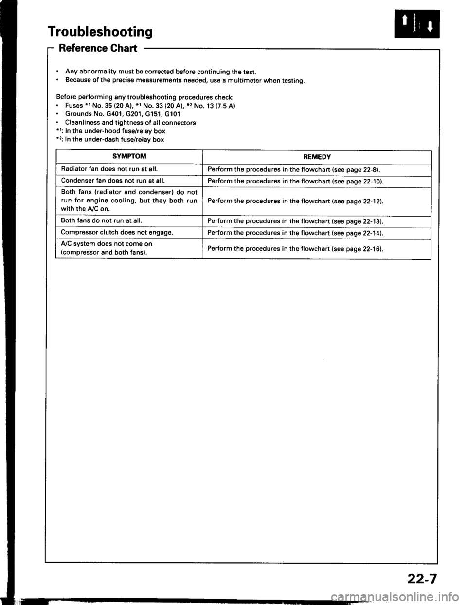
Troubleshooting
Reference Ghart
. Any abnormality must be correctsd before continuing the test.. Because of the precise measurgments needed, use a multimeter when testing.
Before performing any troubleshooting procedures check:. Fus€s .r No. 35120 A), *1 No. 33 (20 A), ), No. 13(7.5A). Grounds No. G401, G201, G'151, G101. Cleanliness and tightness of all connectors*1: In the under-hood fuse/relay box*2: In the under-dash fuse/relay box
SYMPTOMREMEDY
Radiator fan does not run 8t all.Perform the procedures in the flowchan (see page 22-8).
Condenser fan does not run at all.Perform the procedures in the flowchart (see page 22-10).
Both fans (radiator and condenser) do not
run for engine cooling, but they both run
with the Ay'C on.
Perform the procedures in the flowchan (see page 22-12).
Eoth fans do not run at all.Perform the procedures in the flowchart (see page 22-13).
Compressor clutch does not engage.Perform the procedures in the flowchart (see page 22-14).
Ay'C system does not come on
{compressor and both fans}.Perform the procedures in the flowchart (see page 22-16).
22-7
Page 1080 of 1413
Troubleshooting
Bolh tanr lradiltor and con-
dan.arl do not run fot anginacooling. bul th.y bolh tun whh
th. A/C on.
Disconnect tho engino coolanltemporsture (ECT) switch 2P con-
n6ctor.
Turn rhe ignition switch ON (ll).
Measure th€ voltago botw€en th6
cRN wire terminal (+) and bodyground {-}.
R.p.ir op.n in ih. GRN wir. b.-
tw..n th. ECT .wilch .nd th.
undrr.hood ful./t l.y box.
Turn the ignition switch OFF and
check lor continuity in the BLK
wire beMeen the ECT switch and
body ground.
Ch.ck tor.n op.n in th. BLK
wir. b.lw.!n th. ECT .witch.nd body ground. It th. wit. i.
OK, chacl lor poor Oround tt
G10r.
Do€s it road above normal?
22-12
Page 1203 of 1413

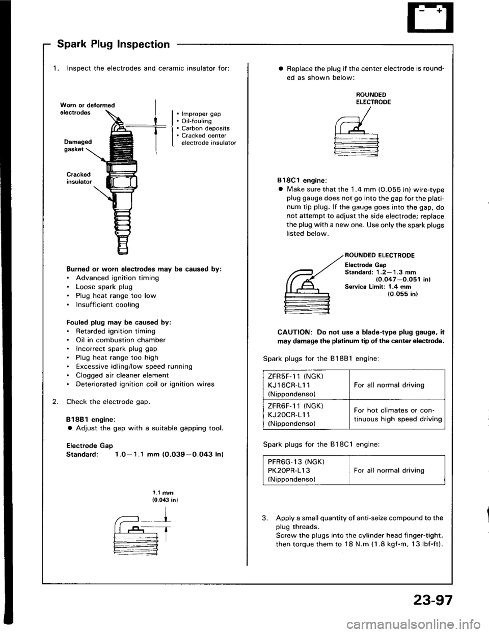
Spark Plug Inspection
1. Inspect the electrodes and ceramic insulator for:
. rmproper gap. Oil-touling. Carbon deposits. Cracked centerelectrode insulatorDamagedgask6t
Burned or worn electlodes may be caused by:. Advanced ignition timing. Loose spark plug. Plug heat range too low. Insufficient cooling
Fouled plug may be caused by:. Retarded ignition timing. Oil in combustion chamber. lncorrect spark plug gap. Plug heat range too high. txcessive idling/low speed running. Clogged air cleaner element. Deteriorated ignition coil or ignition wires
Check the electrode gap.
Bl88l engine:
a Adjust the gap with a suitable gapping tool.
Electrode Gap
Standard: 1.0-1.1 mm (O.O39-0.O43 in)
1.1 mm{0.0,$ in)
Replace the plug if the center electrode is round-
ed as shown below:
ROUNDEDELECTROOE
Bl8Cl engine:
a Make sure that the '1.4 mm (0.055 in) wire-typeplug gauge does not go into the gap for the plati-
num tip plug. lf the gauge goes into the gap, do
not attempt to adjust the side electrode; replace
the plug with a new one. Use only the spark plugs
listed below.
ROUNDEO ELECTRODE
Electrode GapStandard: 1 .2-'l .3 mm{0.047 -O.051 in)Service Limit: 1.4 mm{0.055 in)
CAUTION: Do not use a blade-type plug gaugs, it
may damage the platinum tip of the center olectrodo.
Spark plugs for the 81881 engine:
Spark plugs for the B'l8Cl engine:
PFR6G_13 (NGK) IPK2OPR-113 I For all normal driving
{Nippondenso)
3. Apply a small quantity ol anti-seize compound to the
plug threads.
Screw the plugs into the cylinder head iingef-tight,
then torque them to 18 N.m (1.8 kgf.m, 13lbf.ft).
ZFRsF-1 1 (NGK)
KJl6CR-11 1
(Nippondenso)
For all normal driving
ZFR6F-1 1 (NGK)
KJ2OCR-11 1(Nippondenso)
For hot climates or con-
tinuous high speed driving
23-97
Page 1218 of 1413
Fan Controls
Fan Motor Test
1. Disconnect the 2-P connector from the fan motor.
2. Test the motot by connecting battery power to the
B terminal, and ground to the A terminal
3. lf the Jan motor fails to run smoothly, replace it.
NOTE: The illustration shows the radiator fan.
Engine Coolant Temperature (ECT)
Switch Test
NOTE: Bleed air from the cooling system atter install-
ing the engine coolant temperature (ECT) switch (see sec-
tion 1O).
1. Remove the ECT switch from the thermostat
housing.
2. Suspend the ECT switch in a container of coolant
as shown.
Heat the coolant and check engine coolanl tempera-
ture with a thermometer.
Check the continuity between the A and B terminals
according to the table:
Terminal
;;,".,"---\
B
Switch
Above 196 2O3"F
{91-95'C)o_-o
Below 181- 189oF
(83-87'C)
23-112
Page:
< prev 1-8 9-16 17-24