Page 346 of 1413
Transmission Assembly
Removal
Mskc aurs iack! and safoty Etands aro placod proper-
ly lsl8 saqtion 1|.
Apply parking brake tnd block rear whccl! to car
will not roll ofl stand3 and f.ll on you while wotking
undrr it.
CAUTION: Use tondcr coyar3. to avoid drmlging
plintsd 3qrfaca3,
Disconn€ct the negative {-) cable from the battery,
then the positive (+) cable.
Drain the transmission oil, then reinstall the drain
plug with a new washer (see page 13-3),
Remove the intake air duct and the air cleaner hous-
ing assembly,
AIR CITANERHOUSING
13-4
4. Disconnect the back-up light switch connoctor and
the transmission ground wir€.
5, Remove the lower radiator hose clamp trom ths
transmission hanger B.
BACK.UP LGHTsuTcH cot{t{EcToR
lnaNsMttistoNGROUND WIRE
tnaNsi ssloNHANGEB B
o.
1.
R€move the wire harness clamPs.
Disconnect the stsrt€r motor cables and the vahicla
soeed sensor (VSS) connector.
VSS OONNECTOR
Page 350 of 1413
lllustrated Index
Refer to the drawing below for the transmission disassembly/reassembly.
Clean all the parts thoroughly in solvent and dry with compressed air.
I ruurlcate att the parts with oil before reassembly.
NOTE:
. This transmission uses no gaskets between the major housings; use liquid gasket (P/N 08718-0001)
{see page 13-43).
a
a
Alwavs clean the magnet @ whenever the transmission housing is disassembled.
Inspect all the bearings for wear and operation.
(9
@
@
tqqlnl^'1ult I Ej
nl
11-4fi
,\|j Uh
o
@
o
@@
@
@
(3
(,
@
@
@
a
@
@
@
@
B
tg
Y
o
@
@
@
*N
13-8
[@.--oaF5i,--@:7
Page 351 of 1413

12 N.m (1.2 kgim,9 lbnft)
15 N.m (1.5 kgnm, 11 lbf.ft)
15 N.m (1.5 kgf.m, 11 lbf.ft)
24 N.m (2.4 kgf.m, 17 lbf'ft)
27 N.m (2.8 kgnm,20 lbnft)
30 N.m (3.1 kgf.m, 22 lbf'ft)
Bolt Size
,l
{
@@69
@
@@@@@@@@6Dq0
o€xv0@
@0!@@@@al
61@
B
c
D
E
F
6x1.0mm
6x1.0mm
I x 1.0 mm
8 x 1.25 mm
8 x 1.25 mm
8 x 1.0 mm
i) BALL BEARINGe sroPPER R|NG9 TAPER RINGA NEEDLE EEARINGO SPACER.d SYNCHRO RINGt sYNcHRo SPR|NG!) 5TH/REVEFSE sYNcHRo SLEEVEO 5TH/REVERSE SYNCHRO HUB[0 sYrucxao nlrucii i) 5TH GEARO 38 x 43 x 26 mm NEEDLE BEARINGt3 SPACEE COLLARO 4TH GEAR.iB SYNCHRO FING.Ii9 SYNCHRO SPRING{, 3RD/,ITH SYNCHRO HUB
@ 3RD/4TH SYNCHBO SLEEVEt9 3RD GEARO MAINSHAFTO wasHER@) SPRING WASHER40 BALL BEARINGO 28 x 41 x ? mm OIL SEAL Replace.ad 35 x 56 x 8 mm OIL SEAL Replace.a0 14 x 20 mm OOWEL PIN@ OIL CHAMBER PLATE'A BEVERSE IDLEN GEAR SHAFT@ wasHER t-2).A REVERSE IDLER GEAFO REVERSE CHANGE HOLDER3A sTH/REVERSE SHIFT PIECEO 1ST/2ND SHIFT FORK04 3RD/.TH sHlFr FoRK@ 5TH/REVERSE SHIFT FORKO9' OIL GUTTER PLATE6' SNAP RING@ 72 mm THRUST SHIM) OIL GUIOE PLATEi!0 10 mm WASHER Replace..4i] REVERSE IDLER GEAR SHAFT BOLT54 N.m {5.5 kgt m, 40lblftl) TRANSMISSION HANGER B(3 BREATHER CAP@ TRANSMISSION HANGER A63 BACK.UP LIGHT SWITCH25 N.m (2.5 ksf.m, 18lbfftl@r 14 mrn waSHER Replace.67 16 mm SEALING BOLT29 N.m (3.0 kgl.m, 22 lbf ft)@ 32 mm SEALING BOLT25 N.m (2.5 kgf.m. 18lbt'ft|@ 40 x 62 x 9 mm OIL SEAL Replace.D STEEL BALL D. 5/16 inGl SPRING L. 30 mm {1.2 in}
@ 12 mm WASHER Replace.63) SET SCREW22 N.m 12.2 kgl.m, 16 lbt'ft,@ OIL ORAIN PLUG39 N.m {4.0 kgt.m, 29 lbf'ftl€9 WASHER Replace.@ oIL FILLER PLUG4,1N.m 14.5 kgJ m, 33 lblftl
*1:81881 engine*2:B18Cl engine
WASHER Beplace.TRANSMISSION HOUSING80 mm SHIM (*1)79.5 mm SHIM {*21THRUST SHIM {*2IT. 2.0 mm (0.079 in)BEARING OUTER RACE {*2}SHIFT PIECE SHAFTINTERLOCKSHIFT PIECESHIFT ARM HOLDERSELECT ARMSELECT RETURN SPRING10 mm SHIM10 mm WASHERLOCK COLLAR3 x 16 mm SPRING PIN Replace.8 mm SPRING WASHERCHANGE PIECESET SCREW22 N.m {2.2 kgf.m, 16 lbf.ft}SPRING L.25.6 mm {1.01 inlSTEEL BALL D. 5/16 inMAGNETCLUTCH HOUSING14 x 25 x 16 mm OIL SEAL Replace.SHIFT RODDIFFERENTIAL ASSEMBLYSee section 15BEARING OUTER RACE I*2ITHRUST SHIM I*2)T. 2.5 mm (0.098 in,SHIFT ROD BOOTOIL GUID€ PLATE33 x 60 x 20 mm NEEDLE BEARINGBEARING RETAINER PLATELOCK WASHER Replace.COUNTERSHAFTTHRUST SHIM37 x 42 x 25 mm NEEDLE BEARINGlST GEARFRICTION DAMPERSYNCHRO RINGSYNCHRO SPRINGlST/2ND SYNCHRO HUBREVERSE GEARDOUBLE CONE SYNCHRO I*2ISYNCHRO BING I*1)FRICTION DAMPERSPACER42 x 6? x 24 mm NEEDLE BEARING2ND GEAR3RD GEAR4TH GEAS5TH GEARNEEDLE BEARINGBALL BEARINGSPRING WASHERLOCKNUT Replace.108 - 0- 108 N.m(11.0 - 0* 11.0 kgt m,80- 0- 80lbf.ft)5 x 22 mm SPRING PIN Replace.00
13-9
Page 353 of 1413
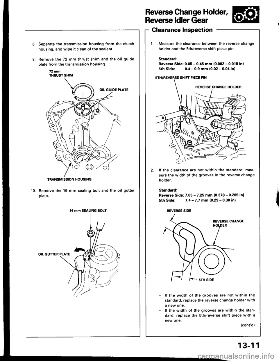
Reverse Change Holder,
Reverse ldler Gear
Clearance Inspection
Measure the clearance between the re
holder and the sth/revsrse shift piece p
Standard:
Bevorse Sido: 0.05 - O.ils mm (0.002 - (
5th Sido: o.ia - 0.9 mm 10.02 - 0.0,1
SHIFT PIECE PIN
REVERSE CHANGE
€,
lf the clearance are not within the sti
sure the width of the grooves in the re
holder.
Standsrd:
Rovsrea Side: 7.05 - 7.25 mm {0.278 - (
sth Sido: 7.1-7.7 mm (0.29 - 0.30
REVERSC SIOE
REVERSE
I ' '-- sTH SIDE
lf the width of the grooves are n
standard, replace the reverse chan€
a new one.
lf the width of the grooves are wi
dard, replace the sth/reverse shift
new one,
Separste the transmission housing from the clutch
housing, and wipe it clean of the sealant.
Remove the 72 mm thrust shim and the oil guide
plate from the transmission housing.
t2 mmTHRUST SHIM
TRANSMISSION HOUSING
Remove the 16 mm sealing bolt and the oil gutter
plate.
OIL GUTTER PLATE
10.
reverse cnange
ptn.
.0.018 inl
),1in)
standard, mea-
reverse change
0.285 in)
I inl
not within the
Inge holder with
within the stan-
rift piece with a
(cont'd)
13-1 1
Page 380 of 1413

Mainshaft Thrust Glearance
1. Remove the 72 mm thrust shim and oil guide plate
from the transmission housing.
72 mm THRUST SHIM
TRANSMISSIONHOUSINGOIL GUIDE PLATE
Adjustment
\.u
o
Bo
lnstall the 3rd/4th synchro hub, spacer collar, sth
synchro hub, spacer, and ball bearing on the main-
shaft. then install the above assembly in the trans-
mission housing.
Installthe washer on the mainshaft.
Measure distance @ between the end of the trans-
mission housing and washer.
NOTE:
. Use a straight edge and vernief caliper.
. Measure at three locations and averaoe the read-
Ing.END olTRANSMISSIONHOUSINGMAINSHAFT
WASHER
fr
13-38
AALL AEARING
. Try the 1.68 mm (0.0661 in) shim.
5. Measure distance @ betlveen the end of the clutch
housing and bearing inner race.
NOTE:
. Use a straight edge and depth gauge.
a Measure at three locations and average the read-
Ings.
Select the prcpet 72 mm thrust shim from the chart
by using the formula below.
NOTE: Use only one 72 mm thrust shim.
Shim Sslsction Formula:
From the measurements you made in steps 4 and 5:-1. Add distance @ (step 5lto distance @ (step 4).
-2. From this number. subtract 0.93 (which is the
midpoint of the flex range of the clutch housing
bearing spring washerl.
-3. Take this number and compare it to the avaif
able shim sizes in the chart.
(For example)
B:2.39
+ C: O.22
2.61- 0.93
1.68
END of CLUTCH HOUSING
INNEB RACE ot BALL BEARltac
Page 381 of 1413

72 mm Thrust Shim
Part NumberThickness
23931 - P21 -0000.60 mm (0.0236 in)
23932-P21 -0000.63 mm (0.0248 in)
c23933 - P21 -0000.66 mm {0.0260 in}
D23934-P21 -0000.69 mm (0.0272 in)
23935 - P21 -0000.72 mm (0.0283 in)
F23936-P21 -0000.75 mm (0.0295 in)
23937-P21 -0000.78 mm (0.0307 in)
23938-P21 -0000.81 mm (0.0319 in)
23939-P21 -0000.84 mm (0.0331 in)
J23940-P2r-0000.87 mm (0.0343 in)
K23941 - P21 -0000.90 mm (0.0354 in)
L23912-P21-OOO0.93 mm (0.0366 in)
M23943-P21 -0000.96 mm (0.0378 in)
N23944-P21 -0000.99 mm (0.0390 in)
o23915 - P21 -0001.02 mm (0.0402 in)
P23946 - P21 ,0001.05 mm (0.04'13 in)
o23947 -P21 -0001.08 mm (0.0425 in)
23948 - P21 0001.11 mm {0.0437 in}
s23919-P21 -0001.14 mm (0.0449 inl
T23950-P21 -0001.17 mm (0.0461 in)
23951 - P21 -0001.20 mm {0.0472 in)
23952 - P21 0001.23 mm {0.0484 in)
23953-P21 -0001.26 mm (0.0496 in)
X23954-P2r-0001.29 mm 10.0508 in)
23955-P21 -0001.32 mm 10.0520 in)
z239s6-P21 ,0001.35 mm (0.0531 in)
23957-P21 -0001.38 mm (0.0543 inl
AB23958 - P21 -0001.41 mm (0.0555 in)
AC23959 - P21 -0001.44 mm (0.0567 in)
AD23960 - P21 -0001.47 mm (0.0579 in)
AE23961 -P21 -0001.50 mm {0.0591 in)
23962 P21 ,0001.53 mm {0.0602 in)
23963-P21 -0001.56 mm {0.0614 in}
AH23964 - P2'1 -0001.59 mm (0.0626 in)
AI23965 - P2'1 -0001.62 mm (0.0638 in)
23966-P21 -0001.65 mm (0.0650 in)
AK23967-P21 -0001.68 mm {0.0661 in)
23968 - P21 -0001.71 mm 10.0673 in)
23969 - P21 0001.74 mm (0.0685 in)
AN23970-P21 -000'1.77 mm (0.0697 in)
AO23971 P21 0001.80 mm (0.0709 in)
7. Check the thrust clearance in the manner described
below.
NOTE: Carry out the measurement at normal room
remperarure.
-1. Install the thrust shim selected and oil guide
plate in th€ transmission housing.
?2 mm THRUSTotLPLATE
TRANSMISSIONHOUSING
Install the spring
ball bearing.
washer and washer on the
NOTE:
. Clean the spring washer, washer and thrust shim
throughly before instaliation.
. Install the spring washer. washer and thrust
shim properly.
a-=s-.r*os".^
.,,-B*^INGWASHER
-4.
Installthe mainshaft in the clutch housing.
Place the transmission housing over the main-
shaft and onto the clutch housing.
Tighten the clutch and transmission housings
with severalS mm bolts.
NOTE: lt is not necessary to use sealing agent
between the housings.
8 x 1.25 mm
27 N.m {2.8 kgf.m, 20 lbf.ft}
Tap the mainshaft with a plastic hammer,
(cont'd)
13-39
Page 383 of 1413
Transmission
;
ReassemblV
1. lnstallthe new oil seal.
2. Set the change Piece.
3. lnstall the shift rod.
4 Installthe steel ball, the spring, and the set screw.
5. lnstall the change piece attaching bolt.
6. Install the shift rod boots.
8x1.0mm30 N.m 13.1 kg{ m.
SET SCREW12 x'1.0 mm22 N.m {2.2 kg{.m, 16lbl.ft}
SPRINGL. 25.6 mm22 tbl.ltl
Installthe oil chamber Piate.
SHIFT ROD
6x1.0mm12 N.m (1.2 kgt'm,9lbtft)
9.
10.
8. Install the differential assembly.
DIFFERENTIALASSEMBLY
Set the spring washer and the washer.
Install the mainshaft, the countershaft, and the shift
fork assemblies.
NOTE: Align the finger ot the interlock with the
groove in the shift fork shaft.
MAINSHAFT
COUNTERSHAFT
SHIFT FORKS
(cont'd)
13-41
Page 385 of 1413
15. Installthe reverse change holder.
6x1.0mm
Installthe oil guide plate and the 72 mm thrust shim
into the transmission housing.
15 N.m (1.5 kgt'm,11 lbfftl
72 mm THRUST SHIM
'18.
Installthe oil gutter plate.
Bend the hook of the oil gutter plate, then install the
16 mm sealing bolt.
NOTE: Apply liquid gasket {P/N 08718 - 0001) to the
threads,
16 mm SEAI-ING BOLT
29 N.m t3.0 kgf m, 22 lbl'ftt
Apply liquid gasket to the surface ot the transmis-
sion housing as shown.
NOTE:
Use liquid gasket (P/N 08718 - 0001)
Remove the dirt and oil from the sealing surface'
Seal the entire circumference of the bolt holes to
prevent oil leakage.
lf 20 minutes have passed after applying liquid
gasket, reapply it and assemble the housings,
and allow it to cure at least 30 minutes after
assembly before filling the transmission with oil.
(cont'd)
19.
a
a
Liquid g.!k.t
13-43


