Page 918 of 1413

Mirrors
Power Door Mirror Replacement
Hstchback
1. Pry out the cover panel with a flat tip screwdriver,
then remove it.
CAUTION: When prying with a flat tip screwdriver.
w'ap it whh protoctiva tapo to pravont damage.
2. Disconnect the connector. Remove the nuts, then
remove the door mirror while holdino it.
< : Nut locltion3, 3
^^ sxo.8mm I
l$9 111 - to.+ rst.. i| +|lmtu.+rgr.m, I3 lbl'lrl - ---J'/
cot{t{EcToB(Doo. mirror ddol
DOOR MIRROR
CONNECTORlDoor harnoss.ide)
CONNECTOR
3. Installation is the reverse o{ the removal procedure.
Sedan
1. Remove the door panel (see page 20-201 and dis-connect the connector.
2. Pry the cover panel out with a flat tip screwdriver,
then remove the cover panel.
CAUTION: Whsn prying with a flat tip scrowd.lv€l,
wrap it with protectiv€ taps to p.svont damag6.
3. Remove the screws while holding the door mirror.
< i Scrow locations
, A< : Scrow, 2 , B< : Scr6w, I
! ,"",''@ I 66
I s'0.4.- | sro.'"e-.
4 N.m (0.4 kst.m, + w.m (0.4 kgt.m,\3_!!t.rrr__ \!Lbllq
CONNECTOR
4. Installation is the reverse of the removal procedure,
HOOKS
20-49
Page 960 of 1413
Interior Trim
Replacement
a W€al gloves to remove and installth€ trim and panols.a When prying with a flat tip screwd.ivor. wrap it withprotective tap€ to prevent damaga.
NOTE: Take care not to bend or scratch the trim andDanels.
Kick panel/Front pillar trim removal:
l. Remove the kick Danel.
< : Clip locations
A< | Cllp, 1 B< : Ctip, 1 CV : C[p, 1
Jtl,Ml*
U ry-ry
NOTE: Remove the driver's kick panel while pullingthe hood release handle.
KICK PANEL
Pull the door trim back, then remove the front oillarrflm.
< : Clip locations, 4
lnstallation is the reverse of the removal procedure.
NOTE: lf necessary, .eplace any damaged clips.
FRONT PILLAR
20-91
Hatchback
Rear trim panet/Side trim panel/Ouarter pillar trim p-l16moval:
1. Open the hatch.
2. Remove the .ear shelt.
Remove the rear seat (see page 20-'l08).
Remove the trunk mat and spare tire lid.4.
ao..t dr
REAR SHELF
REAR SHELF
TRUNK MAT
SPARE TIRE LID
Page 1031 of 1413

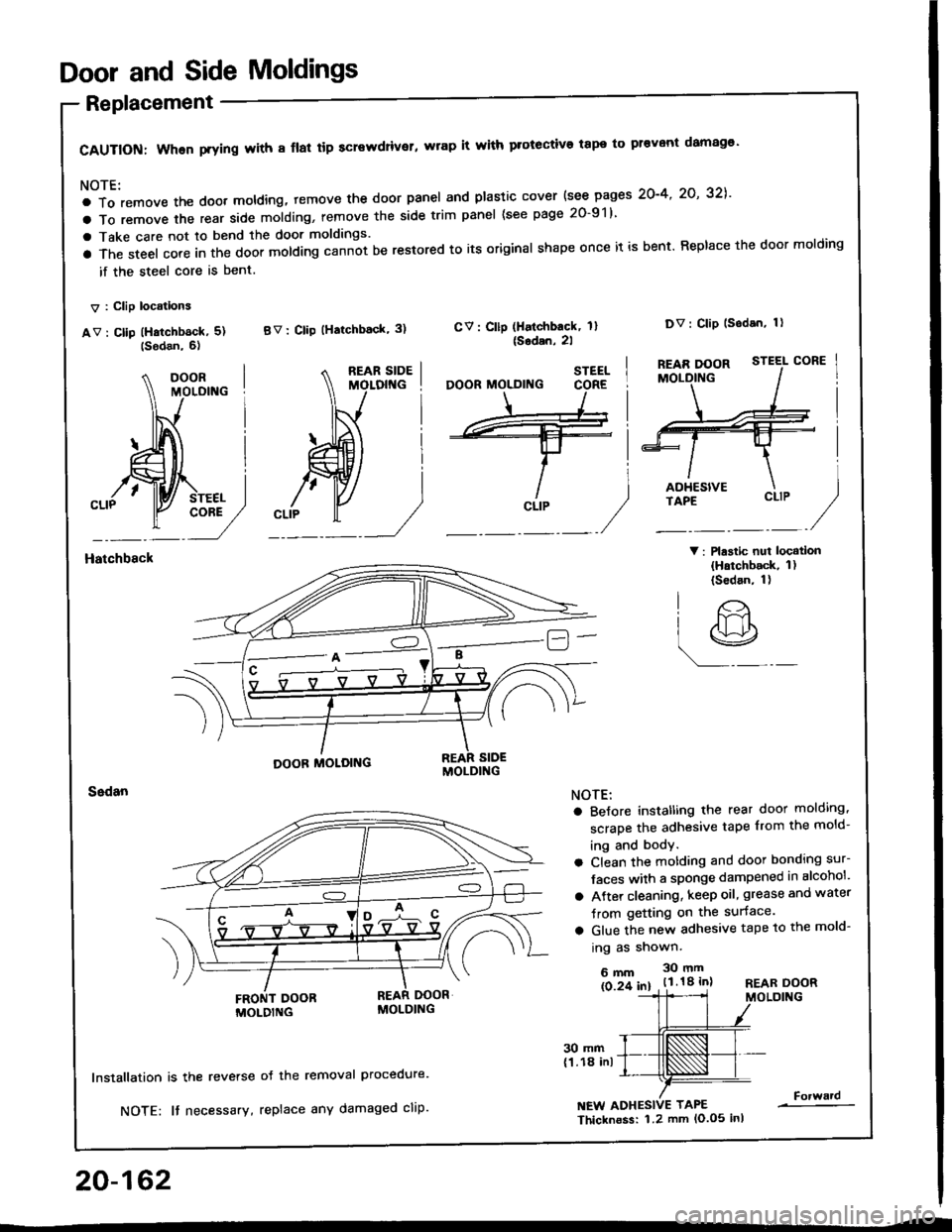
Door and Side Moldings
Replacement
CAUTION: When prying with 8 flal tip screwdriver, wrap it with protective tape to pr€vont damag€'
NOTE:
a To remove the doot moldlng, temove the door panel and plastic cover {see pages 2O-4' 2O' 32],'
a To remove the rear side molding, remove the side trim panel (see page 20-91)
a Take care not to bend the door moldings.
a The steel core in the door molding cann-ot be restored to its original shape once it is bent. Replace the door molding
if the steel core is bent.
V : Clip locations
av : cllp (Hatchb6ck, 5) BV: clip (Hatchback' 3)
V: Plastic nui locatlon(Hatchback, 1)(Sedan, 1)
CV: Cllp (Halchback, 1l{Sodan,2l
Dv: Clip lsodan, 1)
Hatchbsck
20-162
30 mm(1.18 inl
lnstallation is the reverse
NOTE: It necessary,
oJ the removal Procedure.
replace any damaged cliP.NEW ADHESIVE TAPE
Thicknoss: 1.2 mm lo.o5 inl
Forward
STEEL
CLIP
O'
lr>
r9
NOTE:
a BeJore instatling the rear door molding,
scrape the adhesive tape from the mold-
ing and body.
a Clean the motding and door bonding sur-
Jaces with a sponge dampened in alcohol'
a Atter cleaning, keep oil, grease and water
Jrom getting on the surface.
a Glue the new adhesive tape to the mold-
ing as shown.
6mm 30mm
ls 2f 61 . t.l.18 inlREAR DOORMOLDING
Page 1134 of 1413

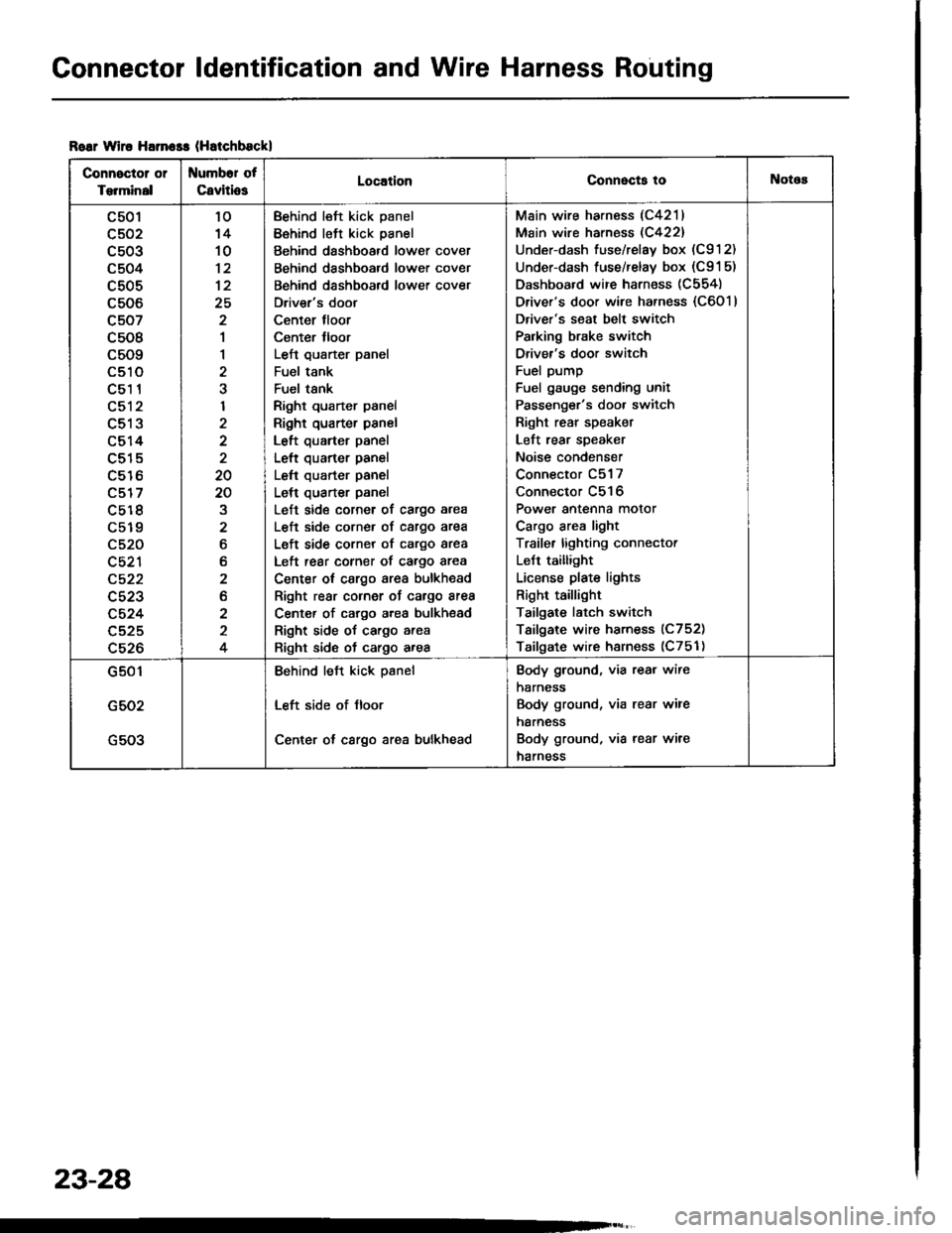
Connector ldentification and Wire Harness Routing
Roar wiro Harn$s (Hatchbsckl
Connector or
Torminal
Numbor of
CavitiosLocationConnecta tollotos
c501
c502
c503
c504
c505
c506
c507
c508
c509
LStt
c51 1
c512
c513
c514
c515
c516
c517
c5r 8
c519
c520
c521
c522
c523
c524
c525
c526
10'14
10
12
25
2
1
1
2
I
2
20
20
2
6
b
2
2
2
4
Behind left kick panel
Behind left kick panel
Behind dashboard lower cover
Behind dashboard lower cover
Behind dashboard lower cover
Driver's door
Center tloor
Center lloor
Left qusrter panel
Fuel tank
Fuel tsnk
Right quarter panel
Right quarter panel
Left quarter panel
Left quarter panel
Left quarter panel
Left quarter panel
Left side corner of cargo area
L€ft side corner of cargo area
Left side corner of cargo area
Left rear corner of cargo area
Center ot cargo area bulkhead
Right rear cornor oJ cargo area
Center of cargo area bulkhsad
Right side of cargo area
Right side of cargo area
Main wire harness (C4211
Main wire harness (C422)
Under-dash fuse/relay box (C912)
Under-dash fuse/relay box (C91 5)
Dashboard wire harness (C554)
Driver's door wire harness {C6011
Driver's seat belt switch
Palking brake switch
Driver's door switch
Fuel pump
Fuel gauge sending unit
Passenger's door switch
Right rear speaket
Left rear speaker
Noise condenser
Connector C517
Connector C516
Power antenna motor
Cargo area light
Traile. lighting connector
LeJt taillight
License plate lights
Right taillight
Tailgate latch switch
Tailgate wire harness (C752)
Tailgate wire harness (C751)
G501
G502
G503
Behind left kick psnel
Left side of Jloor
Center ot cargo area bulkhead
Body ground, via rear wire
harness
Body ground, via rear wire
harness
Body ground, via rear wire
harness
23-28
Page 1136 of 1413

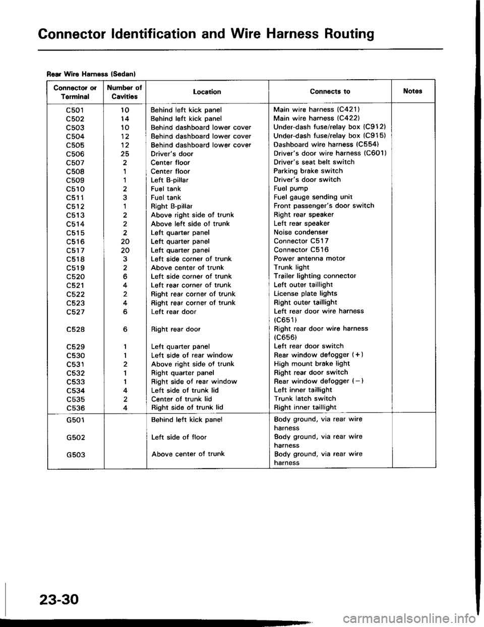
Connector ldentification and Wire Harness Routing
Rear Wire HamsEs (S6danl
Connector ol
Torminal
Number ot
Caviti6sLocaiionConnocts toNotos
c501
c503
c504
c505
c506
c507
c508
c509
c510aEt t
c512
L9 IJ
c514
c515
c516
c517
c518
c519
c520
c521
c522
c523
c527
c52A
LCZY
c530
c531
c532
c533
c534
c535
c536
6
1,|
2
1
I
4
4
10
10
12
25
'I
1
a
1
2
2
20
20
2
6
4
4
6
Behind left kick panel
Behind left kick panel
Behind dashboard lower cover
Behind dashboard lower cover
Behind dashboard lowe, cover
Driver's door
Center floor
Center floor
Left B-pillar
Fuel tank
Fuel tank
Right B'pillar
Above right side of trunk
Above left side ot trunk
Left quarter panel
Left quarter panel
Left quarter panel
Left side corner of trunk
Above center of trunk
Left side corner of trunk
Left rear corner of trunk
Right rear corner of trunk
Right rear corner of trunk
Left ,ear door
Right rear door
LeJt quarter panel
LeJt side oJ rear window
Above right side of trunk
Right quarter panel
Right side of rear window
Left side ot trunk lid
Center ot trunk lid
Right side ot trunk lid
Main wire harness (C421)
Main wire harness (C422)
Under-dash tuse/relay box {C912}
Under-dash fuse/relay box (C915)
Dashboard wire harness (C554)
Driver's door wire harness (C6O l )
Driver's seat belt switch
Parking brake switch
Driver's door switch
Fuel pump
Fuel gauge sending unil
Front passenger's door switch
Right rear speaker
Left rear speaker
Noise condenser
Connector C517
Connector C516
Power antenna motor
Trunk light
Trailer lighting conneclor
Left outer taillighr
License plate lights
Right outer taillighr
Left rear door wire harness
(c651)
Right rear door wire harness
(c656)
Lett rear door switch
Rear window delogget (+ )
High mount btake light
Right rear door switch
Rear window defogger (- )
Left inner taillight
T,unk latch switch
Right inner taillight
G501
G502
G503
Behind lett kick panel
Left side of floor
Above center of trunk
Body ground, via rear wire
narness
Body ground, via rear wire
narness
Body ground, via rear wire
narness
23-30
Page 1140 of 1413
Connector ldentification and Wire Harness Routing
Drlvar's Door Wir6 Hamors
Connectot 01
Torminal
Number of
CavitlesLocationConnocts toNotos
c601
c602
c603
c604
c605
c605
c606
c607
c608
c609
c610
c61 1
c612
25
2
4
14
I
I
10
10
o
2
I
Driver's door
Driver's door
Driver's door
Driver's door
Behind mirror panel
Driver's door
Driver's door
Driver's door
Driv€r's door
Driver's door
Driver's door
Oriver's door
Driver's door
Oriver's door wire harness (C506)
Driver's door speaker
Driver's power window motor
Power door lock control unit
Left power mirror
Left power mirror
Lett tweeter
Driver's door lock switch
Power mirror switch
Power window master switch
D.iver's door lock actuator as-
sembly
Driver's key cylinder switch
Power window master switchSedan
Hatchback
Sedan
818C1
engrne
23-34
Page 1298 of 1413
![HONDA INTEGRA 1994 4.G Workshop Manual Terminals
Connects to
\
*i,.,-terlll
FO] ANTENNA LEADA
TI!NM[IAL
A9---------+A16
Stereo Sound System
Stereo Radio/Cassette PlayerFront Speaker/Tweeter
Replacement
Front Spoakor:
1. Carefully pry out t HONDA INTEGRA 1994 4.G Workshop Manual Terminals
Connects to
\
*i,.,-terlll
FO] ANTENNA LEADA
TI!NM[IAL
A9---------+A16
Stereo Sound System
Stereo Radio/Cassette PlayerFront Speaker/Tweeter
Replacement
Front Spoakor:
1. Carefully pry out t](/manual-img/13/6067/w960_6067-1297.png)
Terminals
Connects to
\
*i,.,-terlll
FO] ANTENNA LEADA
TI!NM[IAL
A9---------+A16
Stereo Sound System
Stereo Radio/Cassette PlayerFront Speaker/Tweeter
Replacement
Front Spoakor:
1. Carefully pry out the speaker cover.
2. Remove the three screws, then disconnect the 2-P
connector Jrom the speaker, and remove the
speaker.
2.P CONNECTOR
Twootor:
1. Remove the door panel and disconnect the tweeter
2-P connector.
2. Remove the two screws, then remove the tweeter
ano covet.
r^l
It
\7
rSPEAKERCOVER
A1RED/GRNFront passenger's door speaker O
A2BLU/GRNDriver's door speaker @
A3RED/BLKLights-on signal
A4WHT/8LUConstant power {Tuning memory)
A5YEL/REDACC (Main stereo powe. supplyl
A6YEL/GRNRadio switched power (To antenna)
A7BLU/YELLeft rear speaker O
A8RED/YELRight rear speaker @
A9BRN/BLKFront passenger's door speaker O
A10GRY/BLKDriver's door speaker O
A lnot used)
412(not used)
A13(not usedl
A14BLKGround (G551)
Al5GRY/WHTLeft rear speaker O
A16BRNAA/HTRight rear speaker e
23-192
IFrIFit
Page 1324 of 1413
Power Mirrors
Switch Test
Remove the driver's door panel (see section 2O).
Check tor continuitv between the terminals in each
switch position according to the table.
Mirror Switch
rermrnal
Position \J
R
OFFG"
UP
-o
o--<>-
DOWN
-o
o--o
LEFTo-
-o
RIGHT
-o
o-
OFFo--o
UP
o--(J_
DOWN
-o
G--o
tEFT
-o
-o
RIGHTG-
P-o
23-214
aaaaaaaa
A-------+J