Page 1181 of 1413
Circuit Diagram (A/T)
G?{raoswncH
6i\-{€ o+
\_v I
IBl-torvHT
II
I,(h A/I GEAR
g, ffi.:11?[:#ir11,",,
I
IBI.K/BED
UI{DER -HOOD FUSE/NEUY BOX
N,0.41 {l00Al Io.39160 t
Page 1194 of 1413
lgnition System
Circuit Diagram
CKP: Cr6nk.halt posilioo sonsorCYP| Cylindor position s€nsor
TOC/CKP/CYP SENSOR
-_r_1=__E
-J---L--L--Lr
ORN
U'+++
UNOER- HOOO FUSE/RELAY BOX
ECM
V
I
YEUGNiI
tG tTtoN c0NTROl-MoDUr.r (cMl
/ H8s built - in \I OOrsO I
23-88
Page 1205 of 1413
Circuit Diagram
UI,IDER - HOOD FUS€/REI.AY 8OX
*1 :USA+2 llo.24 ll SAl: 81881 .mintlo.24 {2041: 818C | .niin6
. NTEGRATEDCOMTNOL UMT. aBs coilTRor- uNn
VI
I
ECM
V
I
I
UNDER_OASHFUSE/REIAY 8OX
oiotG401
No.4t 11004) /a ilo.39l50Al
Fr€|'l) wNort'lc
AI.TERNATOR
23-99
Page 1216 of 1413
ul{o€R - DAstlGIINONSWITCH FUSC/RELAYBOX
Circuit Diagram (Without A/Cl
UI{OER - HOOD FUS€/REI.AY BOX
6r F'rrr^'l.{ ots YEt {<\o*r
\-Y -l
ECM
V
Gtr{
l,*^,
($fffiHil'r"n.''
I
t?i'r?Tdf.ol
I
ffi,"'l
IBtl(
I
I:
G10l
Fan Controls
23-110
No.4l {lmA, No.39l50Al
FIIF.-
Page 1217 of 1413
G FION SWIICH
No.41 l100Al No.39l50At
RAOIATORFANREI.AY
Gircuit Diagram (With A/Cl
UNOER - HOOO FUSE/REIAY BOX
,5
GRt{
| ,*n,n,,z*r CoOtAt{TqU llffffarunErEcrr
I
t?i'i."1",i:"ol
Imonron IFAN IMOTOR
I
IBI-K
I
I:
G10l
23-111
Page 1222 of 1413
Gauge Assembly
Gircuit Diagram
r3 [o.24 ll5 ): 81E81 dttr10,24120 ):B1&1.mirulocn-D sHRISC/RELAY &X
Tw'lcu I
+ 3r,4ts. rt_gstr
Il{l(
IA:6t0l
sastNtT
T
FUSE
snstxocAloRUGTIT[fffi"vv
N'ElGAI.EEsExDr6 ulllT
.lsffiisl{,MT
VI- r Gin&no
".lJrlI C,afi/ilD
ilrlrl
in- | ()" | | snrxt. r I Rlp
i |ffi.rlItrr
rl
iAt:
r6ii G30r
GMVn!O
#nI RUNIiITG II uGfiTs \
l8flfl*' ;
ht0/Git{
IGn[/Ft0
6mii'
I-
a{G|l|€c@lat{TIl$EiA'l iltErcTtSAdTGtxt
23-116
Page 1232 of 1413

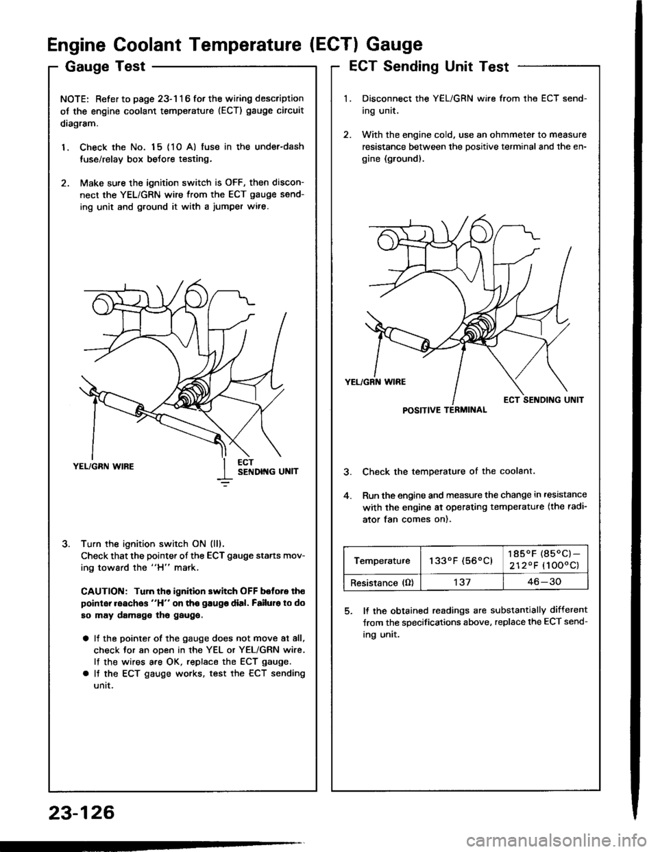
GaugeTest
NOTE: Refer to page 23-116 fot the wiring description
oJ the engine coolant temperature (ECT) gauge circuit
diagram.
1. Check the No. 15 (10 A) fuse in the under-dash
tuse/relay box before testing.
2. Make sure the ignition switch is OFF, then discon-
nect the YEL/GRN wire from the ECT gauge send-
ing unit and g.ound it with a jumper wire.
Turn the ignition switch ON (lll.
Check that the pointer of the ECT gauge starts mov-
ing toward the "H" mark,
CAUTION: Tuln th6 ignition switch OFF botore th€
point reaches "H" on tho gaugo dial. Failuro to do
so may damago tho gaugo.
a It the pointer of the gauge does not move at all,
check Jor an oDen in rhe YEL or YEL/GRN wire.
lf the wires are OK, replsce the ECT gauge.
a It the ECT gauge works, test the ECT sending
untt.
J.
Engine Coolant Temperature (ECTI Gauge
ECT Sending Unit Test
Disconnect the YEL/GRN wire from the ECT send-
ing unit.
With the engine cold, use an ohmmeter to measure
resistance between the positive terminal and the en-
gine (ground).
Check the temperature of the coolant.
Run the engine and measure the change in ,esistance
with the engine ai operating temperatu.e {the radi-
ator tan comes on).
5. ll the obtained readings are substantially different
Jrom the specifications above, replace the ECT send-
ing unit.
23-126
POSITIVE TERMINAL
Temperatu.e1330F (560C)185.F (850C)-
2120F (1000c)
Resistance (O)'t3746-30
Page 1236 of 1413
Maintenance Reminder System
Circuit Diagram
23-130
UNDER-HOOD FUSE/REIAY 8OX
MAINIET,IAT,ICE REMINOER UiIIT