Page 1239 of 1413
UNOER_HOOD FUSE / REI.AY 8OX
Circuit Diagram
IGNITIONswrTcHUNOER-OASHFUSSREI-AY 8OX
No.19ll0A)FUSE
TMI{SMrSSr0r,lc0IJTRori.IODULEITCMI
fitMritc-;-CANCEL lgll
tlYELTWHT GRN/8L|(
D4
II._l
TRANSMISSIONMODU|.! [TCM}
t
INTERLOCKcoMtRotUNJ]_
IGRT'IMHTo*nn,o_yTT
pr{x/cR1 -J
IGR €|-U -l
GRiITYEt
LT GNNiW{T
No.19 {lFUSE
V
I
I
DASH I-IGHTSBRIGHTNESSCONTROI.IERG2o lG401
I
G201G40t
/-?t ftrt*lwHT/BLX +wHT+ CH- Bl.x/Y€t -+<.\-o+!
y "l
IYEL
lln tho gtugo 8ls€mbvl
AN GEAR POSITION INDICATOR DIMMING CIRCUIT
A/T GEANPOStTt0NcoNsot-ELIGHT0.4w)
M GEARPosrTroN swncH
23-133
Page 1246 of 1413
lnterlock System
Circuit Diagram
NOTE: Different wires with the same color have been given a number suffix to distinguish them (tor examplg,
GRNMHT 1 and GRNMHT 2 are not the same).
W}IT/BLK +WHT
Y I if,f,trfi
I i
^'v"'
IIN/vt,H] ,
I
l......................_GRNA,t/r{rz1
/r S'ftiei
f lJlT,ll*n""n,
UNOER -HOOD FUSE/REi.AY BOX
N0.41 (1OCA) No.39 l50A)
THROTTLEPOSITION ITPISENSOR
WHT/GRN
23-140
Page 1250 of 1413
Integrated Control Unit
Circuit Diagram
D.3c ptlon
An integrat€d control unit, located in the left kick panel, integratss the functions of tho keyin/seat beh r6mind€r, sido
markar light {lasher, wiper/washer, lights-on r6minder, rear window dsfogger timer, brak€ system light bulb check, and
enging oil pressure indicator flasher circuitE,
NOTE: Difforent wires with the same color have be6n given a numbor suffix to distinguish them (for Example,
GRN/RED1 and GRN/RED'� are not the same).
WNOSHIELD WIPER/WASHER SWITCH
IMT OFFiINT
I
II
IIIIIIIIIIII
YEUEE
rl
t
P
UNOER - DASH FUS€/RETAY BOX
r NTEGRATED COI{TROI UNIT
t-0wErGrilE 0|lPRESSI'REINDICATORLIGI{T
WINDSHIELOWIPERAVASHERswtTcH
tr-/
IBLK/GRN BI
WINDSHIELOWIPERMOTOR{Asl
VOLTAGEREGULATOR{ln ahamator,
UNOER- HOOD FUSE/RELAY 8OX
I
r3
r8relit;rBt5I
23-144
lr ) : With combinod washef-wip€r oporation
Page 1256 of 1413

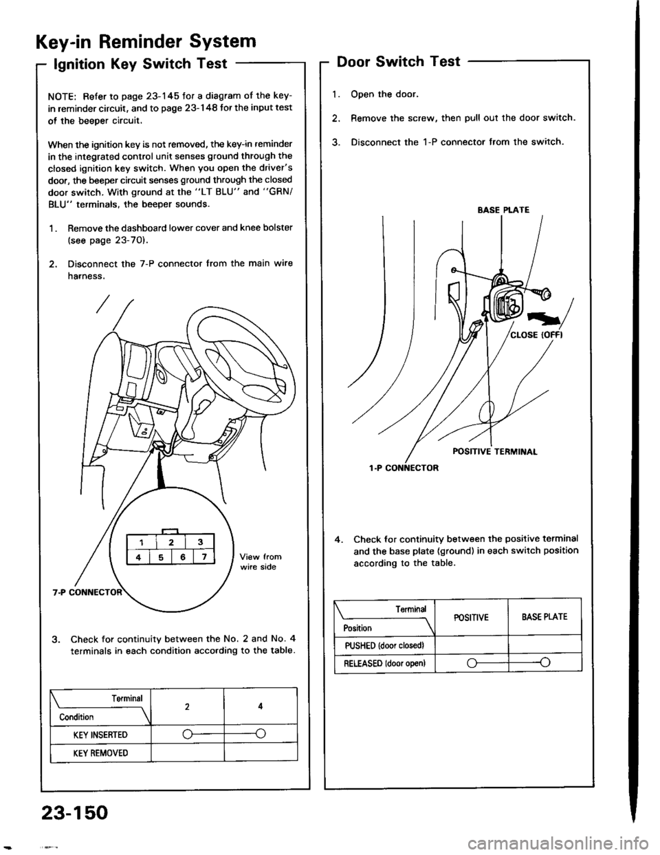
Key-in Reminder System
lgnition Key Switch Test
NOTE: Refer to page 23-145fot a diagram of the key-
in leminder circuit, and to page 23-148 Jor the input test
ol the beeper circuit.
When the ignition key is not removed, the key-in reminder
in the integrated control unit senses ground through the
closed ignition key switch. When you open the driver's
door, the beeper circuit senses ground through the closed
door switch, With ground at the "LT BLU" and "GRN/
BLU" terminals, the beeper sounds.
1 . Remove the dashboard lower cover and knee bolster
(see page 23-70).
2. Disconnect the 7-P connector from the main wire
harness.
Check for continuity between the No. 2 and No. 4
terminals in each condition acco.ding to the table.
l.
Door Switch Test
Open the door.
Remove the screw, then pull out the door switch.
Disconnect the 1-P connector from the switch.
4. Check lor continuity between the positive terminal
and the base plate (ground) in each switch position
according to the table.
BASE PLATE
Position
TerminalPOSITIVEBASE PLATE
PUSHED {door closedl
RELEASED ldoor o!en)oo
Terminal
Condition
4
KEY INSERTED--o
KEY REMOVED
23-150
Page 1257 of 1413

Engine Oil Pressure
Indicator System
Description
NOTE: Reter to page 23-144 tor the circuit diagram otthe engine oil pressure indicator flasher, snd to page
23-148 lor the input test of the flasher circuit.
The low engine oil pressure indicator tight works in twoways. lt will flash continuously following a momentaryloss of oil pressure, or it will go on and stay on with acomplete loss of oil pressure.
When the engine first starts, before oil Dressure risesabove 29.4 kP8 10.3 kgf/cmr, 4.3 psi), current flowsthrough the low engine oil pressure indicator light andthe oil pressure switch to ground. This tests the circuit.
Wilh the engine running, voltage is applied ro the ftash-er circuit of the integrated control unit. With normal oilpressure, the oil pressure switch is open and the low en-gine oil pressure indicator light does not operate. lf theoil pressure switch closes momentarily (more than O.5secondsl, but then opens again, terminal "yEL/RED,'will
sense ground through the switch. The integrated con-trol unit willthen provide and remove ground for th€ lowengine oil pressure indicator light through terminal"YEL/RED". The light will flash on and olf until the igni-tion switch is turned to "OFF".
lf engine oil pressure falls below 29.4 kPa (O.3 kgJ/cmr,4.3 psi) and does not increase, the oil pressure switchwillstsy closed. The low engine oilpressure indicator lightwill go on and stav on.
NOTE; Refer to page 23-122lot the engine oil pressure
switch test.
Lights-on Reminder
System
Description
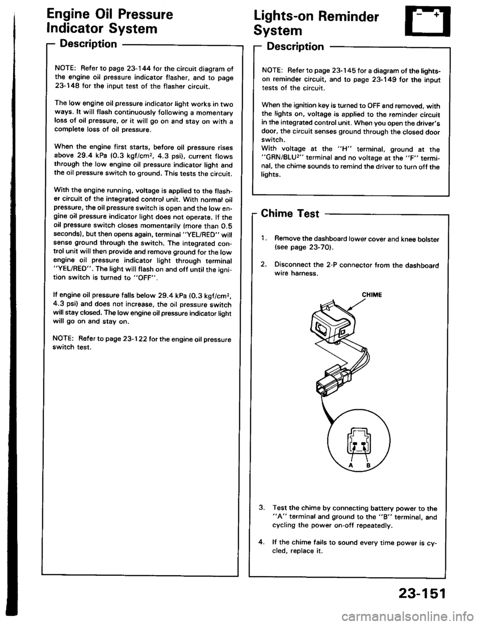
Chime Test
Remove the dashboard lower cover and knee bolster
{see page 23-70).
Disconnect the 2-P connector t.om the dashboardwire hamess.
Test the chime by connecting battery power to the"A" te.minal and ground to the "B" terminal, andcycling the power on-off repestedly.
lf the chime fails to sound every time power is cy-cled, reDlace it.
NOTE: Refer to page 23-145 tor a diagram of the lights-
on reminder circuit, and to page 23-149 for the input
tests of the circuit.
When the ignition key is turned to OFF 8nd removed. withthe lights on, voltage is apptied to the reminder circuitin the integrat€d control unit. When you open the driver,sdoor, the circuit senses ground through the closed doorswitch.
With voltage at the "H" terminal, ground at the"GRN/BLU2" terminal and no voltage at the ,,F,' termi-nal, the chime sounds to remind the driver to turn oJf thelights.
CHIME
23-151
Page 1260 of 1413
Lighting System
Circuit Diagram (USAI
UNOER - HOOD RJSE/NELAY 8OX
-r lo| ,-. otFDIMMER I'I
No.2l|l0A]iil;
)
ttNo.lo '1 No,22 ''t No.gtloAr (0oA) (floAr
IT
HEADLIGHTRIGHTHEAOUGHT
HIGH EEAMINOICATORLIGHTfi.4W)@il,", @f,*,6il* 6p*
. PAR(II{G UGHI. TAILUGI{TS. UCENSE PI.ATE
UtrloER - D SHRJSE/RELAYsox
REO/GNN
8LK
I
G20lG401
DASH UGI{TS88rGr{T ESSCONTrcUTRDASH UGHTSPAR(II{C UGHTSTAItUGt{TSUCENSE PI.ATEUGHTS
8tK
G301G20'�|G40l
23-154
Page 1261 of 1413
Gircuit Diagram (Canadal
BATTERY
G"*
UNOER_HOOD FUSEiRETAY 8OX
coMBrNAtor{ rcHrswnc
-il w
| '.=r" I
ll'L I I
I I *o\." l-'li' ;- ;j
I LI
"- r.r-,9 "orr
I
d "
L
RED/BLU REO/}VHT RED,ll
I UNDEN-DASH II FUSEiIEI,AY 8OX I
tl
L-J
t'GRN
/d\BATtG2\9-l
rGNrTrot{swITcH
No.2lfl0A)\I
No.l9|l04]Jm.tr (
t10A) ttt
I
No.l6{7.54}
tl
i,"#
llrrff li'rrt,
RED/GRtIIBLU REOr'TVHTINED/B
V
WHTTYEL
. DASH LGHTS BRIGHTNESSCOI{TROLLER. DASH I-IGHTS. PARKING I-GHIS. TAII,LIGHTS. UCENSE N"AT€ LIGI{TS
I a-rneonru jllA/Vr l"o I f# wxrintoRED/GRI{ +\{H I
DAYTIME RUNNINGUGI{TS RESISTOR
IRED/GRN
Hr I r-01651,1/) | l55W)HIt85W)LOt55Wl
HIGH BEAMINOICATORUGHTfl.4W
I
RIGHTHEADLIGHTPARKIIIGBRAKEsw{TcH
23-155
Page 1276 of 1413
UNDER. HOOD FUSE/REIAY 8OX
Dash Lights Brightness Gontrol
Circuit Diagram
COMBII{ATIONLIGI{T SWTTCH
wnr-@- neorenn
REO/BLK
. GATJGE UGHTS. CruEE COITNOL DIMMING CIRCUTT. A/T GEAR POSMON N(ICATORDIMMII{G CIRCUIT' HAZAnD WARi{|NG S:WltCH LIG}fr. REAR WINOOW OEFOGGER SiWTTCH UGHT. CFUISE COMTROT MAIN S,IVITCH UGHT. A,IT GEAN POSITION CONSO|.! UGHT. HEATER COMTNOL PANEL UGHTS
TR€D
BI.K
G201G40t
23-170
UNDER- DASHFUSE/NETAY 8OX
IEF