Page 327 of 1413

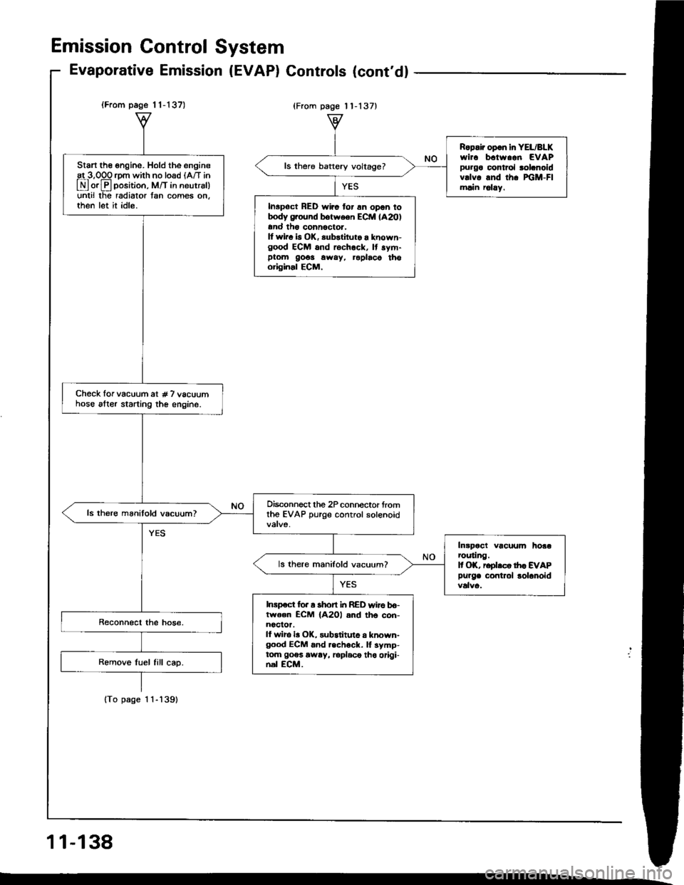
(From page 1 1-137)
lTo page 1 1-'l39)
Start the engine. Hold the engineat 3,OOO rom with no load lA/T in
E orE position, M/T in neutrsl)unlil lhe radiator tan comes on.then let it idle.
Check lor vacuum at # 7 vacuumhose alter starting the engine.
Oisconnect the 2P connoctor fromthe EVAP purge control solenoid
Intpoct vacuum hoaarcuting.It OK, reolrco tr|c EVAP
Purge contlol lolanoid
ls there manifold vacuum?
Inrpoct for a short i|t RED wire bo-lwoen ECM {A2Ol and th6 con-noclor.ll wiro la OK, substituto a known-good ECM 6nd .echock. lf symp-tom goes away, loplace tho origi-nal ECM.
Ropair opon in YEL/BLKwirc b.tw..n EVAPpurgo control rolanoidvrlvo and th. xiM-Flmlin r6lay.
ls there baftery voltage?
Inspoct RED wirc for 6n opon totrody g.ound botween ECM lA20)and th6 conn6ctor.It wir. b OK, substiluto a known-good ECM and rochock, It sym-ptom 9o6s away, roplaco thooriginal ECM,
Emission Gontrol System
Evaporative Emission (EVAP) Gontrols (cont'd)
{From page 11-137}
11-138
Page 332 of 1413
Special Tools
Ref. No, I Tool NumberDescriptionOty Page Reference
o/^
ri)
@
@
OTJAF_PM7011A
OTLAB PVOO1 OO or
o7 924-PD20003
07NAF-PR30100
07746-0010100
07749-OO10000
07936-3710100
Clutch Alignment Disc
Ring Gear Holder
Clutch Alignment Shaft
Attachment, 32 x 35 mm
Driver
Handle
'I
1
I
1
I
I
12,7
12-1, 8, 9, 10
12-7 , 8, 10
12-10
12-10
12-1 , 8, 10
I
12-2
Page 333 of 1413

lllustrated Index
NOTE:
a Whenever the transmission is removed, clean and grease the release bearing sliding sudace.
a It the pans marked r are removed. the clutch hydraulic system must be bled (see page 12-6).
a Inspect the hoses lor damage, leaks, interterence, and twisting.
*RESERVOIR
HOSEASSISI SPRING
PEDAL PIN
CLUTCH PEDALAdjustment,page 12-4
15 N.m 11.5 kgl.m,11 tbt.ftl
6 x 1,0 mm9.8 N.m ll.0 ksf.m, 7 lbf.tt)
FLYWHEELInspection. page 12-9Replacement, page 12-9
TCLUTCH MASTER CYLINDERRemoval/lnstallation, page 1 2-5
19 N.m ll.9 kgt.m,14 lbf.ftl
.CLUTCH PIPE
15 N.m {1.5 kgl.m,1 1 rbf.ft)
ICLUTCH PIPE
JOtt{T
8 x 1.25 mm25 N.m (2.6 kgl.m,19 lbt.ttl
RELEASE BEARINGRomovaf /lnspection, page 1 2-1 1lnstaffation, page 1 2- 1 2
TRANSMISSIONRomoval. see
CLUTCH DISCRemoval/lnspection. page'1 2-8Installation, page 12-10
8 x 1.25 mm22 N.m (2.2 kgf.m.16 lbl.rr)
section 1312 x 1.0 mm103 N.m llO.5 kgt.m,76 rbf.ftl
PRESSURE PLATERemoval/lnspection. page 1 2-7Installation, page 12,10
TSLAVE CYLINDERRemovaf /lnstallation. page 1 2-632 N.m {3.3 kgf'm,24 tbf.ftl
15 N. m {1.5 kgf.m,'| I tbf.ftl
COTTERBeplace.
I
NInl
9t
v-_fl
ICLUTCH
12-3
Page 334 of 1413

Adjustment
NOTE:
a To check the clutch interlock switch and clutch
switch, see seclion 23.
a The clutch is selt-adjusting to compensate for wear.
CAUTION: It there is no clearanco between the mastel
cylinder piston and push lod. the releaso boaring is held
againsl the diaphragm spring, which can result in clutch
slippage 01 othel clutch problems.
Loosen locknut A, and back otf the clutch switch
{or adjusting bolt) until it no longer touches the clutch
pedal.
Loosen locknut C, and turn the push rod in or out
to get the specified stroke (@) and height (O) at the
clutch pedal.
Tighten locknut C.
Turn the clutch switch (or adjusting bolt) until it con-
tacts the clutch pedal.
Turn the clutch switch (or adjusting bolt) in 3/4 to
1 full turn further.
Tighten locknur A.
7. Loosen locknut B and the clutch interlock switch.
8. Measure the clearance between the tloor board and
clutch pedal with the clutch pedal tully depressed.
9. Release the clutch pedal 15-20 mm {O.59-O.79
in) from the fully depressed position and hold it there.
Adiust the position of the clutch interlock switch so
that the engine will start with the clutch pedal in this
oosition.
1 0. Turn clutch interlock switch 3/4 to 1 tull turn funher.
11. Tighten locknut B.
LOCKNUT B9.8 N.m (1.0 kgf.m, 7 lbf.ftl
CLUTCH INTERLOCKswtrcH
6.
1.
2.
ASSIST SPRING
-6ll
LOCKNUT Cl3 N.m l'l.3 kgf.m, 9
CLUTCH SWITCH{or AOJUSTING BOLTI
LOCKNUT A9.8 {N.ml (1.0 kgl.m, 7 lbt.ftl
(STROKE at PEDALI: 130-140 mm 15.12-5.51 in){TOTAL CLUTCH PEDAL FREE PLAY): 12-21 mm 10.47-0.83 inl including tho p.dal play I -lO mm 10.04-0.39 inl{CLUTCH PEDAL HEIGHTI: 164 mm (6.46 in} to tho lloot{CLUTCH PEDAL DISENGAGEMENT HEIGHTI: 83 mm 13.27 inl minimum to tho lloo.
PUSH ROD
CLUTCH MASTER CYLINDER
Clutch Pedalctutch Pedat I
[-],ll'"-"" f
| :;i:'":fff*tr#:?iff:".,*::,::". | .#::J:::
sb''�'�'""
| |
| "orr,O", It there is no clearanco between the master | ,. aoo""n locknut B and the clutch intertoct switcl. | |cylinder piston and push lod. the releaso boaring is held | | Iagainst the diaphragm spring, which can result in clutch | 8. Measure tne clearance between the floor board and I Islippage 01 othel clutch problems.
I
clutch pedal with the clutch pedal tully deeressed.
I I1. Loosen locknut A, and back otf the clutch switch | 9. Release the clutch pedal 15-2O mm (O.59-O.79 I I
{or adiusting boltl until it no longer touches the clutch I int trom ttre fully depressed position and hold it there. I I
, ::":"" rocknut c, and rurn the push rod in or out | iliiiliffi:l1l:J"'1"-:H"l:tJ:i"i#fT: I I
. il*:*j':"'-(@)andheisht(olatthe
|
,:.;:,nterrockswitch3/4torrurrturnturtner.
I tf
,
::
***r**''
.,".,u"**;
|
'-"'"'';*1,,0*.,.-,.,*,
I I
Page 335 of 1413
Clutch Master Cylinder
Removal/lnstallation
CAUTION:
a Do not sgill b.ake lluid on the car; it may damags the
painl; it biake fluid does contact tha paint. wash it
otf immediately with water.
a Plug lhe end ot the clutch pips and r€servoil hose with
a shop towel to prsvent blake fluid ttom coming out.
1. Remove the brake fluid from the clutch master
cylinde. reservoir with a syringe.
2. Disconnect the clutch oioe and reservoir hose from
the clutch master cvlinder.
CLUICH PIPE15 N'm {1.5 kgl.m,1 1 tbf.ftl
CLUTCHMASTERCYLINDER
Pry out the cotter pin. and pull the pedal pin out ot
the yoke. Remove the nuts.
NUTS13 N.m {1.3 kgf.m,9 lbt.frl
Remove the clutch master cylinder.
NOTE: Do not spill brake fluid on the
cylinder damper.
OAMPERCLUMAIcYL
Install the clutch master cylinder in
der of removal.
NOTE: Bleed the clutch hydraulic s\
12-61.
clutch master
CLUTCHMASTERCYLINDER
!l rn Ine reverse or-
c system (see page
12-5
Page 337 of 1413

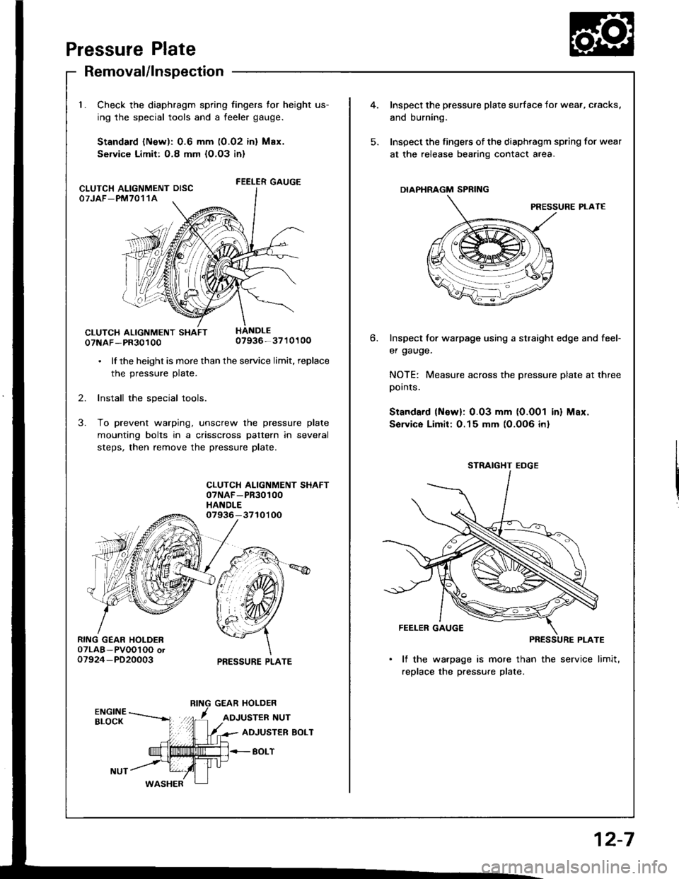
Pressure Plate
RING GEAR HOLDER07LAB-PVOOl OO or07924-PD20003
Removal/lnspection
Check the diaphragm spring fingers for height us-
ing the special tools and a feeler gauge.
Standard lNew): 0.6 mm (0.02 inl Max.
Service Limit: O.8 mm {O.O3 in}
FEELER GAUGE
07NAF-PR3010007936-3710100
. lf the height is more than the service limit, replace
the pressure plate.
2. Install the special tools.
3. To prevent warping, unscrew the pressure plate
mounting bolts in a crisscross pattern in several
steps, then remove the pressure plate.
CLUTCH ALIGNMENT SHAFT07NAF-PR30100HANDLE07936-3710'l OO
PRESSURE PLATE
CLUTCH ALIGNMENT OISCOTJAF_PM7011A
4.Inspect the pressure plate surface
and burning.
Inspect the fingers of the diaphrag
at the release bearing contact ar
DIAPHRAGM SPRING
Inspect for warpage using a stru
er gauge.
NOTE: Measure across the prer
pornls.
Standard (Newl: 0.03 mm (0.0
Sorvice Limit:0.15 mm (0.0O6
STRAIGHT EOGE
FEELER GAUGE
PI
lf the warpage is more than
replace the pressure plate.
6.
I surface for wear, cracks,
diaphragm spring for wear
nracr area.
PRESSURE PLAT€
straight edge and feef
pressure plate at three
0.001 in) Max.
)O6 inl
12-7
Page 341 of 1413
spection
release fork boot trom the clutch4. Torque the mounting bolts in a crisscross pattern as
shown. Tighten the bolts in several steps to prevent
warping the diaphragm spring.
8 x 1.25 mm25 N.m 12.6 kgt'm,19 tbt.ftl
2. Remove the release tork trom the clutch housing by
squeezing the release fork set spring with pliers. Re-
move the release bearing.
Check the release bearing for play by spinning it by
hand.
CAUTION: The release boaring i6 packed with
grease. Do not wash it in solvent.
Remove the special tools.
Recheck the diaphragm spring fingers tor height (see
page 12-7]..
Release Bearing
Removal/ln
1. Remove the
housing.
CLUTCH HOUSING
RELEASE FORK
-24/--2,t'.2424?'
IJ
l{ there is excessive plaY, rep)ace the rdease\Ear-
ing with a new one.
,F=:=
Page 345 of 1413

- Transmission Oil
NOTE: Check the oil with the engine OFF, and the car on
level ground.
1. Remove the oil filler plug, then check the level and
Maintenance
condition of the oil.
OIL FILLER PLUG44 N.m lia.5 kgf.m,
ORAIN PLUG$ N.m 14.0 kgf.m.29 lbf.fr)
33 tbtftlProper Level
2. The oil level must be up to the filler hole. lf it is
below the hole. add oil until it runs out, then rein-
stall rhe oil filler plug.
3. lf the transmission oil is dirty, remove the drain
plug and drain the oil.
4. Reinstall the drain plug with a new washer, and
refillthe transmission oil to the proper level.
NOTE: The drain plug washer should be replaced at
every oil change.
5 Reinstall the oil filler plug with a new washer.
OilCapacity
2.2 ( ''2.3 US.qt,1.9 lmp.qt) at oil chang€.
2-3 I l2.1Us.ql,2.0lmp.qtl at oyerhaul.
Use only SAE 10 w - 30 or '10 W - 40, API Service
SF or SG grade.
OIL FILLER PLUGa4 N.m l{.5 kgf.m, 33 lbf.ftl
Back-up Light Switch
Replacement
NOTE: To check the back-up light switch,
1. Disconnect the connector, then rem(
light switch connector trom the conn
2. Remove the back-up light switch.
BACX-UP LIGHT SWITCH25 N.m 12.5 kg[.m, 18 lbf.ftl
lnstall the new washer and the back-
Check the transmission oil level (see
Replace.
/itch, see section 23.
remove the back-up
]onnector clamp.
-up light switch.
) page 13-3).
Replace.
13-3