Page 1369 of 1413

l.
2.
1.
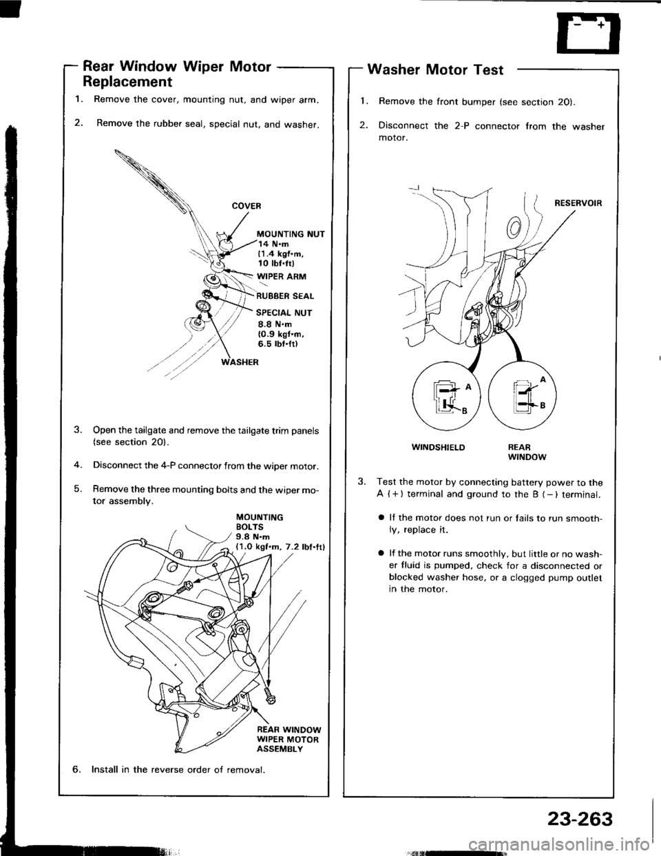
Rear Window Wiper Motor
Replacement
Remove the cover, mounting nut, and wiper arm.
Remove the rubber seal, special nut, and washer.
MOUNTING NUT
Washer Motor Test
Remove the front bumper (see section 20).
Disconnect the 2-P connector lrom the washer
motor.
RESERVOIR
WINDSHIELD
14 N.m11.4 kgf.m,10 tbt.trl
WIPER ARM
RUBBER SEAL
SPECIAL NUT
8.8 N.m{0.9 kgt'n,6.5 rbt.fr)
MOUNTINGBOLTS9.8 N.m(1.O kgf.m, 7.2 lbf.ttl
-4
)
Open the tailgate and remove the tailgate trim panels(see section 20).
Disconnect the 4-P connector from the wiper motor.
Remove the three mounting bolts and the wiper mo-
tor assembly.
REARwrNDow
Test the motor by connecting battery power to the
A ( + ) terminal and ground to the B (- ) terminal.
a ll the motor does not run or fails to run smooth-
ly, replace it.
a lf the motor runs smoothly, but little or no wash-
er fluid is pumped. check for a disconnected orblocked washer hose, or a clogged pump outlet
in the motor.
6, Install in the reverse order o{ removal.
23-263
Page 1370 of 1413
Wipers/Washers
Washer Replacement
1.
5.
6.
Bemove the Jront bumper (see section 2Ol.
Remove the left lront inner fender.
Disconnect the 2-P connector and hose from the
washer motor.
Remove the three mounting bohs and the washer
reservorr.
Remove the washer motor from the reservoir.
Remove the windshield wiper arms and air scoop
(see page 23-261). Then remove the washer noz-
zles and hoses.
lnstall in the reverse order of removal.
NOTE:
a Take care not to pinch the hoses during instal-
lation.
a Install the clips tirmly.
a After installing, adjust the aim of the washer
nozztes.
7.
REARwtt{DowWASHERt{ozzLEWINDSHIELDWASHERNOZZLE
n
V..,.,,@
l(H
n
MOUNTINGBOLTS9.8 N.m{1.O kgf.m, 7.2 lbf.ftl
23-264
Page 1378 of 1413
Front Pas3enger's Side:
. Remove the glove box damper (see section 20), and
then remove the glove box.
. Disconnect the 3-P connector between the front oas-
senger's airbag and the SRS main harness, then con-
nect the short connector (RED) to the airbag side of
the connector.
SHORT CONNECTOR(REDI
SRS MAIN HARNESS
b,
Disconnecting the SRS Connector at the
Under-dash Fuse/relay Box:
CAUTION: Avoid br.aking the connoctor; it's doubte-
locksd.
1. First lift the connector lid with a thin screwdriver,
then press the connector tab down and pull the con-neclor out.
CONNECTORt_tD
To reinstall the connector. push it into position untilit clicks, then close its lid.
23-273
Page 1381 of 1413

Supplemental Restraint System (SRSI
Troubleshooting
Self-diagnosis Function
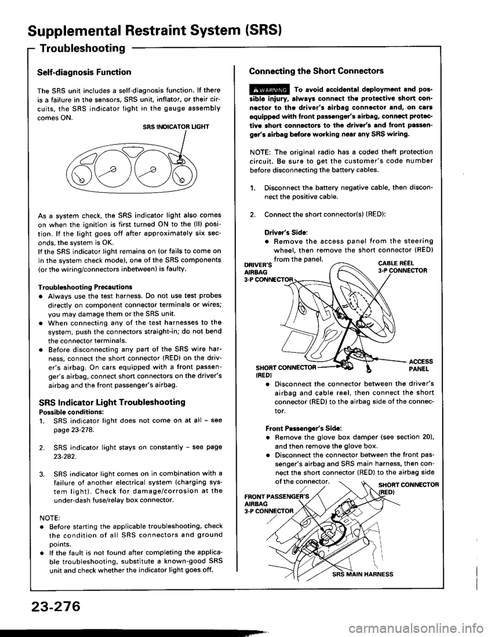
The SRS unit includes a self-diagnosis function. lf there
is a failure in the sensors. SRS unit, inflator, or their cir-
cuits, the SRS indicator light in the gauge sssembly
comes ON.
As a system check, the SRS indicator light also comes
on when the ignition is first turned ON to the (ll) posi-
tion. lf the light goes off after approximately six sec-
onds, the system is OK.
lf the SRS indicator lighr remains on (or fails to come on
in the system check mode), one of the SRS components
(or the wiring/connectors inbetween) is laulty
Troubleshooting Precautions
a Always use the test harness. Do not use test probes
directly on component connector terminals or wires;
you may damage them or the SRS unit.
a When connecting any of the test harnesses to the
system, push the connectors straight-in; do not bend
the connector terminals,
. Before disconnecting any part of the SRS wire har-
ness, connect the shon connector (RED) on the driv-
er's airbag. On cars equipped with a front passen-
ger's airbag, connect short connectors on the driver's
airbag and the front passenger's airbag.
SRS Indicator Light Troubleshooting
Possiblo conditions:
1. SRS indicator light does not come on at all - see
page 23-278.
2. SRS indicator light stays on constantly - see page
23-242.
3. SRS indicator light comes on in combination with a
failure of another electrical system (charging sys-
tem light). Check for damage/corrosion at the
under-dash tuse/relay box connector.
NOTE:
. Before starting the applicable troubleshooting. check
the condition of all SRS connectors and ground
points.
. lf the fault is not found after completing the applica-
ble troubleshooting, substitute a known-good SRS
unit and check whether the indicator light goes off.
23-276
MAIN HARNESS
Connecting the Short Connectors
@ To avoid.ccidental doploymont and pos.
siblo iniury. alway3 connect ths protoctive short con.
noctor to tha driver's airbag connectot and, on caf!
equippod with front passongor's airbag, conncqt Prolac-
tivs ghort connoctors to the d.ivsr's and tront passsn-
gar's airbag before working nsai any SRS wiring.
NOTE: The original radio has a coded theft protection
circuit. Be sure to get the customer's code number
before disconnecting the battery cables,
Disconnect the battery negative cable, then discon-
nect the oositive cable.
Connect the short connector(s) (RED):
Drivsr's Sido:
. Romove the accoss panel trom the steering
wheel, then remove the shon connector (BED)
1.
2.
from the panel.DRIVER'SAIRBAG
CABLE R€EL
3-P
ACCESSPANELSHONT CONNESTOR(REDI
. Disconnect the connector between the driver's
airbag and cable reel, then connect the short
connector {RED} to the airbag side of the connec-
tor.
Front Pas€ngo/s Sido:
. Remove the glove box damper (see section 20),
and then remove the glove box.
. Disconnect the connector between the front pas-
senger's airbag and SRS main harness, then con-
nect the short connector (RED) to the airbag side
of the connector,SHORT CONNECTOR
Page 1404 of 1413

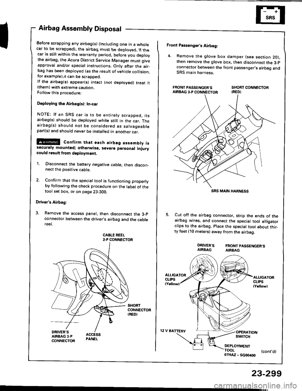
Airbag Assembly Disposal
Before scrapping any airbag(s) (including one in a wholecar to be scrappedl, the airbag must be deployed. t{ thecar is still within the warranty period, before you deplovthe ai.bag, the Acura District Service Manager must giveapproval and/or special instructions. Onlv after the air-ba9 has been deployed (as the result of vehicle collision,for example),it can be scrapped.lf the airbag(s) appear(s) intact (not deptoyed, treat it{them) with extreme caution.Follow this Drocedure:
Doploying the Airbag(sl: In-car
NOTE: lf an SRS car is to be entirely scrapped. itsairbag(s) should be deployed while still in the car. Theairbag(s) should not be considered as salvageablepan(sl and should never be installed in another car.
@ confirm that osch airbsg assembly iss6cursly mounted; oihorwis6. s€voro parsonal iniurycould result from doployment.
1. Disconnect the banery negative cable. then discon_nect the Dositive cable.
2. Confirm that the special tool is functioning properlyby following the check procedure on the label of thetool set box, or on page 23-300,
Driver's Airbag:
3. Remove the access panel, then disconnect the 3_pconnecto. between the driver's airbag and the cablereel.
CABLE REEL3.P CONNECTOR
Front Passonger's Airbag:
4. Remove the glove box damper (see section 2O).then remove the glove box. then disconnect the 3-pconnector botween the front passenger,s airbag andSRS main harness.
FRONT PASSENGER'S SHORT CONNECTORAIRBAG3.PCONNECTOR IRED}
Cut off the airbag connector, strip the ends of theairbag wires, and connect the special tool alligatorclips to the sirbag. Place the special tool about thir_ty feet (10 meters) away from the airbag.
DRIVER'S FRONTPASSENGER'SAIRBAG AIRBAG
12 V BATTERV
ALLIGATORCLIPSlY.llowl
OPERATIONswrTcH
DEPLOYMENTTOOI (cont,dl07HAZ - SG00400
23-299
SRS MAIN I{ARNESS
Page 1410 of 1413
Dash Sensor Replacement
GAUTION:
. Oo not drmrgc the sensor wiring.. Do not instrll used SBS part3 from anothor c!t,When repairing an SRS: use only new part3.o Roplaco. 3onsor it it is dented, crackod, or doform.od.
NOTE; The original radio has a coded theft protectioncircuit. 8e sure to get the customer,s code numberbefore disconnecting the b€ttery cabres,
1. Oisconnect the battery negative cable and then theposative cable.
2. Remove the glove box damper (see section 201.then remove the glove box.
SHOBT CONNECTORIREDI
3. Connect the short connector(s) to the airbag(s).
DRIVER'SAIRBAG
DRNEN'SANAAG3.P CONNECTORSHORTCONNECTORIREDI
SRS MAIN HARNESS
Remove the footrest driver,s side only and door sillmolding, then pull the carpet back, and remove thedash sensor protector. (Left side shownj right sideis similar.)
DASHPROTECTOR
5. Remove the two mounting bolts. then remove thedash ssnsor.
(cont'd)
DASH SENSOB
MOUNTIITG BOLTS
23-305