Page 1202 of 1413
lgnition
lgnition
System
Control Module (lCMl Input Test
NOTE:
a See section I 1 if the malfunction indicator lamD (MlL)
blinks.
a Pertorm an input test for the ignition control module
(lCM) after finishing the fundamental tests for the ig-
nition system and the fuel and emissions systems.
a The tachometer should operate normally.
1. Remove the distributor cap, the distributor rotor, and
the leak cover.
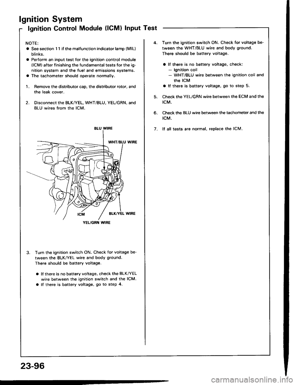
2. Disconnect the BLK/YEL, WHT/BLU, YEL/GRN, and
BLU wires from the lCM.
3. Turn the ignition switch ON. Check for voltage be-
tween the BLK/YEL wire and body ground.
There should be battery voltage.
a lf there is no battery voltage, check the BLK^/EL
wire between the ignition switch and the lCM.
a lf there is battery voltage, go to step 4.
YEL/GRN wlRE
4.Turn the ignition switch ON. Check for voltage be-
tween the WHT/BLU wire and body ground.
There should be battery voltage.
a lf there is no battery voltage, check:- lgnition coil- WHT/BLU wire between the ignition coil and
the ICM
a lf there is battery voltage. go to step 5.
Check the YEL/GRN wire between the ECM and the
tcM.
Check the BLU wi.e between the tachometer and the
rcM.
It all tests are normal, replace the lCM.
6.
7.
23-96
Page 1206 of 1413
Charging System
Troubleshooting
Bofore troubleshooting check- tightness of the alternator belt (see page 23-1Og).- that the malfunction indicator tamp lMlL) of the ECM does not blink. lf it blinks, refer to section 1 1.
lf the charging system light is on, or th€ battery is dead or low, p€rtorm the following tests in the order listed below:
1. Baftery Test (see page 23-66)
2. Charging System Light Test
3. Alternator/RegulatorTest
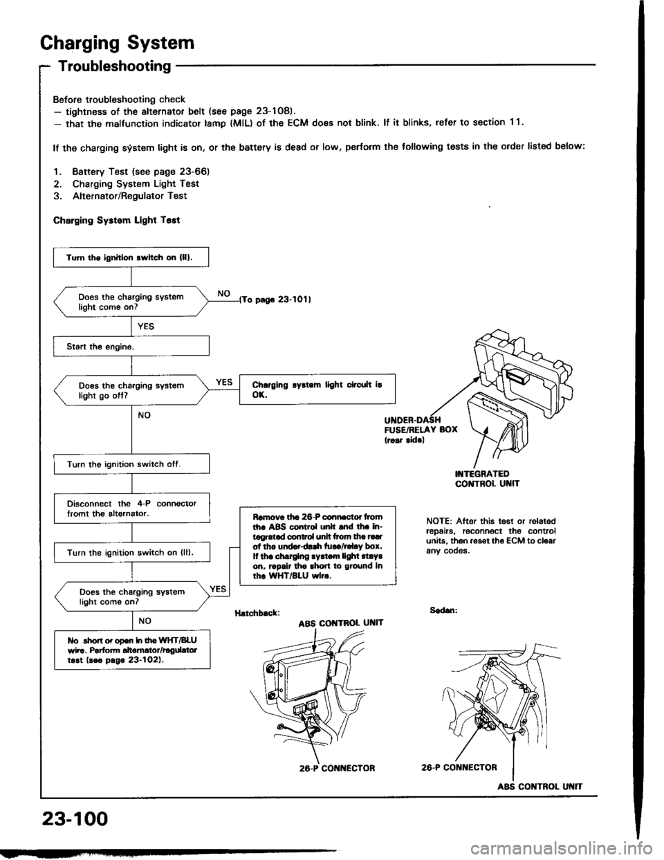
ChErging Sysrom Light T6tt
o pago 23-1011
FUSE/RELAY BOX(r..r tid.)
I'{TEGRATEDCO]TTROL UI{IT
NOTE: After this test or relaledrep6irs, roconnoct the controlunits. th6n aoset th€ ECM to cloarany cooos.
H.tchb.ck:Sad.n:
ABS COI{TROL UNIT
2A-P CONi{ECTOR
23-100
Tu]n tho ignhlon srvitch on (lll.
Does th€ charging syslemlight come on7
Does tho charging systemlight go ott?
Turn the ignition switch otf.
Disconnect the 4-P connoctorlromt th€ altornator.Ramova tfto 26-P connactd tromth. ABS control unh snd lh. in-tggrotad conrol unh ttoln tha tadol tho und..dlrh tu!a/r.l.y box.It thr .hlrglng .yrtom lighl .l.Y.on, rrpalr tho ahon to ground Inrhr WHT/BLU wi...
Turn the ignition switch on {ll),
Does the charging systemlight come on?
tlo rhon o. opon h ih. WIfT/BLUwho. Porfom dtomrtor/rogdttolrost beo pag. 23-l02l.
26.P CON ECTOR
ABS CONTROL
Page 1214 of 1413
Charging System
Alternator Belt Inspection and Adjustment
Deflection Method:
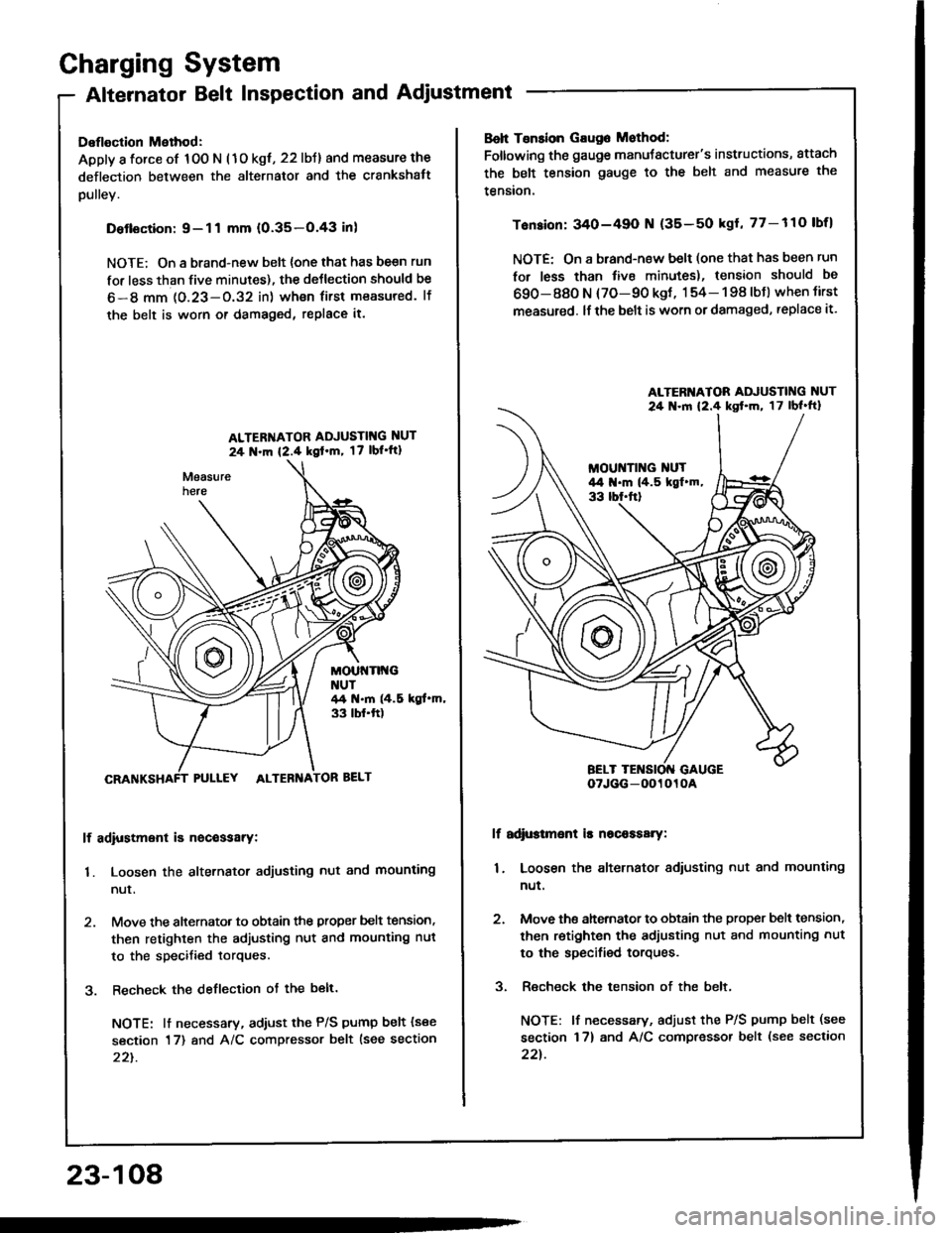
Apply a force of 100 N (1o kgt, 22 lbJ) and measure the
deflection between the alternator and the crankshatt
pulley.
Detlsction:9-11 mm (0.35-O.43 inl
NOTE; On a brand-new belt {one that has be€n run
for less than five minutes), the deJlection should be
6-8 mm 1O.23-O.32 in) wh€n first measured. lf
the belt is worn or damaged, replace it.
ALTER'{ATOR ADJUSTIT{G NUT
24 N.m {2.4 kgl'm, 17 lbl'ft1
MOUt{Tlt{GNUT44 t{.m (4.5 kgt.m,33 tbf.ft)
PULLEY ALTEBNA
lf adiustment is nocessarY:
1. Loosen the alternator adjusting nut and mounting
nur.
2. Move the alternator to obtain the proper belt tension,
then retighten the adjusting nut and mounting nut
to the specified torques.
3. Recheck the deflection ot the belt.
NOTE: lt necessary, adiust the P/S pump belt (see
section 17) and A/C compressor belt lsee section
22t.
23-108
Boh Tsnsion Gaug6 Mothod:
Foltowing the gauge manuJacturer's instructions, attach
the belt tension gauge to the belt and measure the
tension.
Tension: 340-49O N (35-50 kgl, 77-110 lbfl
NOTE: On a brand-new belt (one that has been run
for less than tive minutes), tension should be
690-880 N (70-90 kgt, 154- 198 lbJ) when tirst
measured. lf the belt is worn or damaged, replace it.
lf adi$tmsnt is nscaasary:
1. Loosen the alternator adiusting nut and mounting
nut.
2. Move ths ahernator to obtain the proper bslt tension,
then retighten the adjusting nut and mounting nut
to the specified torques.
3. Recheck the tension of the belt,
NOTE: lf necessary, adjust the P/S pump belt (see
section 17) and A/C compressor belt (see section
22t.
ALTERI{ATOR ADJUSTING NUT
24 .ln 12.4 kst'm, 17lbl'ft}
oTJGG-0O1010A
Page 1215 of 1413
Fan Gontrols
Component Location Index
For the A/C system, see section 22.
UNDER-HOODFUSE/RELAY BOX
RADIAIOR FAN REI.AYTest, page 23-68
CONDCNSER FAI{ BELAYlwir6 color3: ELKnirHT, WHTIIBLUryEL, and BLU/BL( ITest, page 23-68
ENGII{EcooLA TTEMPERATURE{ECT)SwlTCHTesr, page 23-'l 12
FAN MOTORTest, page 23-112
BADIATOR FAN MOTORTest, page 23-1 12
23-109
Page 1228 of 1413
Replacement
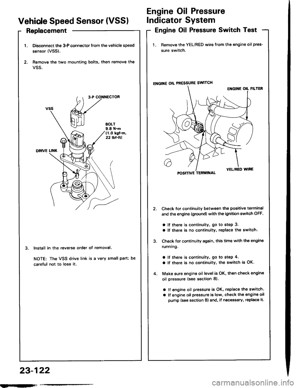
Disconnect the 3-P connector trom the vehicle speed
sensor {VSS).
Remove ihe two mounting bolts, then remove the
VSS.
InstSll in the revsrse order of removal.
NOTE: The VSS drive link is a very small paru
caretul not to lose it.
Engine Oil Pressure
Vehide Speed Sensor (VSSIIndicator System
Engine Oil Pressure Switch Test
1. Remove the YEL/RED wile from the engine oil pres-
sure switch.
ENGI'{E OIL PRESSURE SWITCH
Check tor continuitv between the positive torminal
and the engine {gtound) with the ignhion swhch OFF.
a lf there is continuity, go to step 3.
a lf there is no continuity, replace the switch.
Check for continuity again, this time with th€ engine
runnrng.
a lf there is continuity, go to step 4,
a lf there is no continuity, the switch is OK.
Make sure engine oil level is OK, then check engin€
oil pressure (s€e section 8).
a lf engine oil pressure is OK, replace the switch'
a lf engine oil pressure is low, check the sngine oil
pump (see section 8) and, if necessary, replac€ it.
POSITIVE TERMII{AL
23-122
nlmlliitl
Page 1229 of 1413
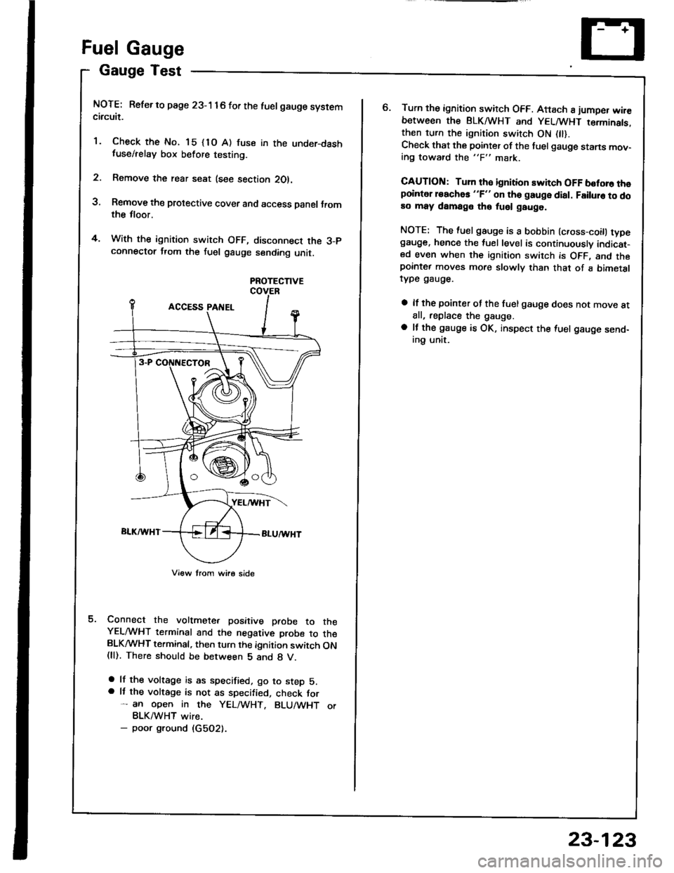
Fuel Gauge
Gauge Test
NOTE: Refer to page 23-1 16 for the luelgauge systemcircuit.
'1. Check the No. 15 {1O A) fuse in the under-dashfuse/relay box before testing.
2. Remove the rear seat (see section 2Ol.
3, Remove the protective cover and access Danel Jromthe tloor.
4. With the ignition switch OFF, disconnect the 3-pconnectot from the fuel gauge sending unit.
PROTECTIVE
Connect the voltmete. positive paobe to theYELMHT terminal and the negative probe to theBLKMHT terminal, then turn the ignition switch ON(ll). There should be between 5 and 8 V.
a lf the voltage is as specified. go to step 5.a It the voltage is not as specified, check for- an open in the YEL/WHT. BLU/WHT orBLK/WHT wire.- poor ground (G5O2).
o.Turn the ignition switch OFF. Attach 8 jumper wir€between the BLKA HT and YELMHT terminats.then turn the ignition switch ON 0l).Check that the pointer of the fuel gauge starts mov-ing toward the "F" mark.
CAUTION: Turn th€ ignition switch OFF boforo thepointer roachas "F" on tho gauge dial. Failuro to doao may damage tho fuel gauge.
NOTE: The fuel gauge is a bobbin (c.oss-coitl typegauge. hence the tuel level is continuously indicat-ed even when the ignition switch is OFF, and thepornter moves more slowly than that of a bimetalrype gauge.
a lf the pointer of the fuel gauge does not move atall, replace the gauge.
a lf the gauge is OK, inspect the {uel gauge send-ing unit.
23-123
Page 1230 of 1413
Fuel Gauge
Sending Unit Test/Replacement
@ oo not lmoke while working on tho fuol
system. Kaop open flamos away from your wotk aroa.
1. Remove the rear seat (see section 2O).
2. Remove the protective cover and access panel lrom
the floor.
3. With the ignition switch OFF, disconnect the 3-P
connector from the fuel gauge sending unit.
4. Remove the tuel gauge s€nding unit.
5. Measure the resistance between the A and B termi-
nals at E (empty), 1/2 (half full) and F (full) by mov-
ing the tloat.
6. Check the change in resistance by moving the float
uo and down.
(
lf unable to obtain the above readings or it resistance
do€s not change, replace the fuelgauge sending unit.
Float PositionE
Resistance lO)105-11025.5-39.52-5
o
23-124
Page 1268 of 1413
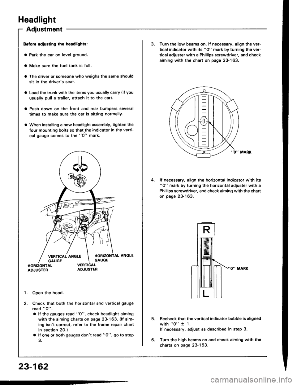
Headlight
Adjustment
Belol€ adiusting lha hoadlights:
a Park the car on level ground.
a Make sure the luel tank is full.
a The driver or someone who weighs the same should
sit in the driver's seat.
a Load the trunk with the items you usually carry (if you
usually pull a trailer, attach it to the carl.
a Push down on the tront and rear bumDers several
times to make sure the car is sitting normally.
a When installing a new headlight assembly, tighten the
four mounting bolts so that.the indicator in the verti-
cal gauge comes to the "O" mark.
1. Open the hood.
2. Check that both the horizontal and vertical gauge
read " O" .
. lf the gauges rcad "O", check headlight aiming
with the aiming charts on page 23-163. (lf aim-
ing isn't correct, refer to the trame repair chart
in section 20.)
a lf one o. both gauges don't read "O". go to step
23-162
3. Turn the low beams on. lJ necessary, align the ver-
tical indicator with its "O" mark by turning the ver-
tical adiuster with a Phillips screwdriver, and check
aiming with the chart on page 23-163.
lf necessary, align the horizontal indicator with its"0" mark by turning the horizontal adjuster with a
Phillips screwdriver, and check aiming with the chart
on page 23-163.
4.
5.Recheck that the vertical indicator bubble is aligned
with "o" 1 1.
lf necsssary, adjust as described in step 3.
Turn the high beams on and check aiming with the
charts on page 23-163.