Page 1339 of 1413
Power Door Locks
Component Location Index
1
FRONT PASSENGER'S DOOR LOCK ACTUATORTest. pago 23-239Reolacement. section 20
FRONT PASSENGER'SDOOR LOCK SWITCHfest, page 23-241
FRONT PASSENGER'S DOOR KEYCYLII{DER SWITCHTest, page 23-240
POWER OOOR LOCKCONTROL UNITfnput Tost, page 23-236
RIGHT REAR DOOR LOCK ACTUATOR lsodanlTest,
DOORKEY CYLINDER SWITCHTest. page 23-24O
DBIVER'S
DOOR
LOCK ACTUATORTest, page 23-238Roplacement, seclion 20
LOCK SWITCH'lest, page 23-241
Description
For this model, a new door lock system has been adopted to improve convenience and safety. lf the kev is insened intothe driver's door key cylinder, turned to the unlock position, and pulled out immediately thereafter, oNLy the driver.sdoor will unlock. However, if the key is kept in the unlock position tor one second or more, ALL doors wi
unlock.
23-239
LEFT REAR DOOR LOCK ACTUATOR {Sodan}Test, page 23-239
23-233
Page 1342 of 1413
Power Door Locks
Control Unit Input Test
Remove the driver's door panel {see section 2O).
Disconnect the 1+P connector Jrom the control unit.
Inspect the connector and socket terminals to be
sure they are all making good contact.
a It the terminals are bent. loose or corroded, repair
them as necessary. and recheck the system.
a lf the terminals look OK. make the following in-
put tests at the connector.- lf any test indicates a problem, find and cor-
rect the cause, then recheck the syslem.
lf all the input tests prove OK, the control unit
must be faultv; replace it.
POWER DOOR LOCK
CONTROL UNIT
t4-P COI{NECTOR
View from wiro side
23-236
Page 1344 of 1413
1.
Power Door Locks
Driver's Door Lock Actuator Test
Remove the door panel (see section 20).
Disconnect the 6-P connector from the actuator.
Check actuator operation by connecting power and
ground according to lhe table.
CAUTION: To prevont damago lo tho actualol, ap-
ply battery voltage only momentarily.
lf the actualor fails to work properly, replace it.
Terminal
;;"
---\D
LOCK@o
UNLOCKlJ@
23-238
Terminal
il;----tI
LOCKoo
UNLOCKo--o
5. Check fo. continuity between the terminals in each
switch position according to the table.
DOOR LOCK KI{OB
Page 1345 of 1413
Passenger's Door Lock Actuator Test
1. Remove the door panel (see s
2. Disconnect the 2-P connector
Front Passonger's Door:
terminal side
2-PCONNECTOR
section 20).
r from the actuator.
Rear Passenger's Dool:
NOTE: Left rear actuato, is shown, right rear actuator
is similar.
View from terminal side
Check actuator operation by connecting power andground according to the table.
CAUTION: To prevent damage to the actuator, ap-ply battery voltage only momentarily.
4. It the actuator fails to work properly, replace it.
ACTUATOR
Terminal
Position \
B
LOCK@
UNLOCK@,-,
23-239
Page 1346 of 1413
Power
Driver'
Door
s Dool
Locks
Key CylinderFront Passenger's Door Key Gylindet
Switch Test
1. Remove the door Danel {see section 2O).
2. Disconnect the 3-P connector trom the switch.
FRONTPASSENGER'SDOOB KEYCYLINDERswtTcH
coN ECIOR
3. Check tor continuitv between the terminals in each
switch position according to the table.
tfil*rr
Terminal
P""ft;---lABc
LOCKo----o
OFF
UNLOCKo----o
UNLOCK
-r--O
I LOCK
Switch Test
1. Remove the door panel (see section 20).
2. Disconnect the 2-P connector from the switch.
terminal side
3. Check for continuity between the terminals in each
switch position according to the table.
Position
TerminalB
UNLOCKGo
OFF
UNLOCK<
I
23-240
Page 1357 of 1413
Brake Switch Test
'1. Disconnect the 4-P connector from the switch.
2. Check for continuitv between the terminals accord-
ing to the table.
3. It necessary, replace the switch or adjust pedal
height {see section 19).
Glutch Switch Test (M/T)
I� Disconnect the 2-P connector from the switch,
2. Check {or continuitv between the terminals accord-
ing to the table.
3. lf necessary, replace the switch or adjust pedal
height (see section 12).
I
Terminal
il"*on---\B
BELEASEDo---o
PUSHED-o
| ormtnal
Clutch podal \
RELEASEDoo
PUSHED
23-251
Page 1358 of 1413
Cruise Control
A/T Gear PositionSwitch Test
1.Remove the center console, then disconnect the
14-P connector trom the switch.
Check for continuitv between the terminals in each
switch position according to the table.
NOTE:
a Move the lever back and forth at each position
without touching the button, and check for con-
tinuity within the range of free play ot the shift
lever.
a ll there is no continuity within the range of free
play, adjust the installation position of the switch.
View trom terminal side
ABCDEFG
3. lf necessary, replace the switch (see section 13).
HIJKLM
A/T Gear Position Swhch (For cruis€ control)
Terminal
il;---t
tr
ao
Eo
lu4lo---o
N
B
E
23-252
Page 1359 of 1413

1.
2.
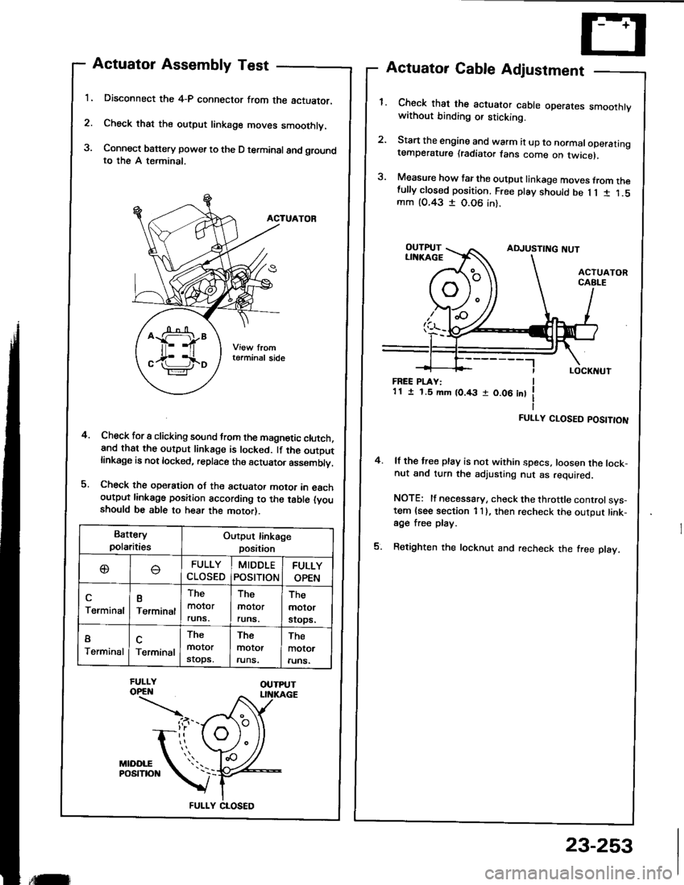
3.
Actuator Assembly Test
Disconnect the 4-P connector from the actuator.
Check that the output linkage moves smoothly.
Connect battery power to the D terminal and groundto the A terminal,
ACTUATOR
Check for I clicking sound trom the magnetic clutch,and that the output linkage is locked. lf the outDutlinkage is not locked, replace the actuator asssmblv.
Check the operation oJ the actuator motor in eachoutput linkago position according to the table (youshould be able to hear the motor).
Actuator Cable Adjustment
Check that the actuator cable operares smoothtvwithout binding or sticking.
Start the engine and warm it up to normaloperatingtemperature (radiator fans come on twicel,
Measure how far the output linkage moves from thefully closed position. Free play should be 1 1 1 1.5mm (O.43 I 0.06 in).
4.
FREE PLAY:1 1 I 1.5 mm (0.43 r 0.06 int
FULLY CLOSED POSITION
4. lf the free play is not within specs, loosen the lock-nut and turn the adjusting nut as required.
NOTE: lf necessary, check the throttle controlsys-tem {see section 1 I }, then recheck the output link-age free play.
5. Retighten the locknut and recheck the free play.
Battery
polaritiesOutput linkage
position
oFULLY
CLOSED
MIDDLE
POStTtON
FULLY
OPEN
Terminal
B
Terminal
The
molor
runs.
The
molor
runs.
The
molor
srops.
I
TerminalTerminal
The
motor
stops.
The
motor
runs.
The
motor
runs.
FULLY CLOSED
,tilr
23-253