Page 1328 of 1413
Power Windows
Component LocationIndex
POWER WINDOW RELAYTest, page 23-68UI{DER-DASHFUSE/RELAY BOX
FOWER WINDOWMASTER SWITCH{Has built-in control unitlfnput Test, page 23-226, 228Tost, page 23-229, 23ORopfacement, page 23-231
FRONT PASSEI{GER'S WII{DOW SWITCHTest, page 23-230Repf acement. page 23- 231
FRONT PASSENGER'S WII{DOW MOTORfosr, page 23-232
RIGHT REAR Wll{DOW SWITCH (Sodrn}
Tost, page 23-230Replacement, page 23-231
RIGHT REAR WII{DOW
MOTOR (Sod.nl
Test, page 23-232
DBIVER'S WINDOW MOTORTest, page 23-232
LEFT REAR WINDOW MOTOB {S6dan)Test. page 23-232
LEFT REAR Wlt{DOW SWITCH lsodanlTest, page 23-230Repfacement, page 23-231
23-222
Page 1329 of 1413
UNOER-HOOO FUSE/RELAY 8OX
Circuit Diagram (Sedanl
G20rG401
UNDER_ DASH FUSE/RELAY BOX
LEFT REARWINDOWMOTORRIGHT REAN WINOOWMOTORFROI{T PASSENGER'SwrNoow i,roToRG501G502
DRiVER'S WINOOW MOTOR
23-223
Page 1330 of 1413
Power Windows
Circuit Diagram (Hatchback)
UNDER - HOOD FUS€/REI.AY BOX
tlo.41 l100Al ilo.39 {50A)
UNOER- OASH FUSE]NEI.AY 8OX
8LX z
G50tG502
D PASSENGER'SwrNDowswITcH
PASSENGEN'SwtN00w M0T0nG401
23-224
Page 1333 of 1413

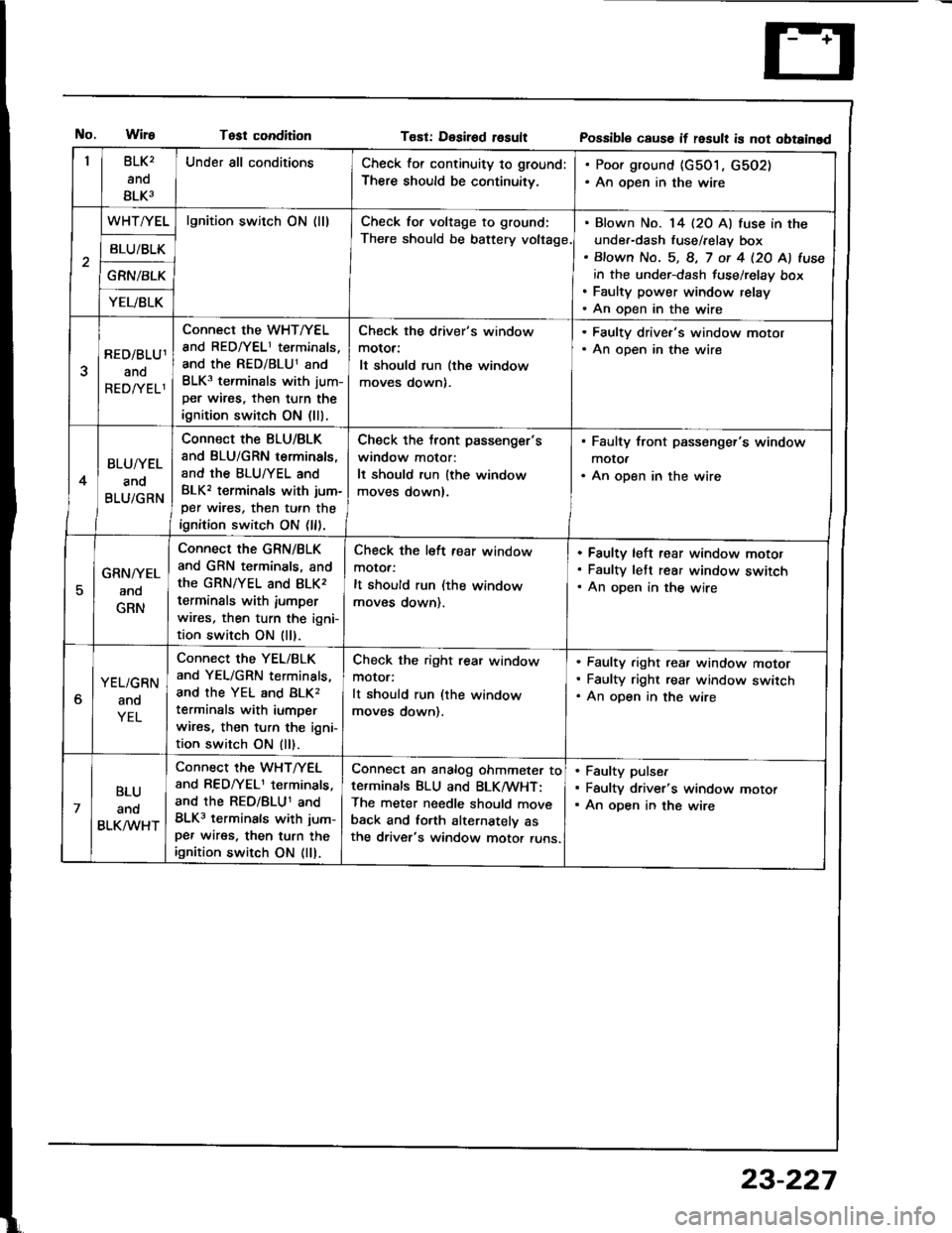
Test conditionT€st: Desirod rosultPossibl€ cause if result is not obtainad
BLK2
ano
BLK3
Under all conditionsCheck for continuity to ground:
There should be continuitv,
. Poor ground {c501, G502). An open in the wire
WHT/YELlgnition switch ON (lllCheck for voltage to ground:
The.e should be battery voltage.
Blown No. 14 (20 Al fuse in the
under-dash fuse/relay box
Bfown No. 5, 8, 7 ot 4 l2O Al fuse
in the under-dash fuse/relay box
Faulty power window relay
An open in the wire
BLU/BLK
GRN/BLK
YEL/BLK
RED/BLU1
ano
REDATELl
Connect the WHT/YEL
and RED/YEL1 terminals,
and the RED/BLU1 and
BLK3 terminals with jum-
per wires, then turn the
ignition switch ON (lll.
Check the driver's window
motor:
It should run (the window
moves down).
. Faulty drivea's window motor. An open in the wire
4
BLU/YEL
and
BLU/GRN
Connect the BLU/BLK
and BLU/GRN terminals,
and the BLU/YEL and
BLK, terminals with jum-
per wires, then turn the
ignition switch ON (ll).
Check the tront passenger's
window motor:
It should run {the window
moves down).
. Faulty front passenger's window
motOa. An open in the wire
5
GRN/YEL
ano
GRN
Connect the GRN/BLK
and GRN terminals, and
the GRN/YEL and 8LK,
terminals with iumperwires, then turn the igni-
tion switch ON (ll).
Check the left fear window
motor:
It should run (the window
moves down).
Faulty left rear window motof
Faulty lett rear window switch
An oDen in the wire
6
YEL/GRN
and
YEL
Connect the YEL/BLK
and YEL/GRN terminals,
and the YEL and BLK,
terminals with iumper
wires, then turn the igni-
tion switch ON (ll).
Check the right rear window
motor:
It should run (the window
moves down).
Faulty .ight rea. window motor
Faulty right rear window switch
An open in the wire
7
BLU
ano
BLK/VVHT
Connect the WHT/YEL
and RED/YEL1 terminals.
and the REo/BLU1 and
BLK3 terminals with jum-
per wires. then turn theignition switch ON (ll).
Conned an analog ohmmeter tote.minals BLU and BLK/wHT:
The meter needle should move
back and lorth alternatelv asthe driver's window motor runs.
Faulty pulser
Faulty driver's window motor
An open in the wire
23-227
Page 1334 of 1413

Power
Master
Windows
Switch lnput Test(Hatchback)
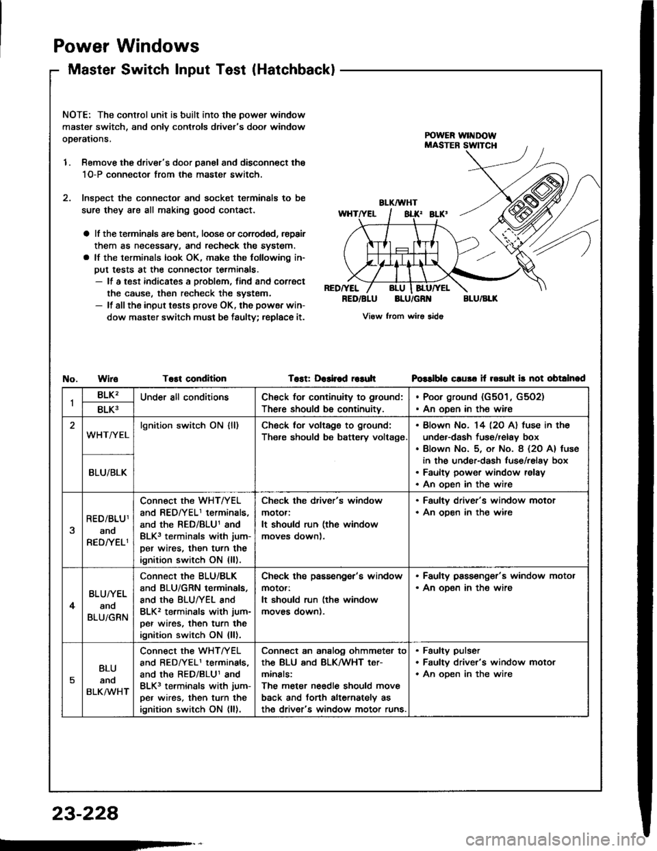
NOTE: The control unit is built into the power window
master switch, and onlv controls driver's door window
operations,
1. Remove the driver's door panal and disconnect the
1O-P connectol from the master switch.
2. lnsDect the connector and socket terminals to be
sure they are all making good contact.
a lf the terminsls arc bent, loose or corroded, rspair
them as necessary, and recheck the system.
a lf the terminals look OK, make the following in-
put tests at the connector terminals.- lf a test indicates a problem, find and correct
the cause, then recheck the systsm.- lf all the input tests prove OK, the powsr win-
dow master switch must be faulty; replace it.
RED/YEL
RED/BLUBLU/GR'{BLU/BLK
View from wirs sido
WiroTost conditionTost: Dashod r€suhPGslblo cluso if rosuh ir not obtalnad
1BLK'Under all conditionsCh€ck for continuity to ground:
There should be continuity.
Poor ground (G501, G5O2)
An oDen in the wire8LK3
WHT/YELlgnition switch ON {ll)Ch6ck for voltags to ground:
Th€re should be battery voltage.
Blown No. 14 l2O Al fuse in the
under-dash fuso/relay box
Blown No. 5, or No. 8 (2O A) tuse
in the under-dash luse/relay box
Faulty power window relay
An oDen in the wire
BLU/BLK
RED/BLU1
ano
RED/YELI
Connect the WHT/YEL
and REDfYELI terminals,
and the RED/BLU1 and
BLK3 terminals with jum-
per wires, then turn the
ignition switch ON {ll).
Check the driver's window
motor:
It should run (the window
moves down).
. Faulty driver's window motor. An ooen in th€ wire
4
BLU/YEL
and
BLU/GRN
Connect the BLU/BLK
and BLU/GRN terminals,
and the BLUTYEL and
BLK2 terminals with jum-
per wires, then turn the
ignition switch ON {ll).
Check ths passengor's window
motor:
It should run (the window
moves down).
. Faulty pass€nger's window motor. An oD€n in the wire
5
BLU
anq
BLKMHT
connect the WHTTYEL
and BEDrYELI terminals,
and the RED/BLU1 and
BLK3 terminals with jum-
pe. wires, then turn the
ignition switch ON (ll).
Conn€ct an analog ohmmeter to
thE BLU ANd BLKMHT t€Tr
minals:
The meter needle should move
back and torth alternately as
th€ driver's window motor runs.
Faulty pulser
Faultv driver's window motor
An oDen in the wire
23-228
Page 1340 of 1413
Power Door Locks
Circuit Diagram
BATTENY
@'"t
BLK
.&;
G201G401
o00R toc( KN08
VL____I
FROMTPASSENGER'SoooR t-ocKACIUATOR
@r
I uFt REAR000R LocKACTUATOR
@"
r RIGHT REAR000R LocKACTUATOR
@'
8LK
A=
G501G5o2
I
G501G5o2
UiIDER- HOOD FUSE/RELAY BOX
No.41 l100Al iJo,36l50A)
DRIVER'S OOOBKEY CYI,INDERswITcH
DRIVER'SoooR rocKswtTcH
FRONTPASSENGEN'SDOOR LOCKswncH
POWER OOORLOCK CONTROI.
8rl(
A-l
GSotG502
23-234
I
Page 1343 of 1413

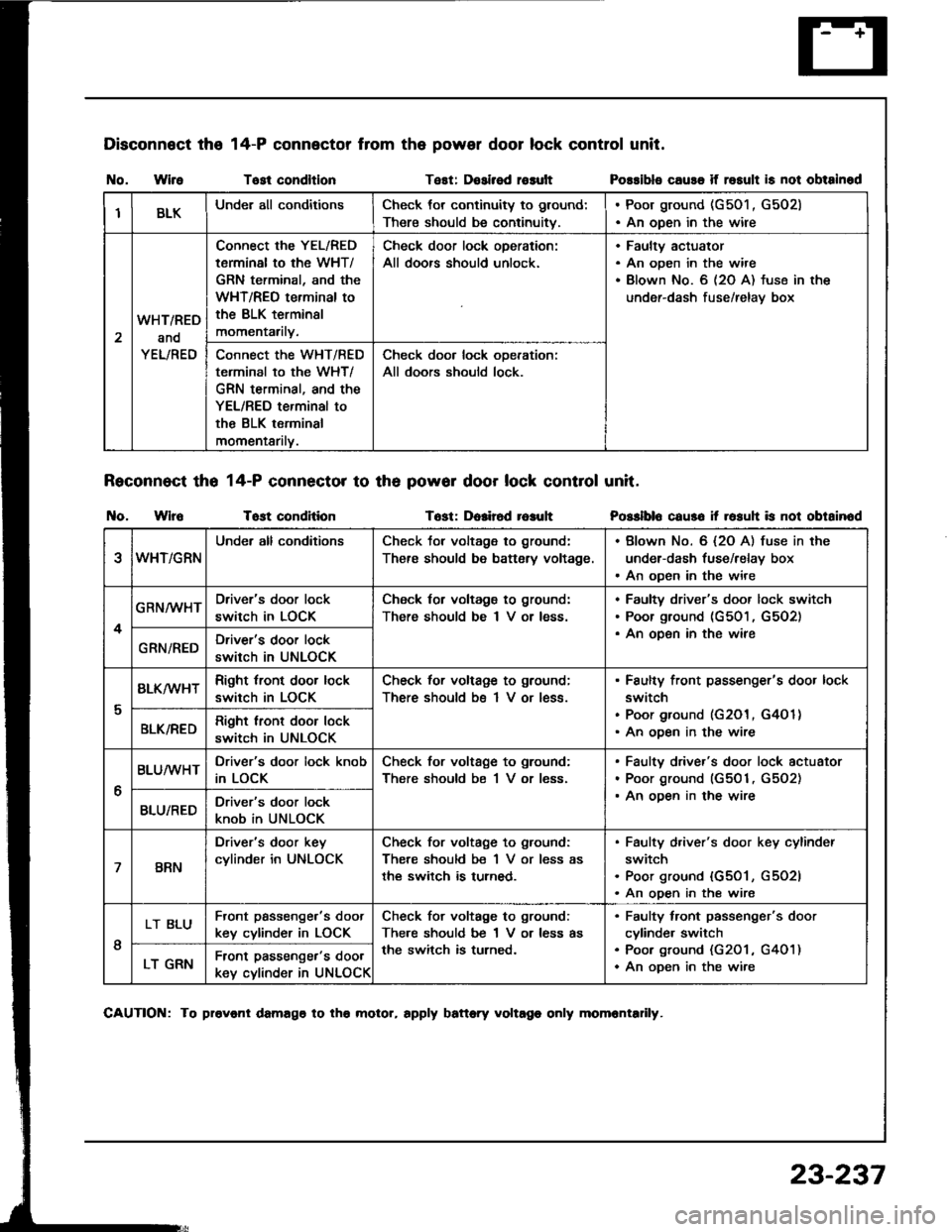
Disconnect the
I{o. WireTost condltlonTest: Dosirsd rosult
Reconnect tho 14-P connector to th6 powor door lock control unit.
t{o. WlroTost conditionTost: Dolir6d r6auh
14-P connector from the power door lock control unit.
Possibls cause if rosult is not obtainod
Posslblo caus6 it rosuh is not obtainod
IBLKUnder all conditionsCheck tor continuity to ground:
There should be continuitv.
. Poor ground (G501 , G502). An open in the wire
2
WHT/RED
and
YEL/RED
Connect the YEL/RED
tarminal to the WHT/
GRN terminal, and the
WHT/REO terminal to
the BLK terminsl
momentarily.
Check door lock oDeration:
All doors should unlock.
Faultv actuator
An open in the wire
Blown No. 6 (2O A) fuse in the
under-dash fuse/relav box
Connect the WHT/RED
terminal to the WHT/
GRN terminal, and the
YEL/RED terminal to
the BLK terminal
momentarilv.
Check door lock ooeration:
All doors should lock.
eWHT/GRN
Under all conditionsCheck tor voltage to ground:
There should be battsry voltage.
. Blown No. 6 {2O A) fuse in the
under-dash fuse/relay box. An open in the wire
4
GRN/WHTDriver's door lock
switch in LOCK
Check for voltagg to ground:
There should be I V or less.
Faultv driver's door lock switch
Poor ground (G501, G5O2)
An oDen in the wireGRN/REDDriver's door lock
switch in UNLOCK
I
BLK/wHTRight tront door lock
switch in LOCK
Check for voltage to ground;
There should bs 1 V or less.
Faulty front passenger's door lock
switch
Poor ground (G201, G4O 1)
An ooen in the wireBLK/REDRight lront door lock
switch in UNLOCK
6
BLUMHTDriver's door lock knob
in LOCK
Check for voltage to ground:
There should be 1 V or less.
Faulty driver's door lock actuator
Poor ground (G501, G5O2)
An ooen in the wireBLU/REDDriver's door lock
knob in UNLOCK
7BRN
Driver's door key
cylinder in UNLOCK
Check for voltage to ground:
There should be 1 V or less as
the switch is turned.
Faulty d,iver's door key cylinder
switch
Poor ground {G501, G5O2l
An open in the wire
I
LT BLUFront passenge.'s doot
key cylinder in LOCK
Check for voltage to ground:
There should be 1 V or less as
the switch is turned.
Faulty tront passenger's door
cylinde. switch
Poo. ground (G201 , G401)
An oDen in the wireLT GRNFront passenger's door
key cylinder in UNLOCK
CAUTION: To provonl damago to tho molor, rpply battory voltago only momrntadly.
23-237
Page 1350 of 1413
+ No.24 ll5Al: 81881 onoineNo.24 l20Al: 818C1 ensine
UNDER-DASH FUSE/RELAY BOX
HORN
Y
UNOER _HOOD FUSE/RELAY BOX
No.4l (100A) No.39l50A)
INDICATORTIGHT{0,91W}
IP
I D Suur
6yffi Bi,G#,,'.
BTK
t-
G201G401
II
I
f7
VEHICLE SPEEDSENSOR iVSS)
M/r : CLUTCH SWITCH IA/T : A/T GEAR IPOS|T|oN SWTTCH IInIEI,E) I
PNK
BI-K
T
G201G401
Cruise Gontrol
Circuit Diagram
23-244