Page 1250 of 1413
Integrated Control Unit
Circuit Diagram
D.3c ptlon
An integrat€d control unit, located in the left kick panel, integratss the functions of tho keyin/seat beh r6mind€r, sido
markar light {lasher, wiper/washer, lights-on r6minder, rear window dsfogger timer, brak€ system light bulb check, and
enging oil pressure indicator flasher circuitE,
NOTE: Difforent wires with the same color have be6n given a numbor suffix to distinguish them (for Example,
GRN/RED1 and GRN/RED'� are not the same).
WNOSHIELD WIPER/WASHER SWITCH
IMT OFFiINT
I
II
IIIIIIIIIIII
YEUEE
rl
t
P
UNOER - DASH FUS€/RETAY BOX
r NTEGRATED COI{TROI UNIT
t-0wErGrilE 0|lPRESSI'REINDICATORLIGI{T
WINDSHIELOWIPERAVASHERswtTcH
tr-/
IBLK/GRN BI
WINDSHIELOWIPERMOTOR{Asl
VOLTAGEREGULATOR{ln ahamator,
UNOER- HOOD FUSE/RELAY 8OX
I
r3
r8relit;rBt5I
23-144
lr ) : With combinod washef-wip€r oporation
Page 1251 of 1413
Br-u/Brx + fr,rTrtl.* r*r.,
/\JL
r--------Y----__tfl
I moani PosrIoN swtTcH
t,x*rt €- BLK/RE9 -tv-----J
UND€R - OASH FUSE/REI-AY 8OX
ERAKESYSTEMI.IGHTll.4wl
3
a
Et.?
SEAT 8EI-TREMIi/OERLIGHTt1.4Wl
YEI-
RED/BLU
RIGHTFRONTSIDEMASKERI,IGHTt3cP'
| *rt
QiftHl.| (3CP,
IBI..K
{
G30l
I
I
I
a'u, [!
tsl
IBI-K
{
G20rG40l
23-145
Page 1253 of 1413

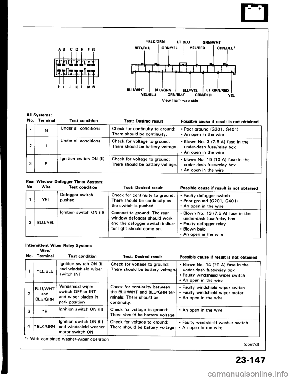
1NUnder all conditionsCheck for continuity to ground:
There should be continuitv.
. Poor ground (G201, G4O1). An open in the wire
Under all conditionsCheck for voltage to ground:
There should be battery voltage.
. Blown No. 3 (7.5 A) fuse in the
under-dash fuse/relay box. An oDen in the wire
F
lgnition switch ON {ll)Check for voltage to ground:
There should be bsttery voltage
. Blown No. 15 (10 A) tuse in the
under-dash fuse/relay box. An open in the wire
All Systems:
No. TsrminalT€st condition
R€ar Window Detogger Timer System:
No. WireTost condition
Intermittent Wip6r Relay System:
Wir€/
No. TerminalTest condition
T6st: Desired rosult
Test: Dosiled result
T€Et: Desir6d result
Possibla cause it result is not obtained
Possible cause il rosult i8 not obtained
Possiblo cause if rosult is not obtained
(cont'd)
IYEL
Defogger switchpushedCheck lor continuity to ground:
There should be continuity asthe switch is Dushed.
Faulty defogger switch
Poor ground {G201, G4O1}
An open in the wire
BLUiYEL
lgnition switch ON (ll)Connect to ground: The rear
window defogger should work
and the detogger switch indica-
tor light should come on.
Blown No. 13 {7.5 Al fuse in the
under-dash fuse/relay box
Faulty defogger relay
Blown bulb
An open in the wire
,|YEL/BLU
lgnition switch ON (ll)
and windshield wipet
switch INT
Check tor voltage to ground:
There should be battery voltage
Bfown No. '14 l2O Al fuse in the
under-dash fuse/relay box
Faulty windshield wiper switch
An oDen in the wire
BLU/WHT
ano
BLUiGRN
Windshield wiper
switch OFF or INT
and wiper blades inpark position
Check for continuity between
the BLUMHT and BLU/GRN ter-minals: There should be
continuity.
Faulty windshield wiper switch
Faultv windshield wiDer motor
An open in the wire
.Elgnition switch ON (lllCheck for voltage to ground:
There should be battery voltage.
. An open in the wire
*BLK/GRNlgnition switch ON (ll)
and windshield washer
motor switch ON
Check for voltage to ground:
There should be battery voltage.
. Faulty windshield washer switch. An open in the wire
*: With combined washer-wiper operation
23-147
Page 1254 of 1413

Integrated Control Unit
Input Test (cont'd)
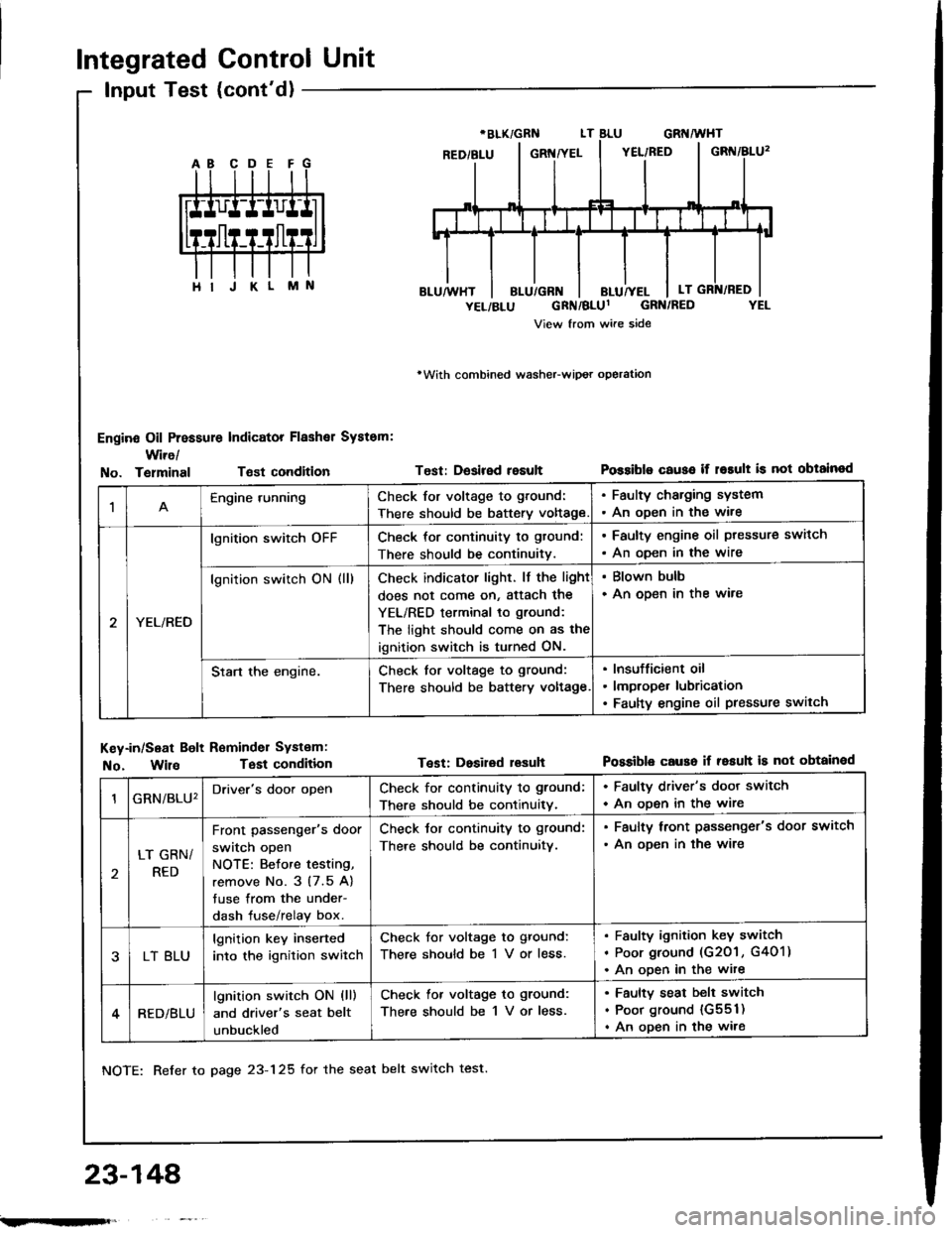
Engine Oil Pressure Indicator Flashal System:
Wire/
rWith combined washeFwipot operation
Test: Desired resultPossiblo c€use if r6rult is not obtainodNo. TelminalTsst condition
M
1Engine runningCheck for voltage to ground:
There should be battery voltage
. Faulty charging system. An oDen in the wire
YEL/RED
lgnition switch oFFCheck for continuity to gtound:
There should be continuitv.
. Faulty engine oil ptessure switch
. An oDen in the wire
lgnition switch ON (ll)Check indicator light. lf the light
does not come on, Sttach the
YEL/RED terminal to ground:
The light should come on as the
ignition switch is turned ON.
. Blown bulb. An open in the ware
Start the engine.Check for voltage to ground:
There should be battery voltage
Insufficient oil
lmproper lubrication
Faulty engine oil pressure switch
Key-in/Seat Bolt Reminder Systam:
No. WilaTest condition
NOTE: Refer to page 23-125 for the seat belt switch test.
Test: Dosired lesuhPossible causo if resuh is not obtainod
23-148'
GRN/BLU'Driver's door openCheck for continuity to ground;
There should be continuitv.
. Faulty driver's door switch
. An ooen in the wire
LT GRN/
RED
Front passenger's door
switch open
NOTE: Betore testing,
remove No. 3 (7.5 A)
tuse from the under-
dash fuse/relay box.
Check tor continuity to ground:
There should be continuitv.
. Faulty lront passenger's door switch
. An ooen in the wire
LT BLU
lgnition key inserted
into the ignition switch
Check for voltage to ground:
There should be 1 V or less.
Faulty ignition key switch
Poor ground (G201 , G401)
An ooen in the wite
RED/BLU
lgnition switch ON (ll)
and driver's seat belt
unbuckled
Check lor voltage to ground:
There should be 1 V or less.
Faulty seat belt switch
Poor ground {G551)
An open in the wire
;.rqFft,
Page 1255 of 1413

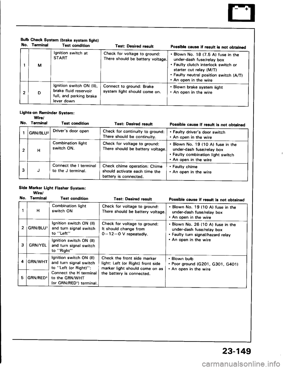
Bulb Check System
No. Tsrminal
(blake system lightl
Test condition
Lights-on Romind6r Systom:
Wire/
No, ToiminalT6Et condition
Side Markol Light Flashar System:
Wiro/
No. TerminalTest condition
Tost: Desirod resuhPossibls caus6 it result is not obtainod
Tost: Dositod rosuhPossibl6 caus6 if rosuh is not obtainod
Tast: Desired rosultPo$ible cause if result is not obtained
IM
lgnition switch at
STARTCheck lor voltage to ground:
There should be battery voltage.
Blown No. 18 {7.5 Al fuse in theunder-dash fuse/relay box
Faulty clutch int€rlock switch or
starter cut relay {M/T}Faulty neutral position switch (A/T)
An open in the wire
D
lgnition switch ON (ll),
brake fluid reservoir
tull, and parking brake
lever down
Connect to ground: Brake
system light should come on.
. Blown brake system light. An oDen in the wire
GRN/8LU'Driver's door openCheck for continuity to ground:
There should be continuity.
. Faulty driver's door switch. An oDen in the wire
H
Combination light
switch ON.
Check for voltage to g.ound:
There should be battery voltage
Blown No. l9 (1O A) tuse in the
under-dash fuse/relav box
Faulty combination light switch
An oDen in the wire
5
Connect the I terminal
to the J terminal.
Check chime operation: Chime
should activate each time the
batterv is connected,
. Faulty chime. An open in the wire
1H
Combination light
switch ON
Check for voltage to ground:
There should be battery voltage
. Blown No. 19 (1O A) tuse in the
under-dash fuse/relay box. An open in the wire
GRN/BLU1
lgnition switch ON {ll)and turn signal switch
to "Left"
Check for voltage to ground:
It should change from
O-12-O V repeatedly.
Blown No. 26 (10 A) luse in theunder-dash fuse/relav box
Faulty turn signal/hazard relay
An oDen in the wire2GRN/YEL
lgnition switch ON {ll)and turn signal switch
to "Right"
4GRN/WHTlgnition switch ON (ll)
and turn signal switch
to "Left (or Rightl":
Connect the H terminal
to the GRNMHT(or GRN/REDl) terminal.
Check the front side marker
light: Left (or Right) front sidemarker light should come on asthe batterv is connected.
Blown bulb
Poor ground (G2O1, c3O1, G4O1lAn open in the wire
GRN/REDl
23-149
Page 1261 of 1413
Gircuit Diagram (Canadal
BATTERY
G"*
UNOER_HOOD FUSEiRETAY 8OX
coMBrNAtor{ rcHrswnc
-il w
| '.=r" I
ll'L I I
I I *o\." l-'li' ;- ;j
I LI
"- r.r-,9 "orr
I
d "
L
RED/BLU REO/}VHT RED,ll
I UNDEN-DASH II FUSEiIEI,AY 8OX I
tl
L-J
t'GRN
/d\BATtG2\9-l
rGNrTrot{swITcH
No.2lfl0A)\I
No.l9|l04]Jm.tr (
t10A) ttt
I
No.l6{7.54}
tl
i,"#
llrrff li'rrt,
RED/GRtIIBLU REOr'TVHTINED/B
V
WHTTYEL
. DASH LGHTS BRIGHTNESSCOI{TROLLER. DASH I-IGHTS. PARKING I-GHIS. TAII,LIGHTS. UCENSE N"AT€ LIGI{TS
I a-rneonru jllA/Vr l"o I f# wxrintoRED/GRI{ +\{H I
DAYTIME RUNNINGUGI{TS RESISTOR
IRED/GRN
Hr I r-01651,1/) | l55W)HIt85W)LOt55Wl
HIGH BEAMINOICATORUGHTfl.4W
I
RIGHTHEADLIGHTPARKIIIGBRAKEsw{TcH
23-155
Page 1263 of 1413

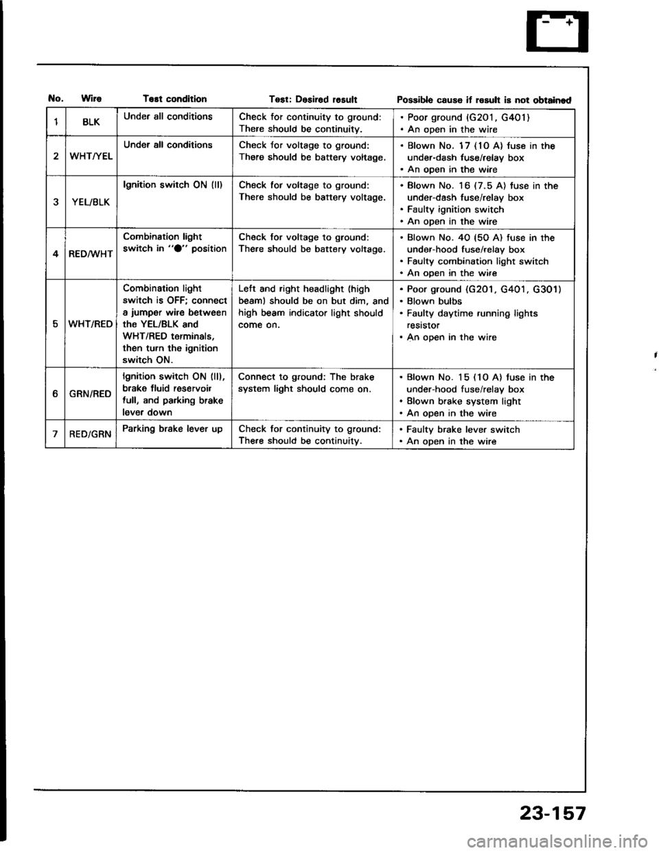
T€st conditionTest: Desirad losultPossibla cause if rosult is not obtainad
1BLKUnder all conditionsCheck for continuity to ground:
There should be continuity.
. Poor ground {G201, G401). An open in the wire
WHT/YEL
Under all conditionsCheck Jor voltage to ground:
There should be battery voltage.
. Blown No. 1 7 { 10 A} luse in the
under-dash tuse/relay box. An ooen in the wiae
YEL/BLK
lgnition switch ON (ll)Check tor voltage to ground:
There should be battery voltage.
Blown No. 16 (7.5 A) tuse in the
under-dash fuse/relay box
Faulty ignition switch
An open in the wire
4RED/WHT
Combination light
switch in "O" positionCheck for voltage to ground:
The.e should be battery voltage.
Blown No. 40 {5O A) fuse in the
under-hood fuse/relay box
Faulty combination light switch
An ooen in the wire
5WHT/REO
Combination light
switch is OFF; connect
a iumper wire between
the YEL/BLK and
WHT/RED terminals,
then turn th6 ignition
switch ON.
Left and right headlight (high
beaml should be on but dim, and
high beam indicator light should
come on.
Poor ground (G201 . G401 . G301)
Blown bulbs
Faulty daytime running lights
reststor
An open in the wire
ttGRN/RED
lgnition switch ON (ll),
brake fluid res€rvoil
full, and parking brake
lever down
Connect to ground: The brake
system light should come on.
Blown No. 15 (1O A) tuse in the
under-hood fuse/relay box
Blown brake system light
An open in the wire
RED/GRNParking brake lever upCheck for continuity to ground:
The.e should be continuitv.
. Faulty brake lever switch. An open in the wire
23-157
Page 1276 of 1413
UNDER. HOOD FUSE/REIAY 8OX
Dash Lights Brightness Gontrol
Circuit Diagram
COMBII{ATIONLIGI{T SWTTCH
wnr-@- neorenn
REO/BLK
. GATJGE UGHTS. CruEE COITNOL DIMMING CIRCUTT. A/T GEAR POSMON N(ICATORDIMMII{G CIRCUIT' HAZAnD WARi{|NG S:WltCH LIG}fr. REAR WINOOW OEFOGGER SiWTTCH UGHT. CFUISE COMTROT MAIN S,IVITCH UGHT. A,IT GEAN POSITION CONSO|.! UGHT. HEATER COMTNOL PANEL UGHTS
TR€D
BI.K
G201G40t
23-170
UNDER- DASHFUSE/NETAY 8OX
IEF