Page 947 of 1413

Moonroof
Troubleshooting
SymptomProbable Cause
Water leaks1
4
Clogged drain tube.
Gap between glass weatherstrip and roof panel.
Defective or improperly installed glass weatherstrip.
GaD between drain seal and roof panel.
Wind noise1. Excessive clearance between glass weatherstrip and roof panel.
Motor noise1. Loose motor.
2. Worn gear or bearing.
3. Cable assembly deformed.
Glass does not move, but motor
turns
1. Clutch out of adjustment.
2. Foreign matter stuck between guide rail and slider,
3. Inner cable loose.
4. Cable assembly not attached properly.
Glass does not move and motor
does not turn (glass can be moved
with moonroof wrench)
1. Blown fuse.
2. Faulty switch.
3. Battery run down.
4. Defective motor.
5. Faulty realy.
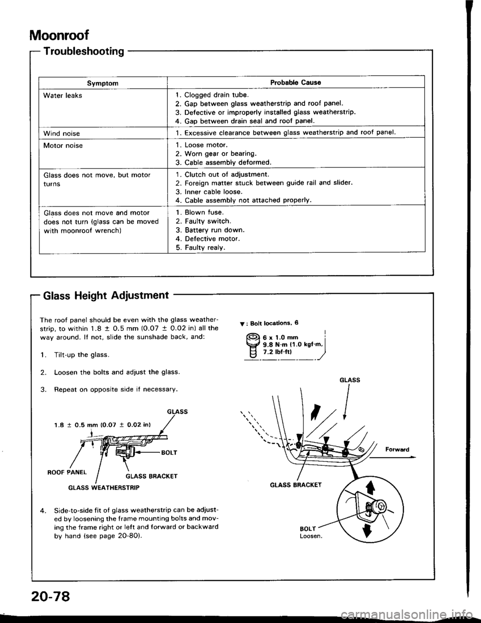
The roof panel should be even with the glass weather-
strip, to within l�8 t O.5 mm (O.O7 I 0.O2 in) all the
way around. It not, slide the sunshade back, and:
Y : Bolt locstions, 6
1.Tilt-up the glass.
Loosen the bolts and adjust the glass.
Repeat on opposite side it necessary.
2.
1.8 1 0.5 mm lO.O7 i0,O2 in)
i
ROOF PANELGLASS ERACKET
GLASS BRACKET
4.Side-to-side fit ot glass weatherstrip can be adjust-
ed by loosening the frame mounting bolts and mov-
ing the frame right or lelt and forward or backward
by hand (see page 2O-8O).
GLASS WEATI{ERSTRIP
f)
Glass Height Adiustment
20-78
Page 954 of 1413

SymptomProbable Cause
Water leaks1. Clogged drain tube.
2. Gap between glass weatherstrip and roof panel.
3. Defective or improperly installed glass weatherstrip.
4. Gap between drain seal and roof panel.
Wind noise1. Excessive clearance between glass weatherstrip and root panel.
Motor noise1. Loose motor.
2, Worn gear or bearing,
3. Cable assembly deformed.
Glass does not move, but motor
turns
1. Clutch out of adjustment.
2. Foreign matter stuck between guide rail and slider.
3. lnner cable loose.
4. Cable assembly not attached properly.
Glass does not move and motor
does not turn {glass can be moved
with moonroof wrench)
1. Blown fuse.
2. Faulty switch.
3, Battery run down.
4. Defective motor.
5. Faulty relay.
Glass Height Adjustment
The roof panel should be even with the glass weather-
strip, to within 1.8 tO.5mm{O.O7 1O.O2 in} allthe way
around. lf not, slide the sunshade back, and:
Tilt-up the glass.
Loosen the bolts and adjust the glass.
Repeat on opposite side if necessary.
ROOF PANELGLASS ERACKET
GLASS WEATHERSTRIP
4. Side-to-side fit of glass weatherstrip can be adjust-
ed by loosening the frame mounting bolts and mov-
ing the frame right or lett and forward or backward
by hand (see page 20-87).
GLASS BRACKETForward
V : Eolt localions, 6
6x LOmm9.8 N.m 11.O kgf m,7.2 tbf.ttt
I
")
1.
2.
GLASS
4'/1210.5 mm lO.O7 1O.02 inl
Page 986 of 1413
Seal b6lt buckle romoval:
1 . Remove the rear console (see page 20-128).
2. Slide the front seat until you can remove the screw.
then remove the center cover.
3. Oisconnect the connector (driver's), remove the
center anchor bolt, then remove the seat belt buckle.
> : Scrow locations, 2
CENTEB COVER
PLAIN WASHER
SEAT BELTBUCKLE
CONNECTOR
Upper and lower anchor bolt construction:
Hatchback
COLLARPLAINWASI{ER
iCENTER ANCHOR BOLT7/16-20 UNF32 N.m (3.3 ksf.m,7.2 lbf.ftl
LOCKWASHER
LOWER A CHORBOLTBEARING
lcont'd)
20-117
Page 987 of 1413
Front Seat Belt Replacement (cont'd)
Seat Belts
Sodan
.UPPER ANCHORBOLT
Canter anchor bolt consttuction:Rotractor bolt conslruction:
WAVE WASHER
Installation is the reverse ot the removal procedure.
NOTE:
a Make sure you assemble the washers and collars on the upper and lower anchor bolts as shown.
a Before attaching the side trim panel (Hatchbackl or center pillar lower trim (Sedan l. make sure the.e are no twists
or kinks in the front seat belt.
a On reassembly, replace the upper anchor bolt {Sedanl and center anchor bolt (*), and use liquid thread lock.
20-118
BEARING
Page 990 of 1413
Uppo. anchor bolt construction:
Hatchback
ANCHOR COVERUPPER ANCHOB
BEARING
COLLAR
Lower and cantol ancho. bolt conatluction:
LOWEB AI{CHOR BOLT/ANCHOR BOLT
Sedan
Rotracto. mounting bolt construclion:
RETRACTOR
LOCKWASHER
COLLAR
TOOTHEDLOCK WASHEN
TOOTHEDLOCK WASHER
TOOTHEDLOCK WASHER
TOOTHEOLOCK WASHER
UPPER AI{CHOR
WASHER
MOUNTING BOLT {Sedanl\/ /{- tr- J
l$t".,-,fu l-n(tYlf- u tY
\
Rotractor bolt construction:
RETRACTORAOLT
b'ryd
Installation is the reverse of the removal procedure.
NOTE:
a Make sure you assemble the washers and collars on the upper anchor bolt as shown.a Before attaching the side trim panel (Hatchbackl or rear shelf (Sedan), make sure there are no twists or kinksin the rear seat belt.
a Before attaching the seat-back, side bolsters {Sedan) and seat cushion, make sure there are no twisls or kinksin the rear seat belts.
a When instslling the seat cushion, slip the seat belt buckles through the slits in the seat cushion.
20-121
Page 1098 of 1413
Compressor
Glutch Inspection
Check the plated parts ot the pressure plate tor color
changes. peeling or other damage. lf there is dam-
8ge, replace the clutch set.
Check the pulley bearing play and drag by rotating
the pulley by hand. Replace the clutch set with a new
one if it is noisv or has excessive play/drag
Measure the clearance betlveen the pulley and the
pressure plate all the way around. lf the clearance is
not within specified limits, the pressure plate must be
removed and shims added or removed as required.
Jollowing the procedure on page 22-33.
Clearrnce: 0.50 t 0.15 mm {0.02 i 0.01 inl
NOTE: The shims are available in three thicknesses:
0.1 mm, 0.3 mm and 0.5 mm.
22-32
Check resistance of the tield coil.
Fisld Coil Rosistance: 3.6 t 0.2 ohm at 68"F {20'C)
lf resistance is not within specifications, replace the
field coil.
Page 1100 of 1413

and com
it with a
a
a
a
a
4t l\-N
r-
-l/
Compressor
Clutch Overhaul (cont'dl
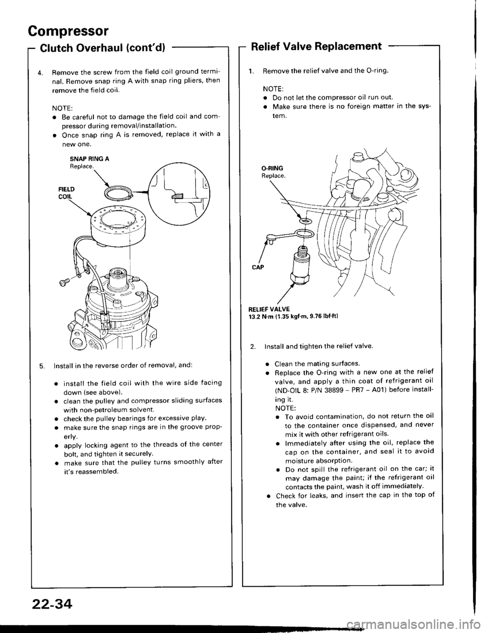
Remove the screw from the field coil ground terma-
nal. Remove snap ring A with snap rjng pliers, then
remove the field coil.
NOTE:
. Be careful not to damage the field coil
pressor during removal/installation.
. Once snap ring A is removed, replace
new one.
SNAP RING AReplace.
FIELDcorL
5. lnstall in the reverse order of removal, and:
install the field coil with the wire side facing
down (see above).
clean the pulley and compressor sliding surfaces
with non-petroleum solvent.
check the pulley bearings for excessive play.
make sure the snap rings are in the groove prop-
efly.
apply locking agent to the threads of the center
bolt, and tighten it securelY
make sure that the pulley turns smoothly after
it's reassembled.
1. Remove the relief valve and the O-ring.
NOTE:
. Do not let the compressor oil run out.
. Make sure there is no foreign matter in the sys-
tem.
RELIEF VALVE13.2 N.m {1.35 kgtm,9.76lbtftl
2. lnstall and tighten the relief valve.
Clean the mating surfaces.
Replace the O-ring with a new one at the relief
valve, and apply a thin coat of refrigerant oal
(ND-OIL 8: P/N 38899 - PR7 - A01) before install-
ing it.
NOTE:
. To avoid contamination, do not return the oil
to the container once dispensed, and never
mix it with other refrigerant oils.
. lmmediately after using the oil, replace the
cap on the container, and seal it to avoid
moisture absorption.
. Do not spill the refrigerant oil on the car; lt
may damage the painu if the refrigerant oil
contacts the paint, wash it off immediately.
Check for leaks, and insert the cap in the top of
the valve.
22-34
Page 1186 of 1413
![HONDA INTEGRA 1994 4.G Workshop Manual Starting
Startel
System
Overhaul
from clutch side.
-s@]
MOLYBDENUMDISULFIDE
CAUTION: Disconnecl th€ battery n€gative cable befole
lomoving the startet.
NOTE: The original radio has a coded theft p HONDA INTEGRA 1994 4.G Workshop Manual Starting
Startel
System
Overhaul
from clutch side.
-s@]
MOLYBDENUMDISULFIDE
CAUTION: Disconnecl th€ battery n€gative cable befole
lomoving the startet.
NOTE: The original radio has a coded theft p](/manual-img/13/6067/w960_6067-1185.png)
Starting
Startel
System
Overhaul
from clutch side.
-s@]
MOLYBDENUMDISULFIDE
CAUTION: Disconnecl th€ battery n€gative cable befole
lomoving the startet.
NOTE: The original radio has a coded theft protection
citcuit. Be sure to get the customer's code number before
- disconnecting the batterY.- removing the No.3 2 (7.5 A) fuse from the under-hood
fuse/relay box.- removing the tadio.
Atter service, reconnect power to the radio and turn at
on. When the word "CODE" is displayed, enter the cus-
tomer's 5-digit code to restore radio operation.
tr./.' BRUSH HOLDERTest, page 23-8'l
ERUSH
COVER
I
6
OVERRUNNING CLUTCH ASSEMBLYInspection, page 23_84
SOLENOIDPLUNGERInspection, page 23-85
BRUSH HOLOER
ARMATURE
STARTERSOLENOIDTest, page 23-78
PINION GEAR IDLER GEAR
Inspection, page 23-11
IDLER GEAR
I
@*
SOLENOID HOUSING
HARNESS BRACKET
STEEL BALL
install steel ball
lnspection and Test,page 23-82
ROLLER BEARINGSand CAGEPrevenl rollers trom being scattered and lost.
MOLYBDENUM DISULFIDE
_R1
MOLYADENUMDISULFIDE
23-80
ENO COVER
ARMATURE
GEAR HOUSING