Page 1207 of 1413
lFrom page 23-10O)'No. 24 (15 A): 818B'lNo. 24 (20 A): 818C1ongrneengine
Turn the ignition switch ott.
Check fuse *No. 24 in the under-dash tuse/relay bor.
Disconnect the 4-P connectorIrom the alternator.
Turn the ignition switch on {ll).
Ch6ck forvoltago between tho lGterminal (BLK/YEL wire) of rho il-Pconnector and body ground.
ls there battery voltage?Rgp.i. op.n in th. BLK|'EL wiro.
Ground the WHT/BLU wire at theL terminal ot the 4-P connector.
Chock for ! blown chrrging ry3-rom llghr bulb. It rh. butb i! oK,ropair open in lho IiYHT/BLU wiro.
Does the charging system lightcome on?
wirg sideL IWHT/BLUI
(cont'd)
23-101
Page 1209 of 1413
(From page 23-1021
Apply a load wirh the VA'-4O un-til the battery voltage drops to be-tween 12- 13.5 V.
ls the amperage 60 A or more?
With the engine spe6d still at2OOO rpm, full-tield the altemalor.
Toat rnd rooalr d|e dtomEtor {soopsg.. 23-104 to 23-tO7).
Turn the ignition switch off; thenturn at on again.
Disconnocl lhe 4-P connectorIrom the altornator.
Check lor voltage between the lGterminal (BLK/YEL) and bodyground.
ls there battery vokage?Rop.ii open in tho BLK/YEL wiro.
NOTE; Attach a probe to the VAT-4O full field test lead and insert the orobeinto the full tield sccess hole at the back of the alternator. Switch the field selectorto the "A (Ground)" position momentarily and check amperage reading.
CAUTION: The voltago will ris6 quickly whon the slternator is full-fiolded. Donot allow th€ voltago to oxc66d 18 V 01 it may damage the elect.ical system
REGULATOR
{Locatodthe end cover)
FULL FIELDACCESS HOLE
L IWHT/BLUI
4-P CONNECTOR
IG IBLKATELI
wire side
23-103
Page 1210 of 1413

Charging System
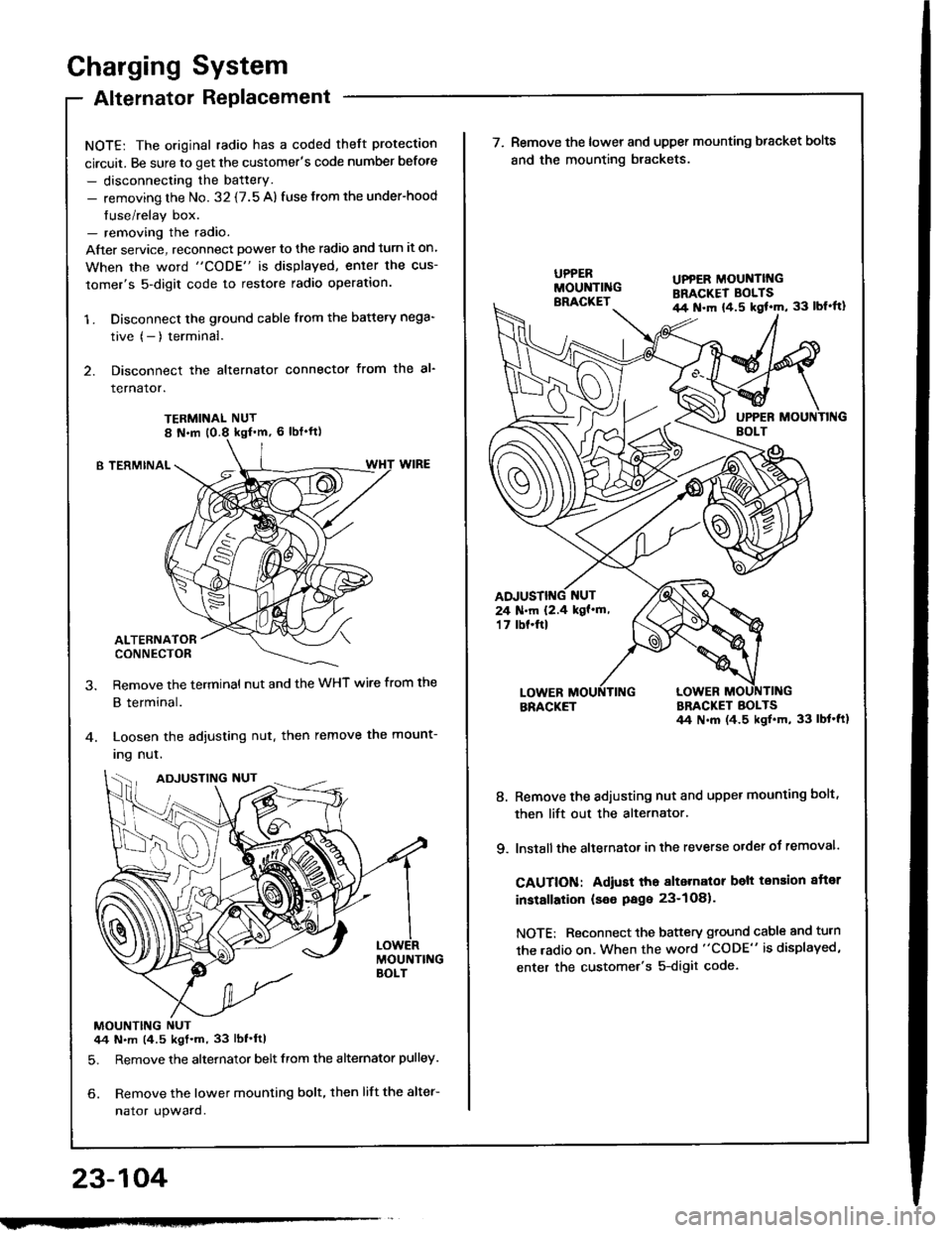
Alternator Replacement
NOTE: The original radio has a coded theft protection
circuit. Be sure to get the customer's code number before
- disconnecting the battery.- removing the No. 32 {7.5 A) fuse from the under-hood
fuse/relay box.- removing the radio.
After service, reconnect powet to the radio and turn it on.
When the word "CODE" is displayed, enler the cus-
tomer's 5-digit code to restore radio operation.
1 . Disconnect the ground cable from the battery nega-
tive (- ) terminal.
2. Disconnect the alternator connector from the al-
rernaror.
TERMINAL NUT
B TERMINAL
ALTERNATORCONNECTOR
Remove the terminal nut and the WHT wire from the
B terminal.
Loosen the adjusting nut. then remove the mount-
Ing nul.
MOUNTING NUT44 N.m (4.5 kgt.m, 33 lbf'ftl
5. Remove the alternator belt from the alternator pulley.
6. Remove the lower mounting bolt, then lift the alter-
nator upward.
23-104
ADJUSTING NUT
w
UPPER MOUNTII{GBRACKET BOLTSil4 N.m {4.5 kgl'm, 33 lbl'ft}
24 N.m 12.4 kgf'm,'t 7 tbf.ftl
\ (^,-(\
\-/ I
7. Remove the lower and upper mounting bracket bolts
and the mounting brackets.
BRACKETBRACKET BOLTS44 N.m (4.5 ksl.m, 33 lbt'ft1
8. Remove the adiusting nut and upper mounting bolt,
then lift out the alternator.
9. lnstall the altetnator in the reverse order of removal.
CAUTION: Adiust tho alternalor belt tension aftor
installation (seo Page 23-1O81.
NOTE: Reconnect the battery ground cable and turn
the radio on. When the word "CODE" is displayed,
enter the customer's 5-digit code.
Page 1218 of 1413
Fan Controls
Fan Motor Test
1. Disconnect the 2-P connector from the fan motor.
2. Test the motot by connecting battery power to the
B terminal, and ground to the A terminal
3. lf the Jan motor fails to run smoothly, replace it.
NOTE: The illustration shows the radiator fan.
Engine Coolant Temperature (ECT)
Switch Test
NOTE: Bleed air from the cooling system atter install-
ing the engine coolant temperature (ECT) switch (see sec-
tion 1O).
1. Remove the ECT switch from the thermostat
housing.
2. Suspend the ECT switch in a container of coolant
as shown.
Heat the coolant and check engine coolanl tempera-
ture with a thermometer.
Check the continuity between the A and B terminals
according to the table:
Terminal
;;,".,"---\
B
Switch
Above 196 2O3"F
{91-95'C)o_-o
Below 181- 189oF
(83-87'C)
23-112
Page 1219 of 1413
Gauge Assembly
Component Location Index
CAUTION:
a All SRS electrical wiring harnosses are cov€rod withyellow insulation.
a Bofore disconnecting any prn ot th€ SRS wire har-ness, connect tho short connector(sl.a R€place th6 entirs affGcted SRS halne$ assembly ifit has an open circuit o? damaged wiring.
SRS MAIN HARNESS{Cov.r6d with yollow inrularionl
GAUGE ASSEMBLYGauge Location Index, page 23-114Indicator Location Index, page 23-1 14Terminal Location Index, page 23-114Bulb Location. page 23-'l 15Disassembly. page 23-1 19Removal, page 23-118
FUEL GAUGE SENDING UNtTTest, page 23'124Repfacemenr, page 23-124
VEHICLE SPEEO SENSOB IVSS}Test, page 23-120fnput Test. page 23-120Repfacement, page 23-122
PARKITTG BRAKE SWITCHTest, page 23-127
BRAKE FLUID LEVEL SWITCHTesr, page 23-127
EI{GINE OIL PBESSURE SWITCHTest, page 23-122
ENGINE COOLANT TEMPERATURE IECTI GAUGESENOING UNITTest, page 23-126
(C61'ios tho SBS indicator signal)
23-113
Page 1220 of 1413
Gauge Assembly
Gauge/lndicator/Terminal Location Index
CAUTIOI{:
a All SRS olectrical wiring harnessos aro covorod with
yellow insulation,
Belol€ disconnecting any part ot tho SRS wiro hat-
nesa. connoct the short connoctol(El.
Replaco th6 entire aff6cted SRS hamess sssombly lf
it has an open circuil or damagod widng.
co r{EcroR "c" (c558}
FUEL GAUGE:Gauge Test, page 23-123
Sending Unit Tost, page 23-124
23,-114
A/T GEAR POSIT|OIIDICATOR SYSTEISee pags 23-132
E GI[{E COOLAI{T TEIIPEFATURE IECTIc6uge TEst, p6g6 23-126Sending Unit Tsst, pago 23-126
TACHOMETER:Indicatos lOO rpm at20O puls€s per minul€of the ignition controlmodul€ llCM).
SPEEDOMETER:Indicates (60 mph 6i 1025 rpml or{60 km/h at 637 rem) of th€v€hicle spe6d sonsor lVSSl.
CoNNECTOR "8" (c5601
Bi ----------+ B16Cl ----+ClO
f',. /i)
)Y
-"b
\_./ \J \-___--
a1 -----> A5
Dl-------.>D13
col{]{ECTOR "D" (C5591
rtrF --
coNNECfOR "A" (C557)
Page 1226 of 1413

Speedometer/Trip Meter/Odometer
Troubleshooting
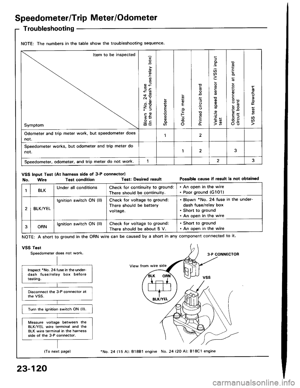
NOTE: The numbers in the table show the troubleshooting sequence.
Item to be inspected
Symptom
-9
;6+*c.r i.(D
zc*f
;59cd)=
E
a
6
E
'iF
o
(L
:lt)a
o
-9
>g
q)
qlv
E
'
E
oo
Odometer and trip meter wotk, but speedometer does
not.12
SDeedometer works, but odometer and trip meter do
nor,1
Speedometer. odometer, and trip meter do not work.
VSS Input Test (At ham€ss side of 3-P connector)
No. Wir6Tost conditionT€st: Desirsd resultPossible cause it result is not obtained
1BLKUnder all conditionsCheck for continuity to ground:
There should be continuity.
. An open in the wire. Poor ground (G1O1)
BLK/YEL
lgnition switch ON (ll)Check tor voltage to ground:
There should be battery
voltage.
Blown *No. 24 fuse in the unde.-
dash tus€/relay box
Short to ground
An open in the wire
ORNlgnition switch ON (ll)Check for voltage to ground:
There should be about 5 V.
. Shon to ground
. An open in the wire
NOTE: A short to ground in the
vSS Tost
Speedometer does not work.
ORN wire can be caused by a short in any component connected to lt.
3-P CONNECTOR
Inspect 'No. 24luse in the under-dash tuse/relay box beloretesting.
Turn the ignition switch ON lll).
Measure voltage between theBLK/YEL wire terminal and the8LK wire terminal in the harnessside of the 3-P connector.
{To next page)
23-120
24 (15 A): 81881 engine No. 24 {20 A): 818C1 engine
Page 1231 of 1413

Low FuelIndicator
IndicatorLight Test
Seat Belt Reminder
System
Seat Belt Switch Test
J.
NOTE: Reter to page 23- 1 1 6 tor the wiring description
of the low fuel indicator circuit.
1. Park car on level ground.
@ oo not rmoko whil6 working on th€
fuol system, Keop op€n llamg3 awsy from your work
area. Drain fuel only into an approvod container,
Drain tuel into an 8pplov€d container. Then install
the drain bolt with a new washer.
Add less than 8.2 t (2.2 U.S.Gal, 1.8 lmp.Gal) of fuel
and turn the ignition switch ON (ll). The low fuel in-
dicator light should com€ on within lour minutes,
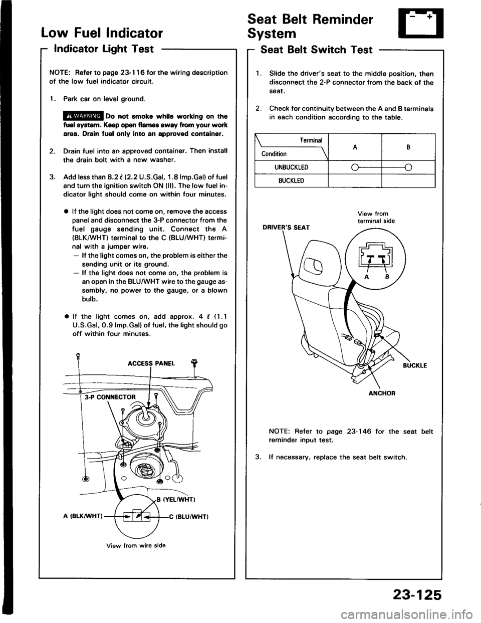
a lf the light does not come on, remove the access
Danel and disconnect the 3-P connector from the
fuel gauge sending unit, Connect the A
(BLKMHT) terminal to the C (BLU/WHT) termi-
nal with a iumper wir€.- lf the light comes on, the problem is either the
sending unit or its ground.- lf the light does not come on, the problem is
an open in the BLU/WHT wire to the gauge as-
sembly, no power to the gauge, or a blown
bulb.
a lf the light comes on, add approx. 4, {1.1
U.S.Gal, O.9lmp.Gal) ot tuel, the light should go
ofJ within four minutes.
3-P CONI{ECTOB
View lrom wire side
1.Slide the driver's seat to the middle position, then
disconnect the 2-P connector Jrom the back ot th€
sear.
Check for continuity between the A and B terminals
in each condition according to the table.
2.
NOTE: Befer to page 23-146 for the seat
reminder inout test.
3. lf necessary. replace the seat belt switch.
Terminal
C"** \AB
UNEUCKLEDo--o
BUCKLED
ANCHOR
23-125