Page 482 of 1413
Road Test
NOTE: Warm up the engine to operating temperature (the cooling fan comes on).
1 Apply parking brake and block th€ wheels. Start the engine, them move the selector lever to E] position whiledepressing the brake pedal. Depress the accelerator pedal, and release it suddenly. The engine should not stall,
2. Repeat same test in @ position.
3. Shift the selecto. lever to E position, and chock that the shift points occur at approximate speeds shown. Alsocheck fof abnormal noise and clutch slippage.
NOTE: Throttle position sensor voltage fepresents the throttle opening.
- 1 . Connect the Test Harness between the ECM and connector (see section 1 1).-2. Setthe digital multimeter to check voltage between D1 1{+)terminal and D22 { - ) terminal for the throttle Dosi-tion sensor.
TESTHARI{ESSOTLAJ_PT3OlOA
DIGITAL MULTIMETERCommarcially avsilablo o.KS-AHM-32-OO3
011 {+oooooooooooooooooooooooooooooooooooooooooooooooooooooooooooooooooooooooooooo
14-90
Page 557 of 1413

20. Connect the vehicle speed sensor (VSS), mainshatt
speed sensor and counterchalt speed sensor con
nectors.
VEHICLE SPEED SEiISORCONNECTOR
21. Connect the lock-uD control solenoid valve connec-
tor and shift control solenoid valve connector. then
clamp the lock-up control solenoid harness with the
harness stay.
22. Connect the transmission ground cable.
LOCK-UP CONTROLSOLENOID VALVE HARNESS STAY
23. Connect the starter cable to the starter motor, and
install the cable holder.
NOTE: When installing the starter motor cable,
make sure that the crimped side of the ring terminal
is facing out (see section 23).
CABLEHOLDER
6x 1.0 mm'12 N.m (1.2 kgf'm,8.7 lbt.tl)
24.
N.mlO.9 ksr.m, 7 tbr-rtt
STARTER CAELE
Install the air cleaner housing assembly and intake
arr oucl.
AIR CLEANER HOUSINGASSEMBLYINTAKE AIRDUCT
25.
26.
24.
29.
30.
Retill the transmission with ATF(see page '14-93).
Connect the battery positive ( + ) and negative ( - )
cables to the battery.
Start the engine. Set the parking brake, and shift the
transmission through all gears three times.
Check shitr cable adjustment as described on page
14-171 .
Check that front wheel alignment (see section 18).
Let the engine reach operating temperature (the cool-
ing tan comes on) with the transmission in S or @position, then turn it off and check the fluid level.
31. Road test as described on page 14-9o and 91.
14-167
Page 634 of 1413
5. Install the airbag assembly with new TORXo bolts.
TORXO BOLTS10 N.m {1.0 kgf'm.7 lbf ftl
Disconnect the short connector trom the airbag con-
nector.
Connect the airbag 3-P connector and cable reel 3-P
connector.
Attach the short connector on the access panel. and
install the access panel on the steering lower cover.
CABLE REEI-CONNECTOR
7.
YELLOW GEAR TOOTH
ALIGNMENT MARK
10.
Connect the battery positive terminal and th€n con-
nect the nsgative terminal.
After installing the sirbag assembly, confirm proper
system opera(on:
. Turn the ignition to ll: the instrum€nt pan6l SRS
indicator light should come on for about 6 sec-
onds and then go off,
. Confirm operation of horn buttons.
. Confirm oDeration of cruise control sevresume
switches.
a Turn the steering wheel countetclockwise and
make su.e the yellow gear tooth still lines up
with the alignment mark.
17-27
Page 1048 of 1413
Blower Motor
View from wire side
View from wire side
Blowor motor doos noi iun at all.
check the No. 37 (4o A) fuse intho under-hood fuse/relay box.
At th€ blower motor 2P connec-tor, connect the BLU/8LK wirc ter-minal to body ground wath ajumpe. wire.
Turn the ignition switch ON (ll).
Does the blower motor run?
Disconnect the blower motor 2Pconnector, and measure the vol-tago between the ELU/wHT wireterminal {+} and body ground
{-}.
Turn the ignition switch OFF.
Remove the blower motor relavfrom the under-hood fuse/relavbox and test it {see page 21-3O}.
Roplaco tho blowor motor rolay.
Measure the voltage betwgen theNo. 1 terminal (+) and bodyground (- ).
To page 21-12
To page 2l-13
"uf"'\'
,)
(cont'dl
21-11
Page 1051 of 1413
Troubleshooting
Mode Control Motor
21-14
Modo control motor dooa not nm,
or ono oa moto modo arc In_
oporgtivo.
Disconnect th6 mode control mo_
tor 8P connector.
Turn the ignition switch ON (ll).
Measuroth€ voltage b€tween tho
BLK/YEL wire terminal (+) and
bodv ground (- ).
R.p.lr op.n In lho BLrrYEL wl..
bctw.rn lha undard!.h fuaa/ru-
l.y box .nd ih. mod! corttol
motor.
Turn the ignition switch OFF.
To page 21-1 5
Page 1065 of 1413

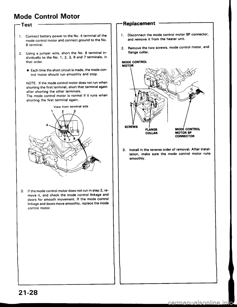
Mode Control Motor
Test
Connect batterY power to the No. 4 terminsl of the
mode control motor and connect ground to the No'
8 terminal.
Using a jumper wire, short the No. 8 terminsl in-
dividually to the No. 1, 2, 3. 6 and 7 terminals, in
that order.
a Each time the short circuit is mad€, the mode con-
trol motor should run smoothly and stop.
NOTE: ll the mode control motor does not run when
shorting the tirst terminsl, short that t€rminal again
after shorting the other terminals.
The mode control motor is no.mal it it runs when
shorting the tirst terminal again.
lf the mode control motor does not run in step 2, re'
move it, and check ths mode control linkage 8nd
doors for smooth movement. It the mod€ control
linkage and doors move smoothly, replace th€ mod€
control motor.
Disconnoct ths mode control motot 8P connector,
and remove it from lhe heater unit.
Remove the two sclsws, mode control motot, and
flango coll8,.
MODE CONTROLiioroR
3. lnst8ll in tho rsvsrse order of removal. After inst8l-
lstion, make sur€ the modo control motor runs
smoothlv.
Replacement
21-28
Page 1066 of 1413

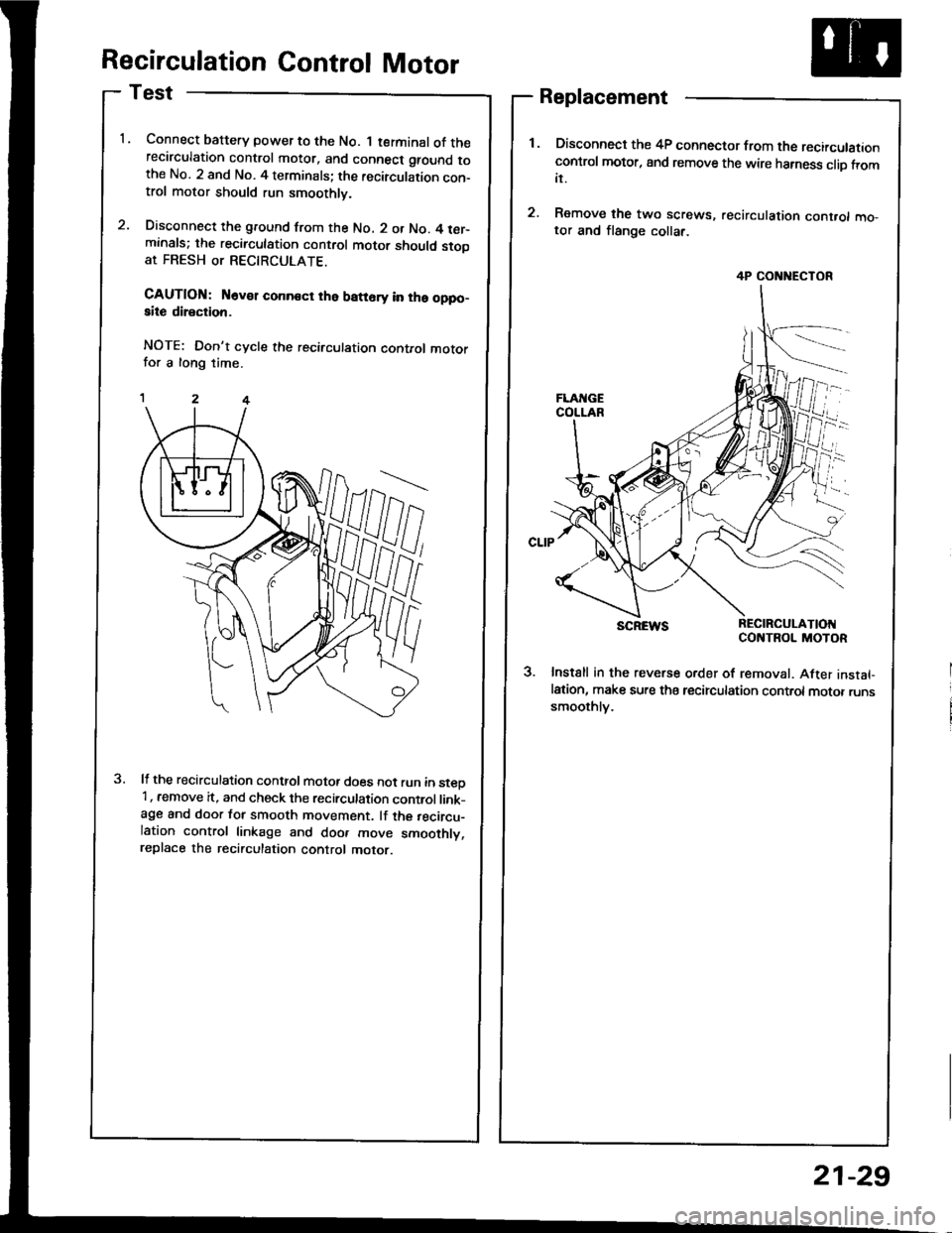
Recirculation Control Motor
Test
Connect baftery power to the No. 1 terminal of therecirculation control motor, and connect ground tothe No. 2 and No. 4 terminals; the recirculation con-trol motor should run smoothly.
Disconnect the ground from the No. 2 or No. 4 ter-minals; the recirculation control motor should stooat FRESH or RECTRCULATE.
CAUTION: N6v€r conn€ct the batt6ry in ths oppo-aite direction.
NOTE: Don't cycle the recirculation control motorfor a long time.
It the recirculation conttol motot does not run in steD'1, remove it, and check the recirculation control link-age and door for smooth movement. lf the recircu-lation control linkage and doo. move smoothly,replace the recirculation control motor.
Replacement
Disconnect the 4P connector from the recirculationcontrol motor, and remove the wire harness clio fromit.
Remove the two screws, recirculation cont.ol mo,tor and flange collar.
SCREWS REC|RCULAT|OIICONTROL MOTOR
3. Instsll in the reverse order of removal. After instal-lation, make sure tha tecirculation control motor runssmoothlv.
4P CONNECTOR
21-29
Page 1079 of 1413
From page 22-10
Disconnect the iumper wire andturn the ignition switch ON (ll).
Measure the voltage between theBLK/WHT wire terminal (+) andbody ground (-).
Reptir open in tha BLK/WHT o.BLK/YEL wire betwoon tho con-den3o. f.n rel.y and tho unde.-dash tus6/rel.y box.
Remove the iay'C diode from theAy'C diode 3P connector.
ls the A,/C diode OK?
Reprir op6n in th. BLU/YEL wirebetwocn tho conden3er tsn reltv.nd tho A/C diod€.
22-11