1994 HONDA INTEGRA connector or terminal
[x] Cancel search: connector or terminalPage 1084 of 1413
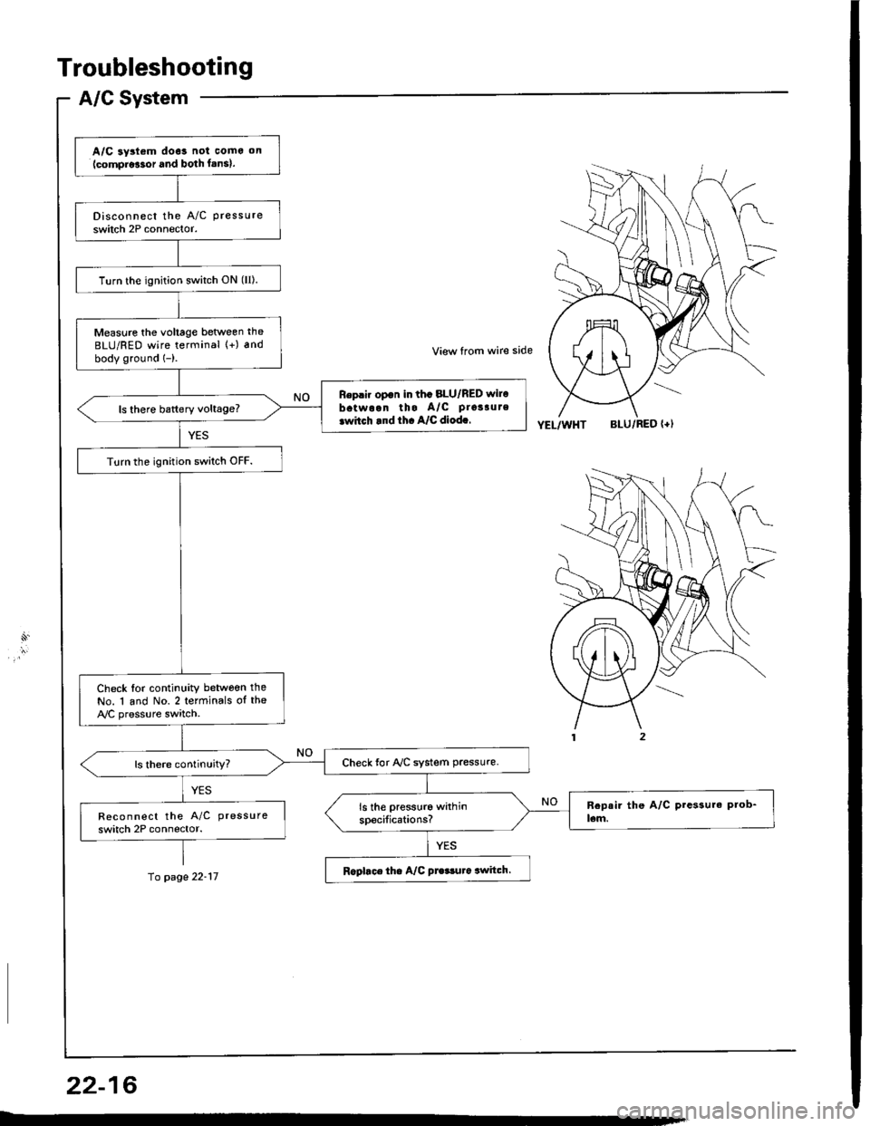
Troubleshooting
A/G System
10 page 22-17
A/C ay3t6m doe3 not como on(compro!3or and both f.ns).
Disconnect the A/C pressure
switch 2P connector.
Turn the ignition switch ON (II).
Measure the voltage beoveen the
BLU/RED wire terminal (+) and
bodv ground 1-).
Reprir opon in thc 8LU/RED wire
batwoan tho A/c prossute
rwitch rnd th. A/C diod..
Turn the ignition switch OFF.
Check lor continuity betwoen the
No. 1 and No. 2 terminals of the
A,/C pressure switch.
Check for NC system Pressure.
Reco n nect the A/C pressure
switch 2P connector.
Rophce tha A/C pre3!u.6 awitch.
View from wire side
YEL/WHTBLU/RED {+l
22-16
Page 1086 of 1413
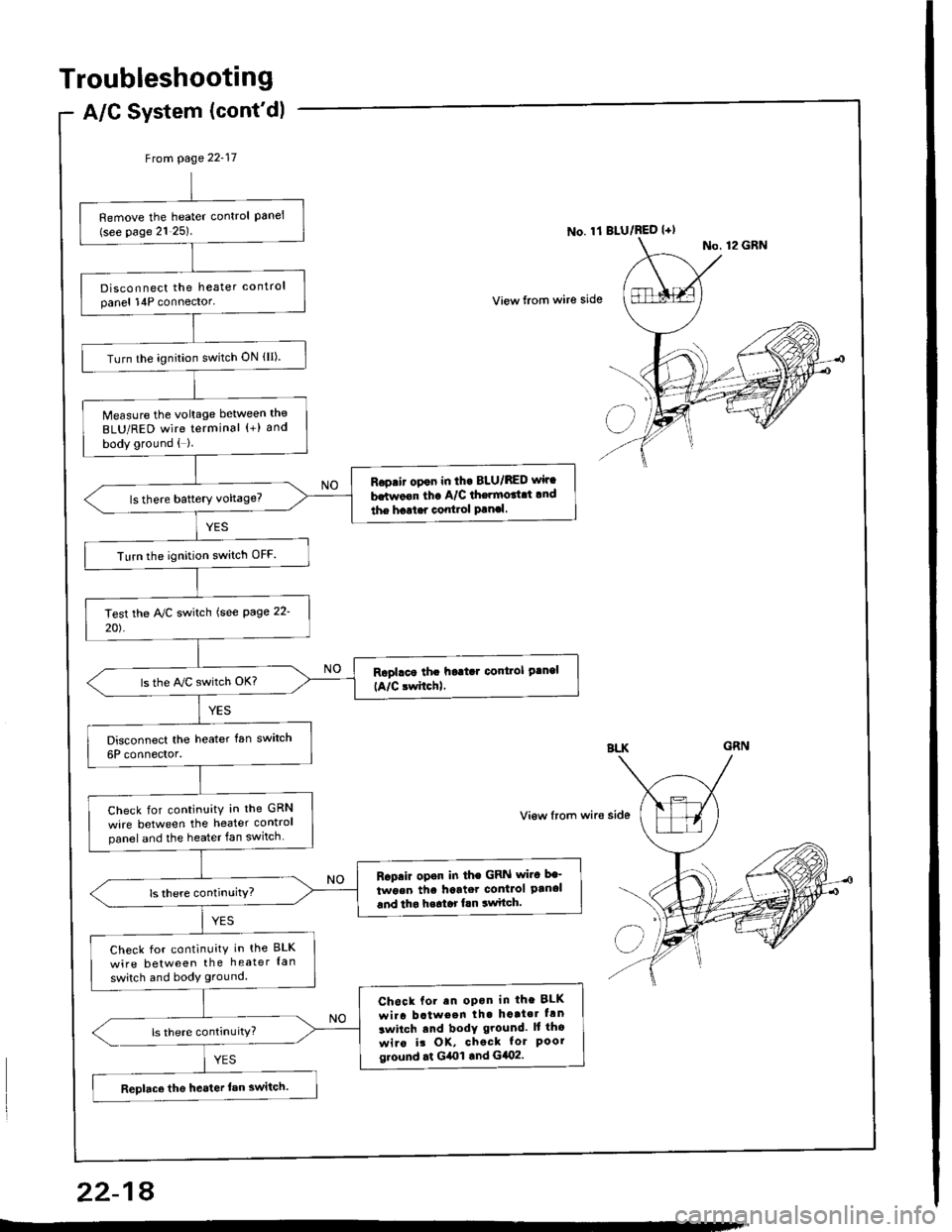
Troubleshooting
Remove the heater control Panel(see page 21 25)
Disconnect the heater controlpanel 14P connector'
Turn the ignition switch ON (lI).
Measure the voltage between the
BLU/RED wire terminal (+) and
body ground { }
Rop.i. opon in tho BLU/BED wir.
b.twoon tha A/C thermort.t lnd
the haat.r control Panal
Turn the ignition switch OFF.
ls the A/C switch OK?
Check for continuitY in the GRN
wire between the heater controlpanel and the heater fan switch
R.prir op.n in the GRN wiro be'
twoen thc hartet contlol Panaland tho h.rtor fln switch.
Check for continuity in the BLK
wire between the heater {an
switch and body ground.
Chock fol an opon in the BLK
wi.a b.tween th. hotte. hn
lwitch tnd bodY ground. ll tho
wiro it OK, chock for Poorg.ound .t G4ol .nd G402.
Replace the heater lan switch.
Frcm page 22'17
View lrom wire side
A/C System (cont'dl
No. 11 BLU/RED l+l
22-18
Page 1109 of 1413
Troubleshooting
Tips and Precautions
Before Troubloshooting
a Check applicable fuses in the appropriate fuse/relay
DOX.
a Check the battery for damage, state of charge, and
clean and tight connections.a Check the alternator belt tension.
CAUTION:
a Do not quick-charg€ a battery unless the batteryground cabla has be€n disconnoctsd. oth€rwisoyou will damage the alternator diodss.a Do not att6mpt to crank the engine with the bat-tery ground cable loosely connectsd or you will se-vorsly damag€ tho widng.
a The original radio has a codod thatt plotection ci.-cuit. Be sul€ to got tho customor's code numbet
before- disconnecting th€ battery.- lomoving tho No. 32 (7.5 Al tuso f.om the
under-hood tuse/lelay box.- removing tho radio.
Aflor s€lvic€. reconn€ct powet to tho radio and
turn it on. Whon the word "CODE" is displayed,
€nt€l the customer'E s-digit codo to .astore ladio
operation.
Handling Connectors
a Make sure the connectors are clean and have no loose
wire terminals.
a Make sure multiple cavity connectots are packed withgrease (except watertight connectors).a All connectors have push-down release type locks.
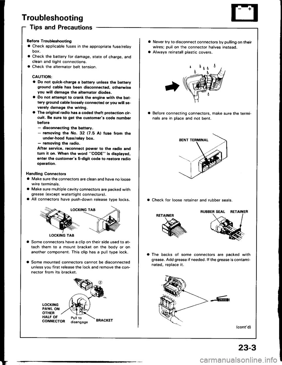
LOCKII{G TAA
LOCKING TAB
a Some connectors have a clio on their side used to at-
tach them to a mount bracket on the body or on
another component. This clip has a pull type lock.
a Some mounted connectors cannot be disconnected
unless you first release the lock and remove the con-
nector from its bracket.
LOCKINGPAWL ONOTHERHALF OFPull toorsengageCONNECTORBRACKET
23-3
a Never try to disconnect connectors by pulling on thei.
wires; pull on the connector halves instead.
a Always reinstall plastic covers.
Belore connecting connectors, make sure the lermi-
nals are in Dlace and not bent.
a Check tor loose retainer and rubber seals.
RETAINER
a The backs of some connectors are oacked with
grease. Add grease if needed. It the grease is contami-
nated, reDlace it.
(cont'd)
Page 1119 of 1413
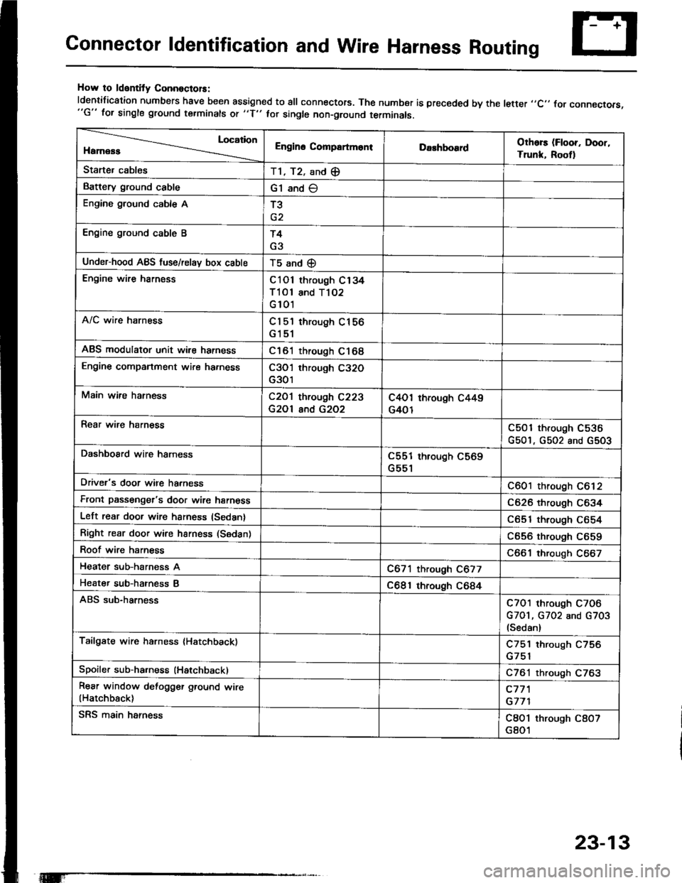
Connector ldentification and Wire Harness Routing
How to ldentity ConnoctolS:
ldentification numbers have been assigned to all connectors. The number is preceded by the letter ,,C,, for connecrors,"G" for single ground terminals ot "f" hr single non-ground terminals.
Location
HamessEngino CompartmontDarhboardOthors (Floor, Door,
Trunk, Rootl
Starter cablesT1, T2, and (E
Battery ground cableG1 and O
Engine ground cable AT3
Engine ground cable BT4
G3
Under-hood ABS fuse/relav box cableT5 and (D
Engine wire harnessC101 through C134
Tl Ol and T102
G 101
A/C wire harnessCl 5'l through C156
G151
ABS modulator unit wir€ harnessC161 through C168
Engine companment wire ha.nessC3O'l through C32O
G301
Main wire hatnessC2O1 through C223
G2Ol and G2O2
C4O1 through C449
G401
Rear wire harnessC501 through C536
G501, G502 and G5O3
DashboSrd wire harnessC551 through C569
G551
Driver's door wire harnessC601 through C612
Front passenger's door wire harnessC626 through C634
Left rear door wire harness (Sedan)C651 through C654
Right rear door wire harness (Sedan)C656 through C659
Roof wire harnessC661 through C667
Heater sub-harness AC671 through C677
Heater sub-hatness BC681 through C684
ABS sub-harnessC7O1 through C7O6
G7O1, G702 and G703(Sedan)
Tailgate wire harness (Hatchback)C751 through C756
Spoiler sub-ha.ness (Hatchback)C761 through C763
Rear window defogger ground wire(Hatchback)c77'l
G771
SRS main harnessC8O1 through C8O7
G801
23-13
Page 1120 of 1413
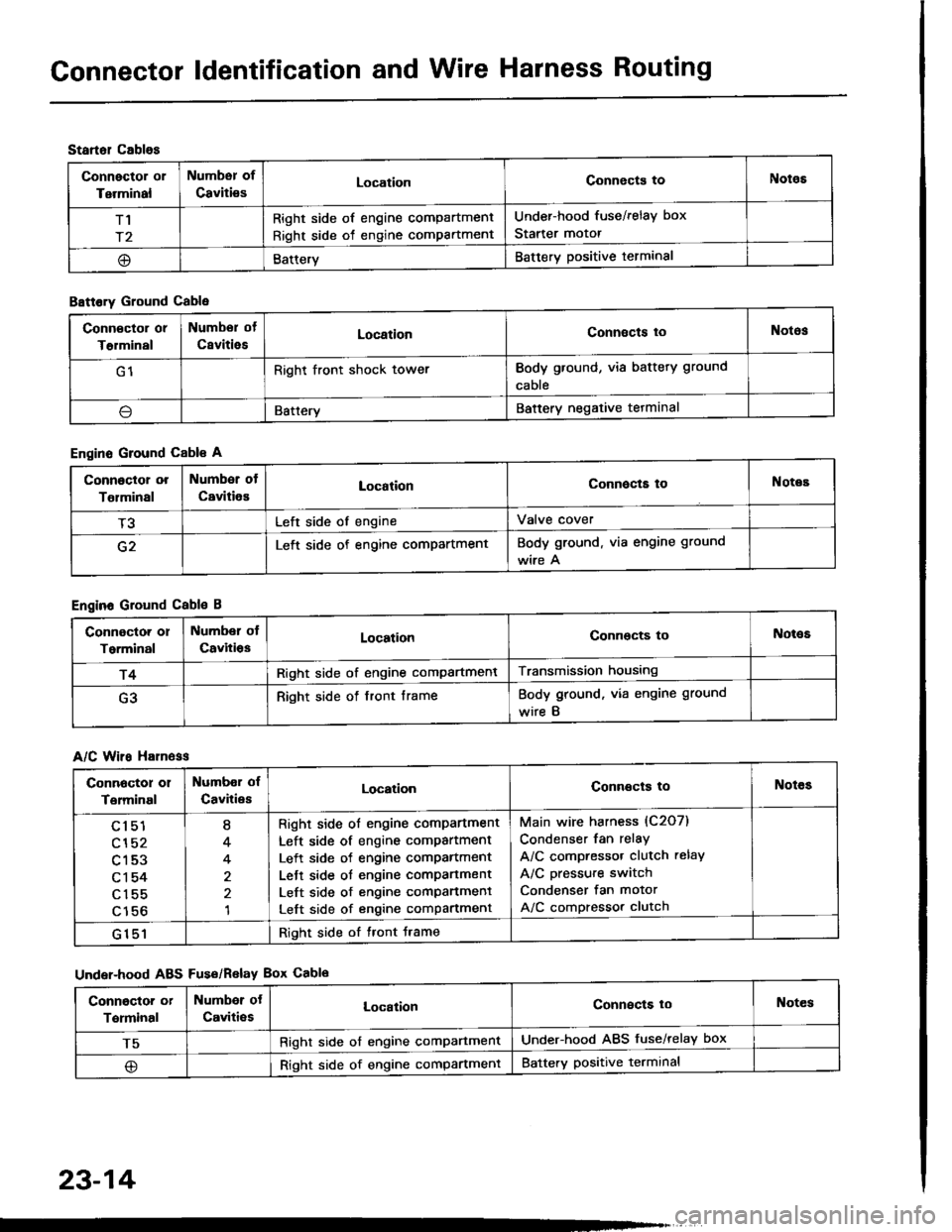
Gonnector ldentification and Wire Harness Routing
Startol cablos
Connector or
Terminal
Numbsr of
CavitiesLocationConnects toNotos
T1
r2
Right side of engine compartment
Right side of engine compartment
Under-hood fuse/relay box
Starter motor
@BatteryBattery positive terminal
B8ttory Ground Cable
Engine Ground Cable A
Engine Ground Cable B
A/C Wiro H81n6ss
Under-hood ABS Fus€/Relav Box Cablo
Conn€ctor or
T€rminal
Numbor of
CsvitiesLocationConnects toNotos
G1Right front shock towerBody ground, via battery ground
cable
\lBatteryBattery negative tetminal
Connoctor or
Tolminal
Number of
CavitiesLocationConnocta toNotes
T3Left side of engineValve cover
G2Left side of engine compartmentBody ground. via engine ground
wire A
Connoctor or
Torminal
Number ol
CavitiosLocationConnocts toNot€s
r4Right side of engine compartmentTransmission housing
G3Right side of front frameBody ground, via engine ground
wire B
Connoctor 01
Terminal
Numbor of
CavitiesLocationConnects toNotes
cl51
cl52
c153
c1 54
c155
c156
I
4
4
1
Right side ol engine comPartment
Left side of engine compartment
Left side of engine comPartment
Lett side ot engine compartment
Left side of engine comPanment
Left side of engine compartment
Main wire harness (C2O7)
Condenser fan relay
A/C compressor clutch relay
A/C pressure switch
Condenser fan motor
A/C compressor clutch
G151Right side of tront Jrame
Conngctor or
Terminal
Numbor ot
Caviti€sLocalionConnects loNotes
T5Right side of engine comPartmentUnder-hood ABS fuse/relay box
@Right side of engine compartmentBattery positive terminal
23-14
Page 1122 of 1413
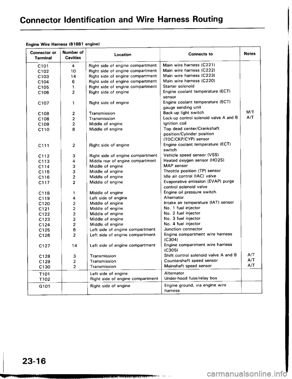
Gonnector ldentification and Wire Harness Routing
Engine Wire Harness {B1881engine)
Connector 01
Terminal
Number of
CavitiesLocationConnects ioNotes
c10'l
c102
c103
c104
c 105
c106
c107
c108
c108
c109
c110
c111
c113
c114
c115
Lt to
c117
c118
c119
c't 20
c121
c122
c123
cl24
c125
c't26
c127
c128
c129
c130
10
14
6
1
1
2
2
8
2
3
t
1
2
2)
2
8
14
2
2
Right side of engine compartment
Right side of engine compartment
Right side of engine compartment
Right side ol engine compartment
Right side of engine compartment
Right side of engine
Right side ol engine
Transmission
Transmission
Middle of engine
lvliddle of engine
Right side ot engine
Right side of engine compartment
ldiddle rear of engine compartment
Middle of engine
Middle ol engine
Middle of engine
Middle of engine
Middle ot engine
Left side of engine
lvliddle of engine
Middle of engine
Middle of engine
Middle ot engine
Middle ol engine
Left side of engine compartment
Left side of engine compartment
Left side of engine compartment
Transmission
Transmission
Transmission
Main wire harness (C221)
Main wire harness {C222}
Main wire harness (C223)
Main wire harness {C220)
Starter solenoid
Engine coolant temperature {ECT)
sensor
Engine coolant temperature (ECT)
gauge sending unit
Back'up light switch
Lock-up control solenoid valve A and B
lgnition coil
Top dead center/Crankshaft
position/Cylinder position
(TDC/CKP/CYP) sensor
Engine coolant temperature (ECT)
switch
Vehicle speed sensor (VSS)
Heated oxygen sensor (HO2S)
MAP sensor
Throttle position (TP) sensor
ldle air control (lAC) valve
Evaporative emission (EVAPI purge
control solenoid valve
Engine oil pressure switch
Alternator
Intake air temperature {lAT} sensor
No. 'l fuel injector
No. 2 tuel injector
No. 3 fuel injector
No. 4 fuel injector
Junction connector
Engine compartment wire harness
(c304)
Engine compartmenl wire harness
(c305)
Shift control solenoid valve A and B
Countershait speed sensor
Mainshaft speed sensor
M/T
NT
NT
NT
T 101
r102
Lelt side oI engine
Right side of engine compartment
Alternator
Under-hood tuse/relay box
G 101Right side of engineEngine ground, via engine wire
harness
23-16
Page 1130 of 1413
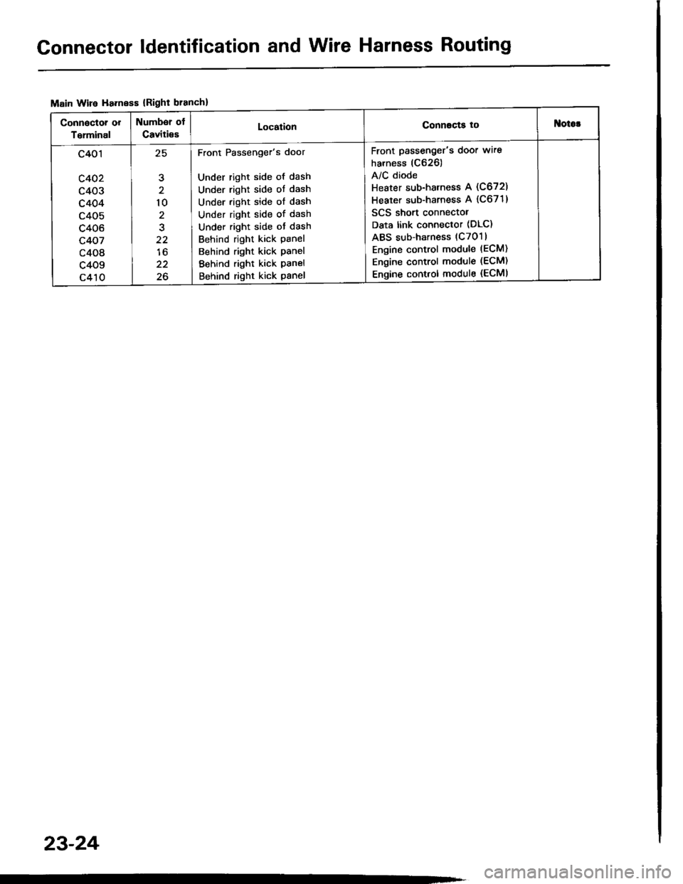
Connector ldentification and Wire Harness Routing
Main Wire Ha.ness {Right branch}
Connactor or
Terminal
Numbsr of
Caviti€sLocationConnscts tottlotor
c401
c402
c403
c404
c405
c406
c407
c408
c409
c410
,E
10
2
22
lo
22
26
Front Passenger's door
Under right side of dash
Under right side ot dash
Under right side of dash
Under right side of dash
Under right side ot dash
Behind right kick panel
Behind right kick panel
Behind right kick panel
Behind right kick panel
Front passenger's door wire
harness (C626)
A/C diode
Heater sub-harness A (C672)
Heater sub-harness A {C671}
SCS short connectol
Data link connector (DLC)
ABS sub-harness (C7011
Engine control module (ECM)
Engine control module (ECM)
Engine control module (ECMI
23-24
Page 1132 of 1413
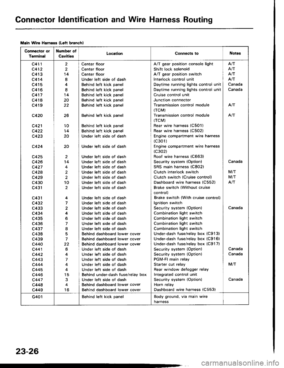
Connector ldentification and Wire Harness Routing
Msin Wiie Harness (Left branch)
Connector or
Terminal
Numbel ot
CavitiesLocationConnects toNotes
c411
c412
c413
c414
c415
c416
c4'17
c418
c419
c420
c42'l
c423
c424
c425
c426
c427
c42A
c429
c430
c431
c43l
c432
c433
c434
c435
c436
c437
c438
c439
c440
c44'l
c442
c443
c444
c445
c446
c447
c448
c449
26
10
20
20
14
8
4
I
14
20
22
't4
4
2
10
4
7
4
o
7
I
7
22
6
4
7
4
15
to
Center floor
Center floor
Center floor
Under left side ot dash
Behind left kick panel
Behind left kick panel
Behind left kick panel
Behind left kick panel
Behind left kick panel
Behind left kick panel
Behind left kick panel
Behind left kick panel
Under left side of dash
Under left side of dash
Under lett side of dash
Under left side ot dash
Under lett side of dash
Under lett side of dash
Under lett side of dash
Under lett side of dash
Under lett side ot dash
Under left side of dash
Under left side ol dash
Under left side of dash
Under left side of dash
Under left side of dash
Under left side of dash
Under left side of dash
Behind dashboard lower cover
Behind dashboard lower cover
Behind dashboard lower cover
Under left side of dash
Under left side of dash
Under left side of dash
Under lett side of dash
Under left side of dash
Behind under-dash fuse/relay box
Under left side ot dash
Behind dashboard lower cover
Behind dashboard lower cover
A/T gear position console light
Shift lock solenoid
A/T gear position switch
Interlock control unit
Daytime running lights control unit
Daytime running lights control unil
Cruise control unit
Junction connector
Transmission control module
(TCM)
Transmission controi module
{TCM)
Rear wire harness (C501)
Rear wire harness {C502)
Engine compartment wire harness
(c301)
Engine compartment wire harness
(c302)
Roof wire harness (C663)
Security system (Option)
SRS main harness (C802)
Clutch interlock switch
Clutch switch (Cruise control)
Dashboard wire harness (C552)
Brake switch (Without cruise
control)
Brake switch (With cruise control)
lgnition switch
Security system (Option)
Combination light switch
Combination light switch
Combination light switch
Combination light switch
Under-dash fuse/relay box {C9131
Under-dash fuse/relay box {C9161
Underdash tuse/relay box (C9'l 7l
Security system (Option)
Security system {Option)
PGM-FI main relay
Starter cut relay
Rear window defoqger relay
Integrated cont.ol unit
Security system {Option)
Horn relay
Dashboard wire harness (C553)
Afi
AiT
Afi
Afi
Canada
Canada
Arf
An
Canada
Canada
M/T
M/T
Atr
Canada
Canada
M/T
Canada
G401Behind left kick panelBody ground, via main wire
harness
23-26