1993 VOLKSWAGEN CORRADO sensor
[x] Cancel search: sensorPage 417 of 920

ANTI-LOCK BRAKE SYSTEM
Article Text (p. 7)
1993 Volkswagen Corrado
For Volkswagen Technical Site: http://vw.belcom.ru
Copyright © 1998 Mitchell Repair Information Company, LLC
Wednesday, March 22, 2000 08:57PM
connector terminals No. 9 and 10. See Fig. 2. If there is continuity,
switch is okay. If continuity does not exist, check wiring. If wiring
is okay, replace switch, and retest.
Right Rear Wheel Speed Sensor Resistance Test
Turn ignition off. Using an ohmmeter, measure resistance
between ECU connector terminals No. 4 and 22. See Fig. 2. If
resistance is 800-1400 ohms, go to next test. If resistance is not as
specified, check resistance at right rear wheel speed sensor. If
resistance is correct, repair wiring and retest. If resistance is not
correct, replace wheel speed sensor and retest.
Left Rear Wheel Speed Sensor Resistance Test
Using an ohmmeter, measure resistance between ECU connector
terminals No. 6 and 24. See Fig. 2. If resistance is 800-1400 ohms, go
to next test. If resistance is not as specified, check resistance at
left rear wheel speed sensor. If resistance is correct, repair wiring
and retest. If resistance is not correct, replace wheel speed sensor,
and retest.
Right Front Wheel Speed Sensor Resistance Test
Using an ohmmeter, measure resistance between ECU connector
terminals No. 7 and 25. See Fig. 2. If resistance is 800-1400 ohms, go
to next test. If resistance is not as specified, check resistance at
right front wheel speed sensor. If resistance is correct, repair
wiring and retest. If resistance is not correct, replace wheel speed
sensor and retest.
Left Front Wheel Speed Sensor Resistance Test
Using an ohmmeter, measure resistance between ECU connector
terminals No. 5 and 23. See Fig. 2. If resistance is 800-1400 ohms, go
to next test. If resistance is not as specified, check resistance at
left front wheel speed sensor. If resistance is correct, repair
wiring, and retest. If resistance is not correct, replace wheel speed
sensor, and retest.
Right Rear Wheel Speed Sensor Shielding Resistance Test
Using an ohmmeter, measure resistance between ECU connector
terminals No. 1 and 4. See Fig. 2. If resistance is 20,000 ohms or
more, go to next test. If resistance is less than 20,000 ohms, check
shielding wire for damage. Replace harness if damage is found and
retest.
Left Rear Wheel Speed Sensor Shielding Resistance Test
Using an ohmmeter, measure resistance between ECU connector
terminals No. 1 and 6. See Fig. 2. If resistance is 20,000 ohms or
more, go to next test. If resistance is less than 20,000 ohms, check
shielding wire for damage. Replace harness if damage is found and
retest.
Right Front Wheel Speed Sensor Shielding Resistance Test
Using an ohmmeter, measure resistance between ECU connector
Page 418 of 920
ANTI-LOCK BRAKE SYSTEM
Article Text (p. 8)
1993 Volkswagen Corrado
For Volkswagen Technical Site: http://vw.belcom.ru
Copyright © 1998 Mitchell Repair Information Company, LLC
Wednesday, March 22, 2000 08:57PM
terminals No. 1 and 7. See Fig. 2. If resistance is 20,000 ohms or
more, go to next test. If resistance is less than 20,000 ohms, check
shielding wire for damage. Replace harness if damaged, and retest.
Left Front Wheel Speed Sensor Shielding Resistance Test
Using an ohmmeter, measure resistance between ECU connector
terminals No. 1 and 5. See Fig. 2. If resistance is 20,000 ohms or
more, go to next test. If resistance is less than 20,000 ohms, check
shielding wire for damage. Replace harness if damaged, and retest.
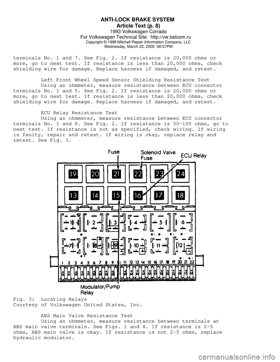
ECU Relay Resistance Test
Using an ohmmeter, measure resistance between ECU connector
terminals No. 1 and 8. See Fig. 2. If resistance is 50-100 ohms, go to
next test. If resistance is not as specified, check wiring. If wiring
is faulty, repair and retest. If wiring is okay, replace relay and
retest. See Fig. 3.Fig. 3: Locating Relays
Courtesy of Volkswagen United States, Inc.
ABS Main Valve Resistance Test
Using an ohmmeter, measure resistance between terminals at
ABS main valve terminals. See Figs. 1 and 4. If resistance is 2-5
ohms, ABS main valve is okay. If resistance is not 2-5 ohms, replace
hydraulic modulator.
Page 421 of 920

ANTI-LOCK BRAKE SYSTEM
Article Text (p. 11)
1993 Volkswagen Corrado
For Volkswagen Technical Site: http://vw.belcom.ru
Copyright © 1998 Mitchell Repair Information Company, LLC
Wednesday, March 22, 2000 08:57PM
Connect a jumper wire ECU between ECU connector terminals No.
2, 16 and 35. See Fig. 2. Depress brake pedal. Left front wheel should
be locked up. Turn ignition on. Left front wheel should rotate. If
wheel does not rotate, replace hydraulic modulator. Turn ignition off.
REMOVAL & INSTALLATION
HYDRAULIC MODULATOR/PUMP
Removal & Installation
1) Depressurize brake system. See DEPRESSURIZING BRAKE
SYSTEM. Disconnect negative battery cable. Unplug all electrical
connectors from hydraulic modulator/pump. Identify and disconnect all
hydraulic lines from hydraulic modulator/pump. Plug all line openings.
2) From inside passenger compartment, remove push rod clevis
pin. Remove hydraulic modulator/pump retaining nuts. Remove hydraulic
modulator/pump. To install, reverse removal procedure. Tighten all
fittings to specification. See TORQUE SPECIFICATIONS table. Bleed
brake system. See BLEEDING BRAKE SYSTEM.
WHEEL SPEED SENSORS
NOTE: To protect magnetic part of sensor, always leave new wheel
speed sensor in special packaging until ready for
installation.
Removal & Installation
Remove bolt retaining wheel speed sensor. Unplug connector.
Remove wheel speed sensor. To install, apply Lubricant (G-000-650) to
sensor. Install sensor, and tighten retaining bolt to 84 INCH lbs. (10
N.m).
TORQUE SPECIFICATIONS
TORQUE SPECIFICATIONS TABLEÄÄÄÄÄÄÄÄÄÄÄÄÄÄÄÄÄÄÄÄÄÄÄÄÄÄÄÄÄÄÄÄÄÄÄÄÄÄÄÄÄÄÄÄÄÄÄÄÄÄÄÄÄÄÄÄÄÄÄÄÄÄÄÄÄÄÄÄÄÄApplications Ft. Lbs. (N.m)
Brake Lines-To-Hydraulic Modulator/Pump .................... 11 (15)
Hydraulic Modulator/Pump Retaining Nuts .................... 18 (25)
INCH Lbs. (N.m)
Wheel Sensor Retaining Bolt ................................ 89 (10)
ÄÄÄÄÄÄÄÄÄÄÄÄÄÄÄÄÄÄÄÄÄÄÄÄÄÄÄÄÄÄÄÄÄÄÄÄÄÄÄÄÄÄÄÄÄÄÄÄÄÄÄÄÄÄÄÄÄÄÄÄÄÄÄÄÄÄÄÄÄÄ WIRING DIAGRAMS
Page 431 of 920

B - EMISSION APPLICATION
Article Text (p. 2)
1993 Volkswagen Corrado
For Volkswagen Technical Site: http://vw.belcom.ru
Copyright © 1998 Mitchell Repair Information Company, LLC
Wednesday, March 22, 2000 08:57PM
2.0L 4-Cyl. CIS-E Motronic
Major Control Systems & Devices ............. PCV, EVAP, TWC, FR,
(2) EGR, SPK, AP,
(1) O2, CEC, (2) MIL
Components & Other Related Devices ........ (4) EVAP-PV, EVAP-CV,
EGR-VA, EGR-TVV, SPK-CC
2.8L VR6 Motronic MFI
Major Control Systems & Devices ........ PCV, EVAP, TWC, FR, EGR,
SPK, AP, (1) O2, CEC, (2) MIL
Components & Other Related Devices ...... AP-EAP, AP-ERLY, AP-SV,
AP-SOV, EVAP-PV, EVAP-VC,
EGR-CV, EGR-TS, SPK-CC
(1) - Heated O2 sensor.
(2) - California only.
(3) - Digifant II only.
(4) - Two required.ÄÄÄÄÄÄÄÄÄÄÄÄÄÄÄÄÄÄÄÄÄÄÄÄÄÄÄÄÄÄÄÄÄÄÄÄÄÄÄÄÄÄÄÄÄÄÄÄÄÄÄÄÄÄÄÄÄÄÄÄÄÄÄÄÄÄÄÄÄÄ ABBREVIATION DEFINITIONS
ABBREVIATION DEFINITION TABLE
ÄÄÄÄÄÄÄÄÄÄÄÄÄÄÄÄÄÄÄÄÄÄÄÄÄÄÄÄÄÄÄÄÄÄÄÄÄÄÄÄÄÄÄÄÄÄÄÄÄÄÄÄÄÄÄÄÄÄÄÄAbbreviation Definition
AP ............................. Air Pump Injection System
AP-EAP .............................. AP Electric Air Pump
AP-ERLY ....................... AP Electric Air Pump Relay
AP-SV .......................... AP Solenoid (Inlet) Valve
AP-SOV ................................. AP Shut Off Valve
CEC ......................... Computerized Engine Controls
EGR ............................ Exhaust Gas Recirculation
EGR-CV ..................... EGR Control (Frequency) Valve
EGR-TS ............................ EGR Temperature Sensor
EGR-TVV ......................... EGR Thermal Vacuum Valve
EGR-VA .............................. EGR Vacuum Amplifier
EVAP ............................. Fuel Evaporative System
EVAP-CS ............................ EVAP Control Solenoid
EVAP-PV ................................. EVAP Purge Valve
EVAP-VC .............................. EVAP Vapor Canister
FR .................................. Fill Pipe Restrictor
HAI ....................................... Hot Air Intake
MIL ........... Malfunction Indicator (CHECK ENGINE) Light
MFI ............................. Multiport Fuel Injection
O2 ......................................... Oxygen Sensor
PCV ....................... Positive Crankcase Ventilation
SPK ................................. Spark Control System
SPK-CC ........................... SPK Computer Controlled
TWC ................................... Three-Way Catalyst
ÄÄÄÄÄÄÄÄÄÄÄÄÄÄÄÄÄÄÄÄÄÄÄÄÄÄÄÄÄÄÄÄÄÄÄÄÄÄÄÄÄÄÄÄÄÄÄÄÄÄÄÄÄÄÄÄÄÄÄÄEND OF ARTICLE
Page 479 of 920
ELECTRICAL COMPONENT LOCATOR
Article Text (p. 21)
1993 Volkswagen Corrado
For Volkswagen Technical Site: http://vw.belcom.ru
Copyright © 1998 Mitchell Repair Information Company, LLC
Wednesday, March 22, 2000 09:09PM
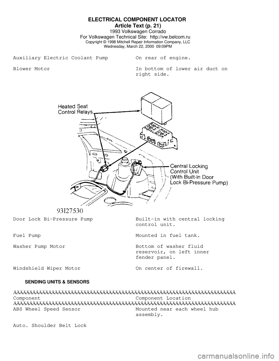
Auxiliary Electric Coolant Pump On rear of engine.
Blower Motor In bottom of lower air duct on
right side.Door Lock Bi-Pressure Pump Built-in with central locking
control unit.
Fuel Pump Mounted in fuel tank.
Washer Pump Motor Bottom of washer fluid
reservoir, on left inner
fender panel.
Windshield Wiper Motor On center of firewall.
SENDING UNITS & SENSORSÄÄÄÄÄÄÄÄÄÄÄÄÄÄÄÄÄÄÄÄÄÄÄÄÄÄÄÄÄÄÄÄÄÄÄÄÄÄÄÄÄÄÄÄÄÄÄÄÄÄÄÄÄÄÄÄÄÄÄÄÄÄÄÄÄÄÄÄÄÄComponent Component Location
ÄÄÄÄÄÄÄÄÄÄÄÄÄÄÄÄÄÄÄÄÄÄÄÄÄÄÄÄÄÄÄÄÄÄÄÄÄÄÄÄÄÄÄÄÄÄÄÄÄÄÄÄÄÄÄÄÄÄÄÄÄÄÄÄÄÄÄÄÄÄABS Wheel Speed Sensor Mounted near each wheel hub
assembly.
Auto. Shoulder Belt Lock
Page 480 of 920
ELECTRICAL COMPONENT LOCATOR
Article Text (p. 22)
1993 Volkswagen Corrado
For Volkswagen Technical Site: http://vw.belcom.ru
Copyright © 1998 Mitchell Repair Information Company, LLC
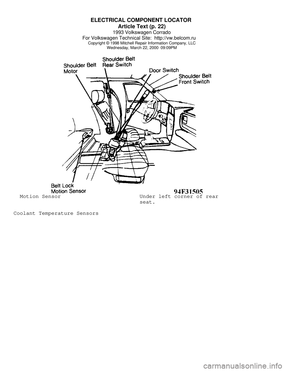
Wednesday, March 22, 2000 09:09PM Motion Sensor Under left corner of rear
seat.
Coolant Temperature Sensors
Page 483 of 920
ELECTRICAL COMPONENT LOCATOR
Article Text (p. 25)
1993 Volkswagen Corrado
For Volkswagen Technical Site: http://vw.belcom.ru
Copyright © 1998 Mitchell Repair Information Company, LLC
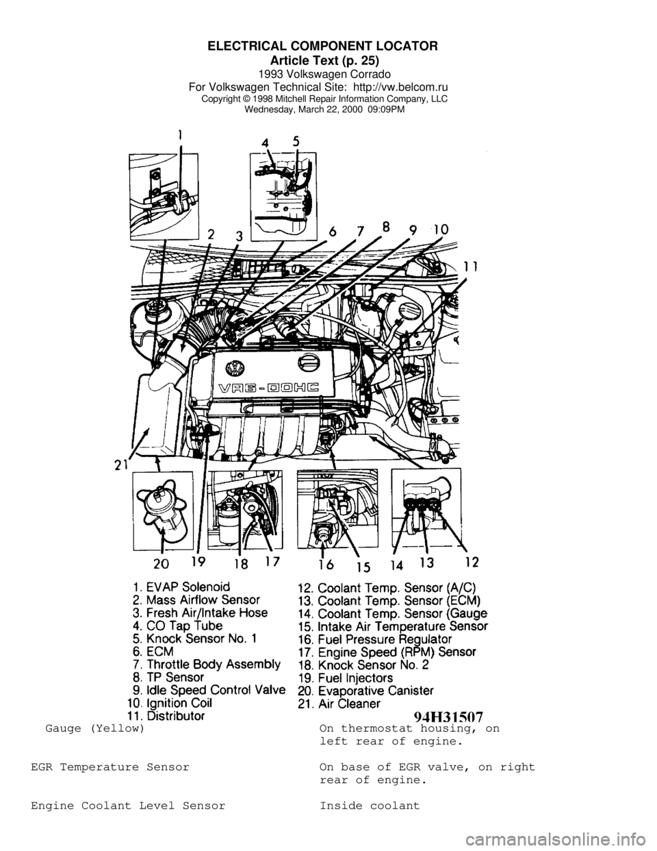
Wednesday, March 22, 2000 09:09PM Gauge (Yellow) On thermostat housing, on
left rear of engine.
EGR Temperature Sensor On base of EGR valve, on right
rear of engine.
Engine Coolant Level Sensor Inside coolant
Page 484 of 920
ELECTRICAL COMPONENT LOCATOR
Article Text (p. 26)
1993 Volkswagen Corrado
For Volkswagen Technical Site: http://vw.belcom.ru
Copyright © 1998 Mitchell Repair Information Company, LLC
Wednesday, March 22, 2000 09:09PM
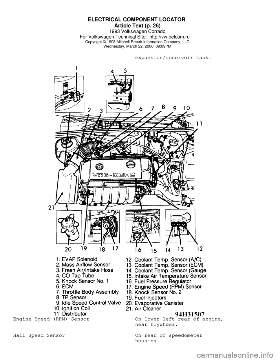
expansion/reservoir tank.Engine Speed (RPM) Sensor On lower left rear of engine,
near flywheel.
Hall Speed Sensor On rear of speedometer
housing.