1993 FORD MONDEO change
[x] Cancel search: changePage 88 of 279
rod’s big-end onto the crankpin. The piston
rings may try to pop out of the ring
compressor just before entering the cylinder
bore, so keep some pressure on the ring
compressor. Work slowly, and if any
resistance is felt as the piston enters the
cylinder, stop immediately. Find out what’s
binding, and fix it before proceeding. Do not,
for any reason, force the piston into the
cylinder - you might break a ring and/or the
piston.
10To check the big-end bearing running
clearance, cut a piece of the appropriate-size
Plastigage slightly shorter than the width of
the connecting rod bearing, and lay it in place
on the No 1 crankpin (big-end) journal, parallel
with the crankshaft centre-line (see illus-
tration 17.6).
11Clean the connecting rod-to-cap mating
surfaces, and refit the big-end bearing cap.
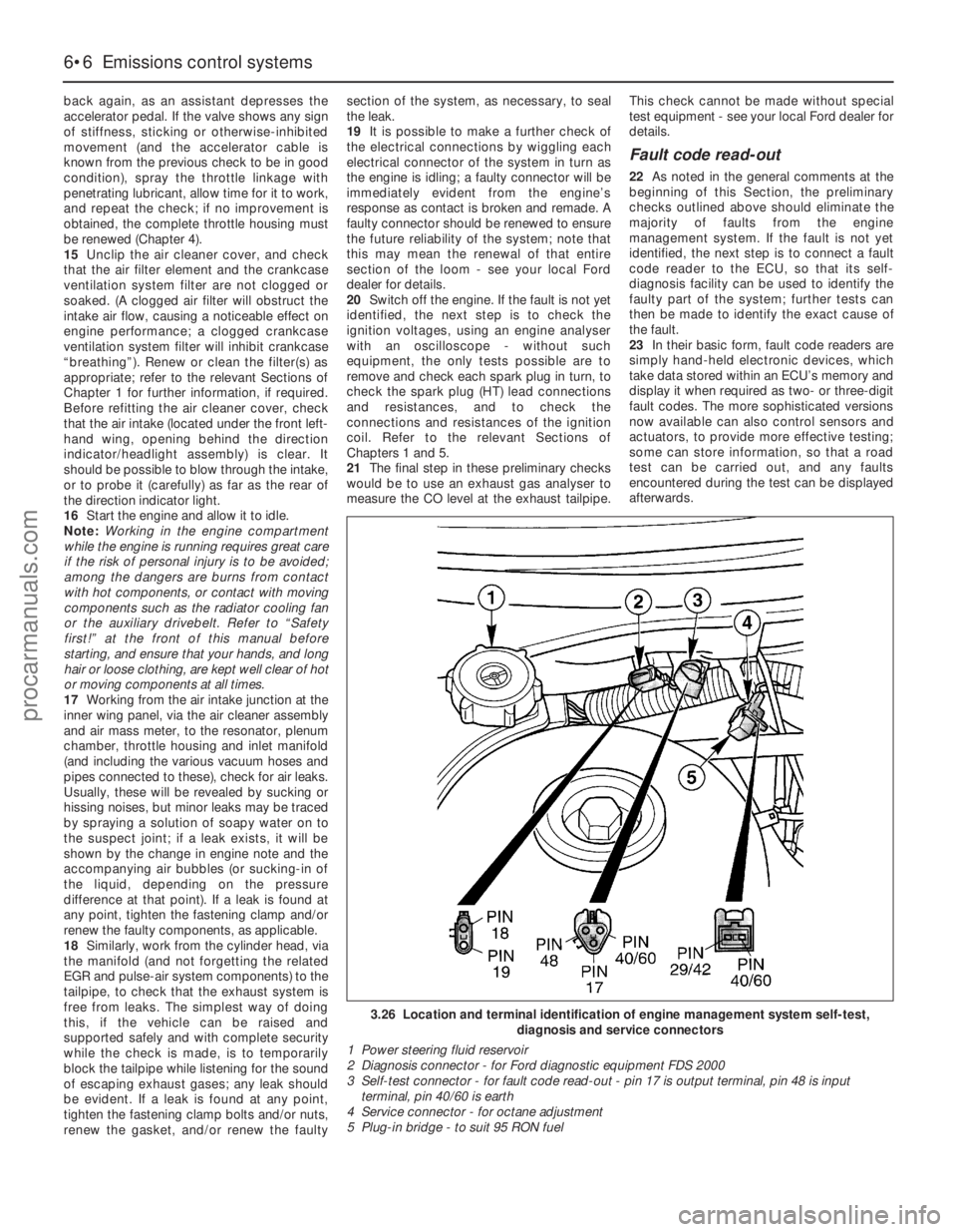
Make sure the etched number on the cap is
on the same side as that on the rod (see
illustration). Tighten the cap bolts evenly -
first use a torque wrench to tighten the bolts
to the specified (first stage) torque setting,
then use an ordinary socket extension bar
and an angle gauge to tighten the bolts
further through the specified (second stage)
angle. Use a thin-wall socket, to avoid
erroneous torque readings that can result if
the socket is wedged between the cap and
nut. If the socket tends to wedge itself
between the nut and the cap, lift up on it
slightly until it no longer contacts the cap.
Don’t rotate the crankshaft at any time during
this operation!
12Unscrew the bolts and detach the cap,
being very careful not to disturb the
Plastigage.
13Compare the width of the crushed
Plastigage to the scale printed on the
Plastigage envelope, to obtain the running
clearance (see illustration 17.10). Compare it
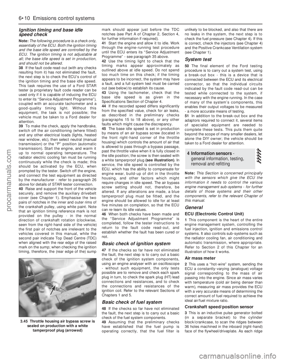
to the Specifications, to make sure the
clearance is correct.
14If the clearance is not as specified, seek
the advice of a Ford dealer or similar engine
reconditioning specialist - if the crankshaft
journals are in good condition (see Sec-
tion 13), it may be possible simply to renew
the shells to achieve the correct clearance. If
this is not possible, the crankshaft must bereground by a specialist, who can also supply
the necessary undersized shells. First though,
make sure that no dirt or oil was trapped
between the bearing shells and the
connecting rod or cap when the clearance
was measured. Also, recheck the crankpin
diameter. If the Plastigage was wider at one
end than the other, the crankpin journal may
be tapered (see Section 13).
15Carefully scrape all traces of the
Plastigage material off the journal and the
bearing surface. Be very careful not to scratch
the bearing - use your fingernail or the edge of
a credit card.
Final piston/connecting rod
refitting
16Make sure the bearing surfaces are
perfectly clean, then apply a uniform layer of
clean molybdenum disulphide-based grease,
engine assembly lubricant, or clean engine oil,
to both of them. You’ll have to push the piston
into the cylinder to expose the bearing surface
of the shell in the connecting rod.
17Slide the connecting rod back into place
on the crankpin (big-end) journal, refit the big-
end bearing cap, and then tighten the bolts in
two stages, as described above.
18Repeat the entire procedure for the
remaining piston/connecting rod assemblies.
19The important points to remember are:
(a) Keep the backs of the bearing shells and
the recesses of the connecting rods and
caps perfectly clean when assembling
them.
(b) Make sure you have the correct
piston/rod assembly for each cylinder -
use the etched cylinder numbers to
identify the front-facing side of both the
rod and its cap.
(c) The arrow on the piston crown must face
the timing belt end of the engine.
(d) Lubricate the cylinder bores with clean
engine oil.
(e) Lubricate the bearing surfaces when
refitting the big-end bearing caps after the
running clearance has been checked.
20After all the piston/connecting rod
assemblies have been properly installed,
rotate the crankshaft a number of times by
hand, to check for any obvious binding.1With the engine refitted in the vehicle,
double-check the engine oil and coolant
levels. Make a final check that everything has
been reconnected, and that there are no tools
or rags left in the engine compartment.
2With the spark plugs removed and the
ignition system disabled by unplugging the
ignition coil’s electrical connector, remove
fuse 14 to disconnect the fuel pump. Turn the
engine on the starter until the oil pressure
warning light goes out.
3Refit the spark plugs, and connect all the
spark plug (HT) leads (Chapter 1). Reconnect
the ignition coil wiring, refit the fuel pump fuse,
then switch on the ignition and listen for the fuel
pump; it will run for a little longer than usual,
due to the lack of pressure in the system.
4Start the engine, noting that this also may
take a little longer than usual, due to the fuel
system components being empty.
5While the engine is idling, check for fuel,
coolant and oil leaks. Don’t be alarmed if
there are some odd smells and smoke from
parts getting hot and burning off oil deposits.
If the hydraulic tappets have been disturbed,
some valve gear noise may be heard at first;
this should disappear as the oil circulates fully
around the engine, and normal pressure is
restored in the tappets.
6Keep the engine idling until hot water is felt
circulating through the top hose, check that it
idles reasonably smoothly and at the usual
speed, then switch it off.
7After a few minutes, recheck the oil and
coolant levels, and top-up as necessary
(Chapter 1).
8If they were tightened as described, there is
no need to re-tighten the cylinder head bolts
once the engine has first run after reassembly
- in fact, Ford state that the bolts must notbe
re-tightened.
9If new components such as pistons, rings
or crankshaft bearings have been fitted, the
engine must be run-in for the first 500 miles
(800 km). Do not operate the engine at full-
throttle, or allow it to labour in any gear during
this period. It is recommended that the oil and
filter be changed at the end of this period.
19 Engine -
initial start-up after overhaul
2B•22 Engine removal and general engine overhaul procedures
procarmanuals.com
Page 136 of 279
To minimise pollution of the atmosphere
from incompletely-burned and evaporating
gases, and to maintain good driveability and
fuel economy, a number of emission control
systems are used on these vehicles. They
include the following:
(a) The engine management system
(comprising both fuel and ignition sub-
systems) itself.
(b) Positive Crankcase Ventilation (PCV)
system.
(c) Evaporative Emissions Control (EVAP)
system.
(d) Exhaust Gas Recirculation (EGR) system.
(e) Catalytic converter.
The Sections of this Chapter include
general descriptions, checking procedures
within the scope of the home mechanic, and
component renewal procedures (when
possible) for each of the systems listed above.
Before assuming an emissions control system
is malfunctioning, check the fuel and ignition
systems carefully (see Chapters 4 and 5). The
diagnosis of some emission control devices
requires specialised tools, equipment and
training. If checking and servicing become too
difficult, or if a procedure is beyond the scope ofyour skills, consult your dealer service
department or other specialist.
This doesn’t mean, however, that emission
control systems are particularly difficult to
maintain and repair. You can quickly and
easily perform many checks, and do most of
the regular maintenance, at home with
common tune-up and hand tools. Note:The
most frequent cause of emissions problems is
simply a loose or broken electrical connector
or vacuum hose, so always check the
electrical connectors and vacuum hoses first.
Pay close attention to any special
precautions outlined in this Chapter. It should
be noted that the illustrations of the various
systems may not exactly match the system
installed on your vehicle, due to changes
made by the manufacturer during production
or from year-to-year.
Vehicles sold in some areas will carry a
Vehicle Emissions Control Information (VECI)
label, and a vacuum hose diagram located in
the engine compartment. These contain
important specifications and setting
procedures for the various emissions control
systems, with the vacuum hose diagram
identifying emissions control components.
When servicing the engine or emissions
systems, the VECI label in your particular
vehicle should always be checked for up-to-
date information.Description
The EEC-IV (Ford’s fourth-generation
Electronic Engine Control system) engine
management system controls fuel injection by
means of a microcomputer known as the ECU
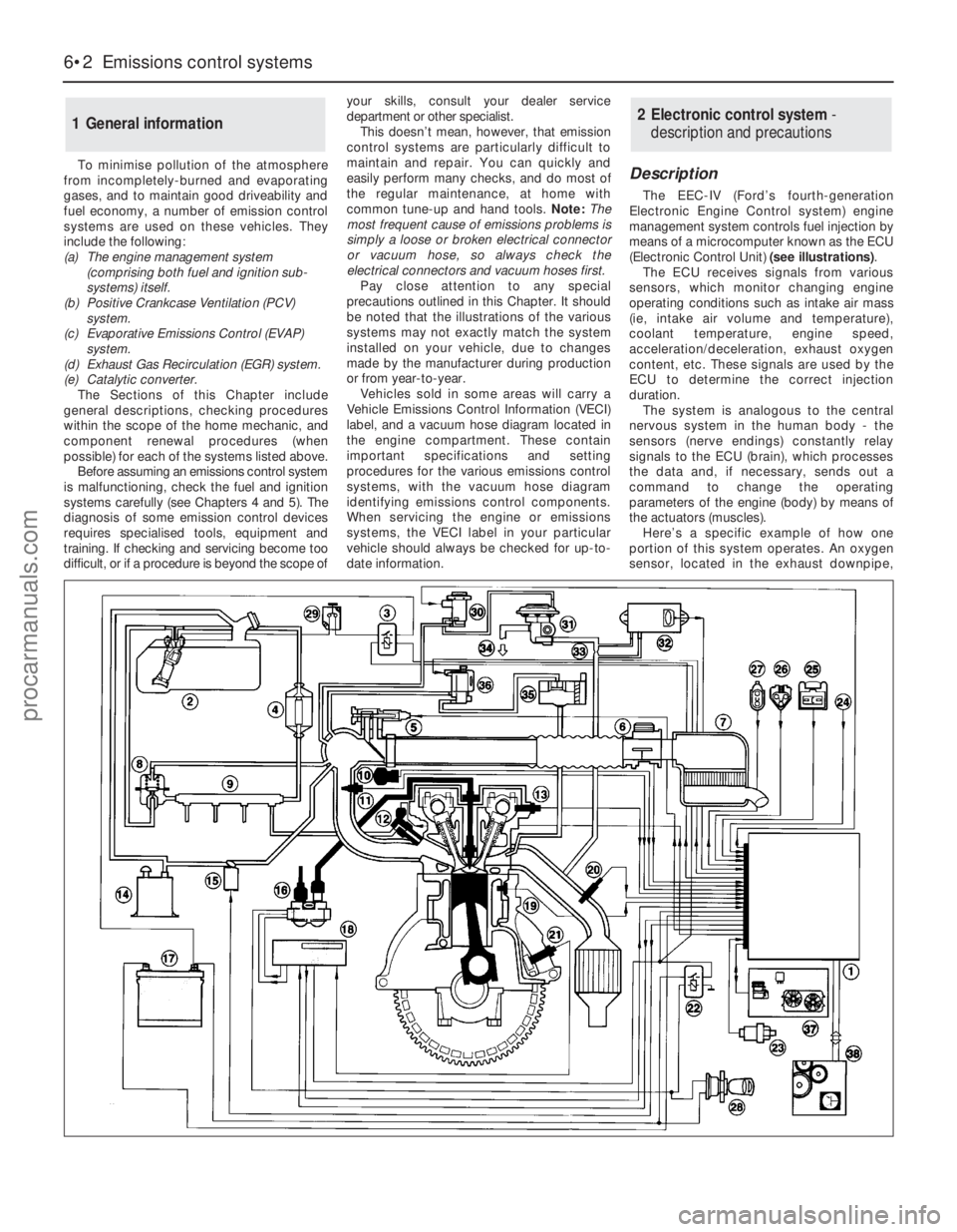
(Electronic Control Unit) (see illustrations).
The ECU receives signals from various
sensors, which monitor changing engine
operating conditions such as intake air mass
(ie, intake air volume and temperature),
coolant temperature, engine speed,
acceleration/deceleration, exhaust oxygen
content, etc. These signals are used by the
ECU to determine the correct injection
duration.
The system is analogous to the central
nervous system in the human body - the
sensors (nerve endings) constantly relay
signals to the ECU (brain), which processes
the data and, if necessary, sends out a
command to change the operating
parameters of the engine (body) by means of
the actuators (muscles).
Here’s a specific example of how one
portion of this system operates. An oxygen
sensor, located in the exhaust downpipe,
2 Electronic control system -
description and precautions1 General information
6•2 Emissions control systems
procarmanuals.com
Page 138 of 279
constantly monitors the oxygen content of the
exhaust gas. If the percentage of oxygen in
the exhaust gas is incorrect, an electrical
signal is sent to the ECU. The ECU processes
this information, and then sends a command
to the fuel injection system, telling it to change
the air/fuel mixture; the end result is an air/fuel
mixture ratio which is constantly maintained
at a predetermined ratio, regardless of driving
conditions. This happens in a fraction of a
second, and goes on almost all the time while
the engine is running - the exceptions are that
the ECU cuts out the system and runs the
engine on values pre-programmed
(“mapped”) into its memory both while the
oxygen sensor is reaching its normal
operating temperature after the engine has
been started from cold, and when the throttle
is fully open for full acceleration.
In the event of a sensor malfunction, a
back-up circuit will take over, to provide
driveability until the problem is identified and
fixed.
Precautions
(a) Always disconnect the power by
uncoupling the battery terminals - see
Section 1 of Chapter 5 - before removing
any of the electronic control system’s
electrical connectors.
(b) When installing a battery, be particularly
careful to avoid reversing the positive and
negative battery leads.
(c) Do not subject any components of the
system (especially the ECU) to severe
impact during removal or installation.
(d) Do not be careless during fault diagnosis.
Even slight terminal contact can invalidate
a testing procedure, and damage one of
the numerous transistor circuits.
(e) Never attempt to work on the ECU, to test
it (with any kind of test equipment), or to
open its cover.
(f) If you are inspecting electronic control
system components during rainy weather,
make sure that water does not enter any
part. When washing the engine
compartment, do not spray these parts or
their electrical connectors with water.
General
The various components of the fuel, ignition
and emissions control systems (not forgetting
the same ECU’s control of sub-systems such
as the radiator cooling fan, air conditioning
and automatic transmission, where
appropriate) are so closely interlinked that
diagnosis of a fault in any one component is
virtually impossible using traditional methods.
Working on simpler systems in the past, the
experienced mechanic may well have been
able to use personal skill and knowledge
immediately to pinpoint the cause of a fault, or
quickly to isolate the fault, by elimination;however, with an engine management system
integrated to this degree, this is not likely to
be possible in most instances, because of the
number of symptoms that could arise from
even a minor fault.
So that the causes of faults can be quickly
and accurately traced and rectified, the ECU
is provided with a built-in self-diagnosis
facility, which detects malfunctions in the
system’s components. When a fault occurs,
three things happen: the ECU identifies the
fault, stores a corresponding code in its
memory, and (in most cases) runs the system
using back-up values pre-programmed
(“mapped”) into its memory; some form of
driveability is thus maintained, to enable the
vehicle to be driven to a garage for attention.
Any faults that may have occurred are
indicated in the form of three-digit codes
when the system is connected (via the built-in
diagnosis or self-test connectors, as
appropriate) to special diagnostic equipment -
this points the user in the direction of the
faulty circuit, so that further tests can pinpoint
the exact location of the fault.
Given below is the procedure that would be
followed by a Ford technician to trace a fault
from scratch. Should your vehicle’s engine
management system develop a fault, read
through the procedure and decide how much
you can attempt, depending on your skill and
experience and the equipment available to
you, or whether it would be simpler to have
the vehicle attended to by your local Ford
dealer. If you are concerned about the
apparent complexity of the system, however,
remember the comments made in the fourth
paragraph of Section 1 of this Chapter; the
preliminary checks require nothing but care,
patience and a few minor items of equipment,
and may well eliminate the majority of faults.
(a) Preliminary checks
(b) Fault code read-out *
(c) Check ignition timing and base idle
speed. Recheck fault codes to establish
whether fault has been cured or not *
(d) Carry out basic check of ignition system
components. Recheck fault codes to
establish whether fault has been cured or
not *
(e) Carry out basic check of fuel system
components. Recheck fault codes to
establish whether fault has been cured or
not *
(f) If fault is still not located, carry out system
test *
Note:Operations marked with an asterisk
require special test equipment.
Preliminary checks
Note:When carrying out these checks to
trace a fault, remember that if the fault has
appeared only a short time after any part of
the vehicle has been serviced or overhauled,
the first place to check is where that work was
carried out, however unrelated it may appear,
to ensure that no carelessly-refitted
components are causing the problem.If you are tracing the cause of a “partial”
engine fault, such as lack of performance, in
addition to the checks outlined below, check
the compression pressures (see Part A of
Chapter 2) and bear in mind the possibility
that one of the hydraulic tappets might be
faulty, producing an incorrect valve clearance.
Check also that the fuel filter has been
renewed at the recommended intervals.
If the system appears completely dead,
remember the possibility that the
alarm/inhibitor system may be responsible.
1The first check for anyone without special
test equipment is to switch on the ignition,
and to listen for the fuel pump (the sound of
an electric motor running, audible from
beneath the rear seats); assuming there is
sufficient fuel in the tank, the pump should
start and run for approximately one or two
seconds, then stop, each time the ignition is
switched on. If the pump runs continuously all
the time the ignition is switched on, the
electronic control system is running in the
back-up (or “limp-home”) mode referred to by
Ford as “Limited Operation Strategy” (LOS).
This almost certainly indicates a fault in the
ECU itself, and the vehicle should therefore be
taken to a Ford dealer for a full test of the
complete system using the correct diagnostic
equipment; do not waste time trying to test
the system without such facilities.
2If the fuel pump is working correctly (or not
at all), a considerable amount of fault
diagnosis is still possible without special test
equipment. Start the checking procedure as
follows.
3Open the bonnet and check the condition
of the battery connections - remake the
connections or renew the leads if a fault is
found (Chapter 5). Use the same techniques
to ensure that all earth points in the engine
compartment provide good electrical contact
through clean, metal-to-metal joints, and that
all are securely fastened. (In addition to the
earth connection at the engine lifting eye and
that from the transmission to the
body/battery, there is one earth connection
behind each headlight assembly, and one
below the power steering fluid reservoir.)
4Referring to the information given in
Chapter 12 and in the wiring diagrams at the
back of this manual, check that all fuses
protecting the circuits related to the engine
management system are in good condition.
Fit new fuses if required; while you are there,
check that all relays are securely plugged into
their sockets.
5Next work methodically around the engine
compartment, checking all visible wiring, and
the connections between sections of the
wiring loom. What you are looking for at this
stage is wiring that is obviously damaged by
chafing against sharp edges, or against
moving suspension/transmission components
and/or the auxiliary drivebelt, by being
trapped or crushed between carelessly-
refitted components, or melted by being
forced into contact with hot engine castings,
3 Diagnosis system -
general information
6•4 Emissions control systems
procarmanuals.com
Page 140 of 279
back again, as an assistant depresses the
accelerator pedal. If the valve shows any sign
of stiffness, sticking or otherwise-inhibited
movement (and the accelerator cable is
known from the previous check to be in good
condition), spray the throttle linkage with
penetrating lubricant, allow time for it to work,
and repeat the check; if no improvement is
obtained, the complete throttle housing must
be renewed (Chapter 4).
15Unclip the air cleaner cover, and check
that the air filter element and the crankcase
ventilation system filter are not clogged or
soaked. (A clogged air filter will obstruct the
intake air flow, causing a noticeable effect on
engine performance; a clogged crankcase
ventilation system filter will inhibit crankcase
“breathing”). Renew or clean the filter(s) as
appropriate; refer to the relevant Sections of
Chapter 1 for further information, if required.
Before refitting the air cleaner cover, check
that the air intake (located under the front left-
hand wing, opening behind the direction
indicator/headlight assembly) is clear. It
should be possible to blow through the intake,
or to probe it (carefully) as far as the rear of
the direction indicator light.
16Start the engine and allow it to idle.
Note:Working in the engine compartment
while the engine is running requires great care
if the risk of personal injury is to be avoided;
among the dangers are burns from contact
with hot components, or contact with moving
components such as the radiator cooling fan
or the auxiliary drivebelt. Refer to “Safety
first!” at the front of this manual before
starting, and ensure that your hands, and long
hair or loose clothing, are kept well clear of hot
or moving components at all times.
17Working from the air intake junction at the
inner wing panel, via the air cleaner assembly
and air mass meter, to the resonator, plenum
chamber, throttle housing and inlet manifold
(and including the various vacuum hoses and
pipes connected to these), check for air leaks.
Usually, these will be revealed by sucking or
hissing noises, but minor leaks may be traced
by spraying a solution of soapy water on to
the suspect joint; if a leak exists, it will be
shown by the change in engine note and the
accompanying air bubbles (or sucking-in of
the liquid, depending on the pressure
difference at that point). If a leak is found at
any point, tighten the fastening clamp and/or
renew the faulty components, as applicable.
18Similarly, work from the cylinder head, via
the manifold (and not forgetting the related
EGR and pulse-air system components) to the
tailpipe, to check that the exhaust system is
free from leaks. The simplest way of doing
this, if the vehicle can be raised and
supported safely and with complete security
while the check is made, is to temporarily
block the tailpipe while listening for the sound
of escaping exhaust gases; any leak should
be evident. If a leak is found at any point,
tighten the fastening clamp bolts and/or nuts,
renew the gasket, and/or renew the faultysection of the system, as necessary, to seal
the leak.
19It is possible to make a further check of
the electrical connections by wiggling each
electrical connector of the system in turn as
the engine is idling; a faulty connector will be
immediately evident from the engine’s
response as contact is broken and remade. A
faulty connector should be renewed to ensure
the future reliability of the system; note that
this may mean the renewal of that entire
section of the loom - see your local Ford
dealer for details.
20Switch off the engine. If the fault is not yet
identified, the next step is to check the
ignition voltages, using an engine analyser
with an oscilloscope - without such
equipment, the only tests possible are to
remove and check each spark plug in turn, to
check the spark plug (HT) lead connections
and resistances, and to check the
connections and resistances of the ignition
coil. Refer to the relevant Sections of
Chapters 1 and 5.
21The final step in these preliminary checks
would be to use an exhaust gas analyser to
measure the CO level at the exhaust tailpipe.This check cannot be made without special
test equipment - see your local Ford dealer for
details.
Fault code read-out
22As noted in the general comments at the
beginning of this Section, the preliminary
checks outlined above should eliminate the
majority of faults from the engine
management system. If the fault is not yet
identified, the next step is to connect a fault
code reader to the ECU, so that its self-
diagnosis facility can be used to identify the
faulty part of the system; further tests can
then be made to identify the exact cause of
the fault.
23In their basic form, fault code readers are
simply hand-held electronic devices, which
take data stored within an ECU’s memory and
display it when required as two- or three-digit
fault codes. The more sophisticated versions
now available can also control sensors and
actuators, to provide more effective testing;
some can store information, so that a road
test can be carried out, and any faults
encountered during the test can be displayed
afterwards.
6•6 Emissions control systems
3.26 Location and terminal identification of engine management system self-test,
diagnosis and service connectors
1 Power steering fluid reservoir
2 Diagnosis connector - for Ford diagnostic equipment FDS 2000
3 Self-test connector - for fault code read-out - pin 17 is output terminal, pin 48 is input
terminal, pin 40/60 is earth
4 Service connector - for octane adjustment
5 Plug-in bridge - to suit 95 RON fuel
procarmanuals.com
Page 144 of 279
Ignition timing and base idle
speed check
Note:The following procedure is a check only,
essentially of the ECU. Both the ignition timing
and the base idle speed are controlled by the
ECU. The ignition timing is not adjustable at
all; the base idle speed is set in production,
and should not be altered.
38If the fault code read-out (with any checks
resulting from it) has not eliminated the fault,
the next step is to check the ECU’s control of
the ignition timing and the base idle speed.
This task requires the use of a Ford STAR
tester (a proprietary fault code reader can be
used only if it is capable of inducing the ECU
to enter its “Service Adjustment Programme”),
coupled with an accurate tachometer and a
good-quality timing light. Without this
equipment, the task is not possible; the
vehicle must be taken to a Ford dealer for
attention.
39To make the check, apply the handbrake,
switch off the air conditioning (where fitted)
and any other electrical loads (lights, heated
rear window, etc), then select neutral (manual
transmission) or the “P” position (automatic
transmission). Start the engine, and warm it
up to normal operating temperature. The
radiator electric cooling fan must be running
continuously while the check is made; this
should be activated by the ECU, when
prompted by the tester. Switch off the engine,
and connect the test equipment as directed
by the manufacturer - refer to paragraph 26
above for details of STAR tester connection.
40Raise and support the front of the vehicle
securely, and remove the auxiliary drivebelt
cover (see Chapter 1). Emphasise the two
pairs of notches in the inner and outer rims of
the crankshaft pulley, using white paint. Note
that an ignition timing reference mark is not
provided on the pulley - in the normal
direction of crankshaft rotation (clockwise,
seen from the right-hand side of the vehicle)
the first pair of notches are irrelevant to the
vehicles covered in this manual, while the
second pair indicate Top Dead Centre (TDC)
when aligned with the rear edge of the raised
mark on the sump; when checking the ignition
timing, therefore, the (rear edge of the) sumpmark should appear just before the TDC
notches (see Part A of Chapter 2, Section 4,
for further information if required).
41Start the engine and allow it to idle. Work
through the engine-running test procedure
until the ECU enters its “Service Adjustment
Programme” - see paragraph 35 above.
42Use the timing light to check that the
timing marks appear approximately as
outlined above at idle speed. Do not spend
too much time on this check; if the timing
appears to be incorrect, the system may have
a fault, and a full system test must be carried
out (see below) to establish its cause.
43Using the tachometer, check that the
base idle speed is as given in the
Specifications Section of Chapter 4.
44If the recorded speed differs significantly
from the specified value, check for air leaks,
as described in the preliminary checks
(paragraphs 15 to 18 above), or any other
faults which might cause the discrepancy.
45The base idle speed is set in production
by means of an air bypass screw (located in
the front right-hand corner of the throttle
housing) which controls the amount of air that
is allowed to pass through a bypass passage,
past the throttle valve when it is fully closed in
the idle position; the screw is then sealed with
a white tamperproof plug (see illustration). In
service, the idle speed is controlled by the
ECU, which has the ability to compensate for
engine wear, build-up of dirt in the throttle
housing, and other factors which might
require changes in idle speed. The air bypass
screw setting should not, therefore, be
altered. If any alterations are made, a blue
tamperproof plug must be fitted, and the
engine should be allowed to idle for at least
five minutes on completion, so that the ECU
can re-learn its idle values.
46When both checks have been made and
the “Service Adjustment Programme” is
completed, follow the tester instructions to
return to the fault code read-out, and
establish whether the fault has been cured or
not.
Basic check of ignition system
47If the checks so far have not eliminated
the fault, the next step is to carry out a basic
check of the ignition system components,
using an engine analyser with an oscilloscope
- without such equipment, the only tests
possible are to remove and check each spark
plug in turn, to check the spark plug (HT) lead
connections and resistances, and to check
the connections and resistances of the
ignition coil. Refer to the relevant Sections of
Chapters 1 and 5.
Basic check of fuel system
48If the checks so far have not eliminated
the fault, the next step is to carry out a basic
check of the fuel system components.
49Assuming that the preliminary checks
have established that the fuel pump is
operating correctly, that the fuel filter isunlikely to be blocked, and also that there are
no leaks in the system, the next step is to
check the fuel pressure (see Chapter 4). If this
is correct, check the injectors (see Chapter 4)
and the Positive Crankcase Ventilation system
(see Chapter 1).
System test
50The final element of the Ford testing
procedure is to carry out a system test, using
a break-out box - this is a device that is
connected between the ECU and its electrical
connector, so that the individual circuits
indicated by the fault code read-out can be
tested while connected to the system, if
necessary with the engine running. In the case
of many of the system’s components, this
enables their output voltages to be measured
- a more accurate means of testing.
51In addition to the break-out box and the
adaptors required to connect it, several items
of specialist equipment are needed to
complete these tests. This puts them quite
beyond the scope of many smaller dealers, let
alone the DIY owner; the vehicle should be
taken to a Ford dealer for attention.
Note:This Section is concerned principally
with the sensors which give the ECU the
information it needs to control the various
engine management sub-systems - for further
details of those systems and their other
components, refer to the relevant Chapter of
this manual.
General
ECU (Electronic Control Unit)
1This component is the heart of the entire
engine management system, controlling the
fuel injection, ignition and emissions control
systems. It also controls sub-systems such as
the radiator cooling fan, air conditioning and
automatic transmission, where appropriate.
Refer to Section 2 of this Chapter for an
illustration of how it works.
Air mass meter
2This uses a “hot-wire” system, sending the
ECU a constantly-varying (analogue) voltage
signal corresponding to the mass of air
passing into the engine. Since air mass varies
with temperature (cold air being denser than
warm), measuring air mass provides the ECU
with a very accurate means of determining the
correct amount of fuel required to achieve the
ideal air/fuel mixture ratio.
Crankshaft speed/position sensor
3This is an inductive pulse generator bolted
(in a separate bracket) to the cylinder
block/crankcase, to scan the ridges between
36 holes machined in the inboard (right-hand)
face of the flywheel/driveplate. As each ridge
4 Information sensors -
general information, testing,
removal and refitting
6•10 Emissions control systems
3.45 Throttle housing air bypass screw is
sealed on production with a white
tamperproof plug (arrowed)
procarmanuals.com
Page 145 of 279
passes the sensor tip, a signal is generated,
which is used by the ECU to determine engine
speed.
4The ridge between the 35th and 36th holes
(corresponding to 90° BTDC) is missing - this
step in the incoming signals is used by the
ECU to determine crankshaft (ie, piston)
position.
Camshaft position sensor
5This is bolted to the rear left-hand end of
the cylinder head, to register with a lobe on
the inlet camshaft. It functions in the same
way as the crankshaft speed/position sensor,
producing a series of pulses (corresponding
to No 1 cylinder at 46° ATDC); this gives the
ECU a reference point, to enable it to
determine the firing order, and operate the
injectors in the appropriate sequence.
Coolant temperature sensor
6This component, which is screwed into the
top of the thermostat housing, is an NTC
(Negative Temperature Coefficient) thermistor
- that is, a semi-conductor whose electrical
resistance decreases as its temperature
increases. It provides the ECU with a
constantly-varying (analogue) voltage signal,
corresponding to the temperature of the
engine coolant. This is used to refine the
calculations made by the ECU, when
determining the correct amount of fuel
required to achieve the ideal air/fuel mixture
ratio.
Intake air temperature sensor
7This component, which is screwed into the
underside of the air intake resonator, is also an
NTC thermistor - see the previous paragraph -
providing the ECU with a signal corresponding
to the temperature of air passing into the
engine. This is used to refine the calculations
made by the ECU, when determining the
correct amount of fuel required to achieve the
ideal air/fuel mixture ratio.
Throttle potentiometer
8This is mounted on the end of the throttle
valve spindle, to provide the ECU with a
constantly-varying (analogue) voltage signal
corresponding to the throttle opening. This
allows the ECU to register the driver’s input
when determining the amount of fuel required
by the engine.
Vehicle speed sensor
9This component is a Hall-effect generator,
mounted on the transmission’s speedometer
drive. It supplies the ECU with a series of
pulses corresponding to the vehicle’s road
speed, enabling the ECU to control features
such as the fuel shut-off on the overrun, and
to provide information for the trip computer,
adaptive damping and cruise control systems
(where fitted).
Power steering pressure switch
10This is a pressure-operated switch,
screwed into the power steering system’shigh-pressure pipe. Its contacts are normally
closed, opening when the system reaches the
specified pressure - on receiving this signal,
the ECU increases the idle speed, to
compensate for the additional load on the
engine.
Exhaust gas pressure differential
sensor
11This component measures the difference
in pressure of the exhaust gases across a
venturi (restriction) in the Exhaust Gas
Recirculation (EGR) system’s pipe, and sends
the ECU a voltage signal corresponding to the
pressure difference.
Oxygen sensor
12The oxygen sensor in the exhaust system
provides the ECU with constant feedback -
“closed-loop” control - which enables it to
adjust the mixture to provide the best possible
conditions for the catalytic converter to
operate.
13The sensor has a built-in heating element
which is controlled by the ECU, in order to
bring the sensor’s tip to an efficient operating
temperature as rapidly as possible. The
sensor’s tip is sensitive to oxygen, and sends
the ECU a varying voltage depending on the
amount of oxygen in the exhaust gases. If the
intake air/fuel mixture is too rich, the exhaust
gases are low in oxygen, so the sensor sends
a low-voltage signal, the voltage rising as the
mixture weakens and the amount of oxygen in
the exhaust gases rises. Peak conversion
efficiency of all major pollutants occurs if the
intake air/fuel mixture is maintained at the
chemically-correct ratio for the complete
combustion of petrol, of 14.7 parts (by weight)
of air to 1 part of fuel (the “stoichiometric”
ratio). The sensor output voltage alters sharply
around this point, the ECU using the signal
change as a reference point, and correcting
the air/fuel mixture by altering the fuel injector
pulse width.
Air conditioning system
14Two pressure-operated switches and the
compressor clutch solenoid are connected to
the ECU, to enable it to determine how the
system is operating. The ECU can increase
idle speed or switch off the system, as
necessary, so that normal vehicle operation
and driveability are not impaired. See Chapter
3 for further details, but note that diagnosis
and repair should be left to a dealer service
department or air conditioning specialist.
Automatic transmission
15In addition to the driver’s controls, the
transmission has a speed sensor, a fluid
temperature sensor (built into the solenoid
valve unit), and a selector lever position
sensor. All of these are connected to the ECU,
to enable it to control the transmission
through the solenoid valve unit. See Part B of
Chapter 7 for further details.
Testing
ECU (Electronic Control Unit)
16 Do notattempt to “test” the ECU with any
kind of equipment. If it is thought to be faulty,
take the vehicle to a Ford dealer for the entire
electronic control system to be checked using
the proper diagnostic equipment. Only if all
other possibilities have been eliminated should
the ECU be considered at fault, and replaced.
Air mass meter
17Testing of this component is beyond the
scope of the DIY mechanic, and should be left
to a Ford dealer.
Crankshaft speed/position sensor
18Unplug the electrical connector from the
sensor.
19Using an ohmmeter, measure the
resistance between the sensor terminals.
Compare this reading to the one listed in the
Specifications Section at the beginning of this
Chapter. If the indicated resistance is not
within the specified range, renew the sensor.
20Plug in the sensor’s electrical connector
on completion.
Camshaft position sensor
21The procedure is as described in
paragraphs 18 to 20 above.
Coolant temperature sensor
22Refer to Chapter 3.
Intake air temperature sensor
23Unplug the electrical connector from the
sensor.
24Using an ohmmeter, measure the
resistance between the sensor terminals.
Depending on the temperature of the sensor
tip, the resistance measured will vary, but it
should be within the broad limits given in the
Specifications Section of this Chapter. If the
sensor’s temperature is varied - by placing it
in a freezer for a while, or by warming it gently
- its resistance should alter accordingly.
25If the results obtained show the sensor to
be faulty, renew it.
Throttle potentiometer
26Remove the plenum chamber (see
Chapter 4) and unplug the potentiometer’s
electrical connector.
27Using an ohmmeter, measure the
resistance between the unit’s terminals - first
between the centre terminal and one of the
outer two, then from the centre to the
remaining outer terminal. The resistance
should be within the limits given in the
Specifications Section of this Chapter, and
should alter smoothlyas the throttle valve is
moved from the fully-closed (idle speed)
position to fully open and back again.
28If the resistance measured is significantly
different from the specified value, if there are
any breaks in continuity, or if the reading
fluctuates erratically as the throttle is
operated, the potentiometer is faulty, and
must be renewed.
Emissions control systems 6•11
6
procarmanuals.com
Page 154 of 279
hence the heat shields on the vehicle
underbody - and the casing will become
hot enough to ignite combustible
materials which brush against it. DO NOT,
therefore, park the vehicle in dry
undergrowth, over long grass or piles of
dead leaves.
(k) Remember that the catalytic converter is
FRAGILE. Do not strike it with tools
during servicing work, and take great care
when working on the exhaust system (see
Chapter 4). Ensure that the converter is
well clear of any jacks or other lifting gear
used to raise the vehicle. Do not drive the
vehicle over rough ground, road humps,
etc, in such a way as to “ground” the
exhaust system.
(l) In some cases, particularly when the
vehicle is new and/or is used for
stop/start driving, a sulphurous smell (like
that of rotten eggs) may be noticed fromthe exhaust. This is common to many
catalytic converter-equipped vehicles,
and seems to be due to the small amount
of sulphur found in some petrols reacting
with hydrogen in the exhaust, to produce
hydrogen sulphide (H
2S) gas; while this
gas is toxic, it is not produced in sufficient
amounts to be a problem. Once the
vehicle has covered a few thousand miles,
the problem should disappear - in the
meanwhile, a change of driving style, or of
the brand of petrol used, may effect a
solution.
(m) The catalytic converter on a well-
maintained and well-driven vehicle should
last for between 50 000 and 100 000
miles. From this point on, careful checks
should be made at regular intervals to
ensure that the converter is still operating
efficiently. If the converter is no longer
effective, it must be renewed.
Checking
7Checking the operation of a catalytic
converter requires expensive and
sophisticated diagnostic equipment, starting
with a high-quality exhaust gas analyser. If the
level of CO in the exhaust gases is too high, a
full check of the engine management system
must be carried out (see Section 3 of this
Chapter) to eliminate all other possibilities
before the converter is suspected of being
faulty.
8The vehicle should be taken to a Ford
dealer for this work to be carried out using the
correct diagnostic equipment; do not waste
time trying to test the system without such
facilities.
Component renewal
9The catalytic converter is part of the
exhaust system front downpipe - see Chap-
ter 4 for details of removal and refitting.
6•20 Emissions control systems
procarmanuals.com
Page 174 of 279
15Locate the steering column shaft on the
flexible coupling, swivel the clamp plate
round, then insert the bolt and tighten to the
specified torque.
16Refit the driver’s side lower trim panel.
17Refit the steering column upper and lower
shrouds.
18Reconnect the battery negative lead.
Removal
1Disconnect the battery negative (earth) lead
(refer to Chapter 5, Section 1).
2Turn the steering wheel so that the front
wheels are in the straight-ahead position.
Remove the ignition key, then turn the
steering wheel slightly as necessary until the
steering lock engages.
3Unscrew the clamp plate bolt securing the
steering column shaft to the flexible coupling.
Swivel the clamp plate around, and disengage
it from the flexible coupling stub.
4Carefully prise the rubber boot from the
bulkhead, and withdraw it into the passenger
compartment. Take care not to damage the
sealing lip of the boot.
5Using an Allen key, unscrew the clamp bolt
securing the flexible coupling to the pinion
shaft on the steering gear, and withdraw the
coupling from inside the vehicle.
Refitting
6Refitting is a reversal of the removal
procedure, but tighten the clamp bolts to the
specified torque. Make sure that the rubber
boot engages correctly in the bulkhead and
on the flexible coupling.
Removal
1Remove the steering column flexible
coupling as described in Section 29.
2Apply the handbrake, then jack up the frontof the vehicle and support it on axle stands.
Remove both front wheels.
3Working beneath the vehicle, unbolt the
rear engine mounting from the transmission
and underbody.
4Extract the split pins from the track rod end
balljoint nuts, then unscrew the nuts, and
detach the rods from the arms on the steering
knuckles using a conventional balljoint
removal tool. Take care not to damage the
balljoint seals.
5Position a suitable container beneath the
steering gear, then unscrew the union nuts
securing the power steering fluid supply,
return, and cooler lines to the steering gear.
Identify the lines for position, then unbolt the
clamps, disconnect the lines, and allow the
fluid to drain into the container. Cover the
apertures in the steering gear and also the
ends of the fluid pipes, to prevent the ingress
of dust and dirt into the hydraulic circuit.
6Unscrew and remove the steering gear
mounting bolts. The bolts are located on top
of the steering gear, and are difficult to reach.
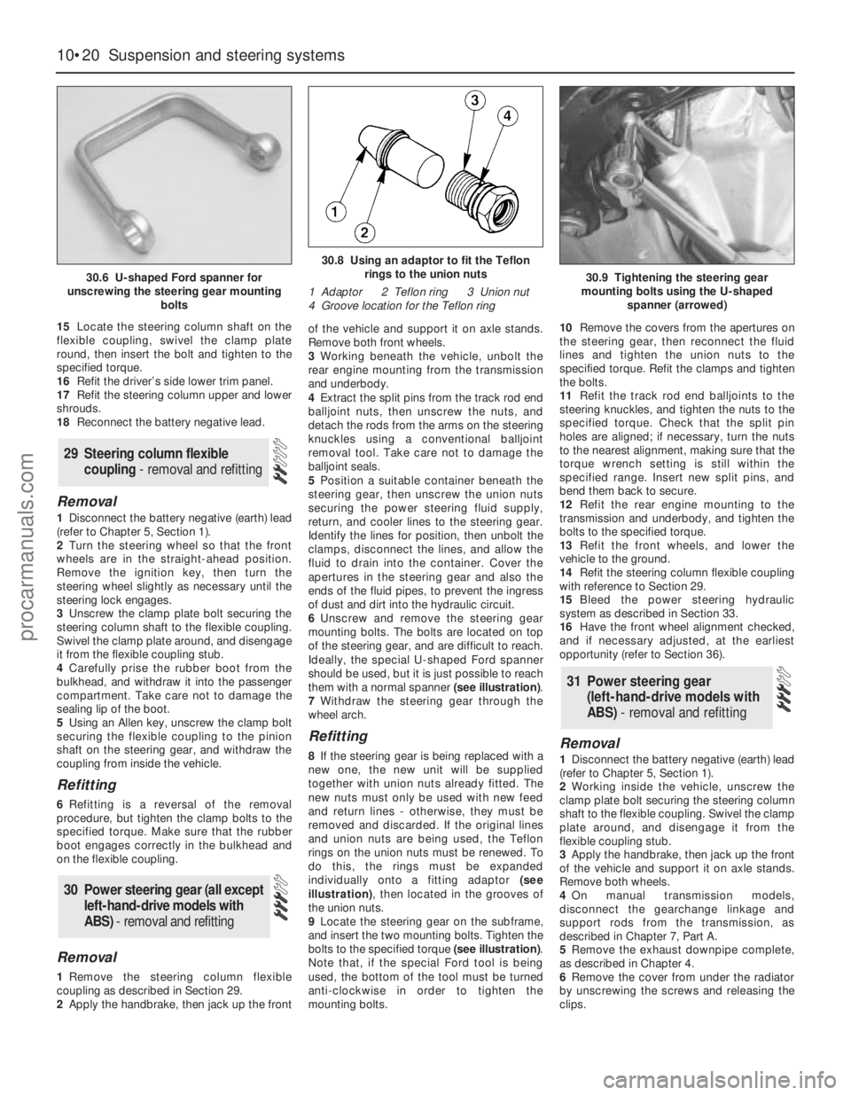
Ideally, the special U-shaped Ford spanner
should be used, but it is just possible to reach
them with a normal spanner (see illustration).
7Withdraw the steering gear through the
wheel arch.
Refitting
8If the steering gear is being replaced with a
new one, the new unit will be supplied
together with union nuts already fitted. The
new nuts must only be used with new feed
and return lines - otherwise, they must be
removed and discarded. If the original lines
and union nuts are being used, the Teflon
rings on the union nuts must be renewed. To
do this, the rings must be expanded
individually onto a fitting adaptor (see
illustration), then located in the grooves of
the union nuts.
9Locate the steering gear on the subframe,
and insert the two mounting bolts. Tighten the
bolts to the specified torque (see illustration).
Note that, if the special Ford tool is being
used, the bottom of the tool must be turned
anti-clockwise in order to tighten the
mounting bolts.10Remove the covers from the apertures on
the steering gear, then reconnect the fluid
lines and tighten the union nuts to the
specified torque. Refit the clamps and tighten
the bolts.
11Refit the track rod end balljoints to the
steering knuckles, and tighten the nuts to the
specified torque. Check that the split pin
holes are aligned; if necessary, turn the nuts
to the nearest alignment, making sure that the
torque wrench setting is still within the
specified range. Insert new split pins, and
bend them back to secure.
12Refit the rear engine mounting to the
transmission and underbody, and tighten the
bolts to the specified torque.
13Refit the front wheels, and lower the
vehicle to the ground.
14Refit the steering column flexible coupling
with reference to Section 29.
15Bleed the power steering hydraulic
system as described in Section 33.
16Have the front wheel alignment checked,
and if necessary adjusted, at the earliest
opportunity (refer to Section 36).Removal
1Disconnect the battery negative (earth) lead
(refer to Chapter 5, Section 1).
2Working inside the vehicle, unscrew the
clamp plate bolt securing the steering column
shaft to the flexible coupling. Swivel the clamp
plate around, and disengage it from the
flexible coupling stub.
3Apply the handbrake, then jack up the front
of the vehicle and support it on axle stands.
Remove both wheels.
4On manual transmission models,
disconnect the gearchange linkage and
support rods from the transmission, as
described in Chapter 7, Part A.
5Remove the exhaust downpipe complete,
as described in Chapter 4.
6Remove the cover from under the radiator
by unscrewing the screws and releasing the
clips.
31 Power steering gear
(left-hand-drive models with
ABS) - removal and refitting
30 Power steering gear (all except
left-hand-drive models with
ABS) - removal and refitting
29 Steering column flexible
coupling - removal and refitting
10•20 Suspension and steering systems
30.6 U-shaped Ford spanner for
unscrewing the steering gear mounting
bolts
30.8 Using an adaptor to fit the Teflon
rings to the union nuts
1 Adaptor 2 Teflon ring 3 Union nut
4 Groove location for the Teflon ring
30.9 Tightening the steering gear
mounting bolts using the U-shaped
spanner (arrowed)
procarmanuals.com