1993 FORD MONDEO bonnet
[x] Cancel search: bonnetPage 210 of 279
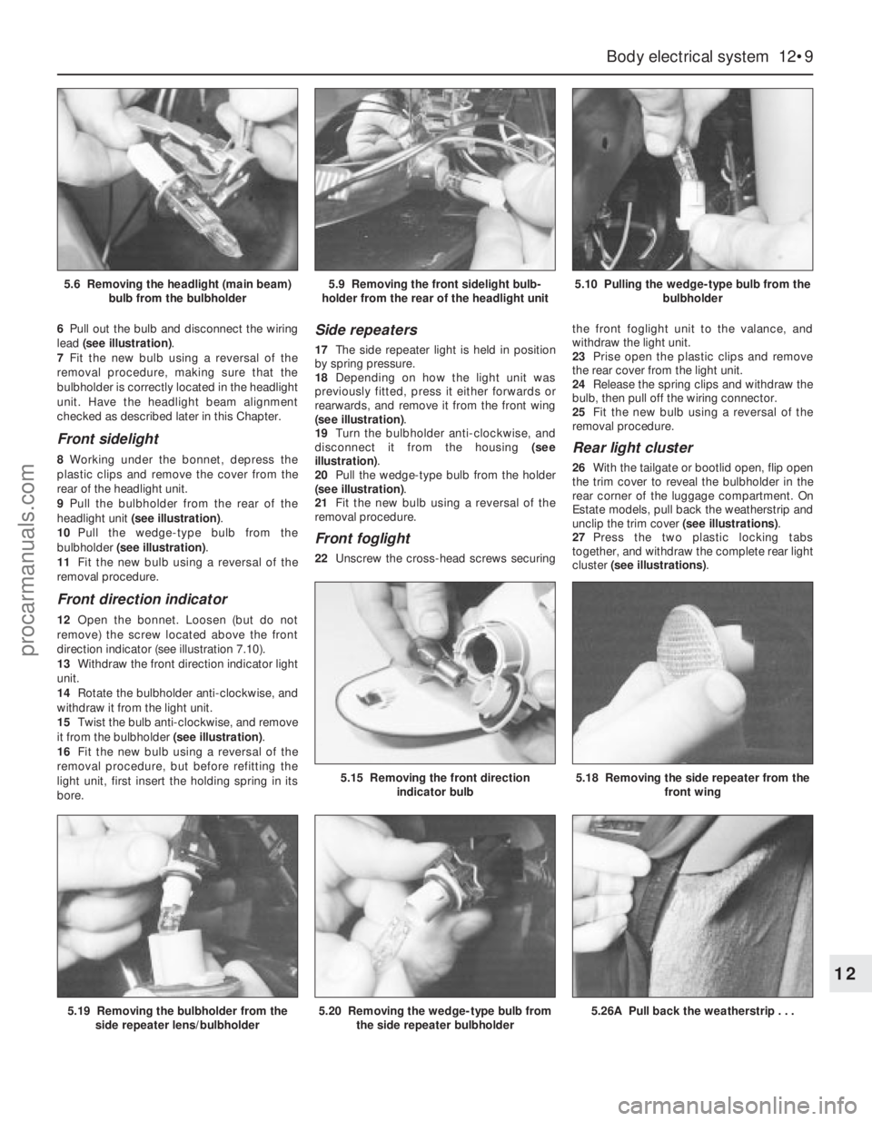
6Pull out the bulb and disconnect the wiring
lead (see illustration).
7Fit the new bulb using a reversal of the
removal procedure, making sure that the
bulbholder is correctly located in the headlight
unit. Have the headlight beam alignment
checked as described later in this Chapter.
Front sidelight
8Working under the bonnet, depress the
plastic clips and remove the cover from the
rear of the headlight unit.
9Pull the bulbholder from the rear of the
headlight unit (see illustration).
10Pull the wedge-type bulb from the
bulbholder (see illustration).
11Fit the new bulb using a reversal of the
removal procedure.
Front direction indicator
12Open the bonnet. Loosen (but do not
remove) the screw located above the front
direction indicator (see illustration 7.10).
13Withdraw the front direction indicator light
unit.
14Rotate the bulbholder anti-clockwise, and
withdraw it from the light unit.
15Twist the bulb anti-clockwise, and remove
it from the bulbholder (see illustration).
16Fit the new bulb using a reversal of the
removal procedure, but before refitting the
light unit, first insert the holding spring in its
bore.
Side repeaters
17The side repeater light is held in position
by spring pressure.
18Depending on how the light unit was
previously fitted, press it either forwards or
rearwards, and remove it from the front wing
(see illustration).
19Turn the bulbholder anti-clockwise, and
disconnect it from the housing (see
illustration).
20Pull the wedge-type bulb from the holder
(see illustration).
21Fit the new bulb using a reversal of the
removal procedure.
Front foglight
22Unscrew the cross-head screws securingthe front foglight unit to the valance, and
withdraw the light unit.
23Prise open the plastic clips and remove
the rear cover from the light unit.
24Release the spring clips and withdraw the
bulb, then pull off the wiring connector.
25Fit the new bulb using a reversal of the
removal procedure.
Rear light cluster
26With the tailgate or bootlid open, flip open
the trim cover to reveal the bulbholder in the
rear corner of the luggage compartment. On
Estate models, pull back the weatherstrip and
unclip the trim cover (see illustrations).
27Press the two plastic locking tabs
together, and withdraw the complete rear light
cluster (see illustrations).
Body electrical system 12•9
12
5.19 Removing the bulbholder from the
side repeater lens/bulbholder5.20 Removing the wedge-type bulb from
the side repeater bulbholder5.26A Pull back the weatherstrip . . .
5.15 Removing the front direction
indicator bulb5.18 Removing the side repeater from the
front wing
5.6 Removing the headlight (main beam)
bulb from the bulbholder5.9 Removing the front sidelight bulb-
holder from the rear of the headlight unit5.10 Pulling the wedge-type bulb from the
bulbholder
procarmanuals.com
Page 212 of 279
Engine compartment light
1With the bonnet open, pull the wedge-type
bulb from the bulbholder.
2Fit the new bulb using a reversal of the
removal procedure.
Interior lights
3Switch off the interior light by locating the
switch in its middle position.
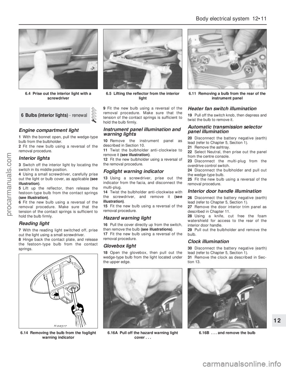
4Using a small screwdriver, carefully prise
out the light or bulb cover, as applicable (see
illustration).
5Lift up the reflector, then release the
festoon-type bulb from the contact springs
(see illustration).
6Fit the new bulb using a reversal of the
removal procedure. Make sure that the
tension of the contact springs is sufficient to
hold the bulb firmly.
Reading light
7With the reading light switched off, prise
out the light using a small screwdriver.
8Hinge back the contact plate, and release
the festoon-type bulb from the contact
springs.9Fit the new bulb using a reversal of the
removal procedure. Make sure that the
tension of the contact springs is sufficient to
hold the bulb firmly.
Instrument panel illumination and
warning lights
10Remove the instrument panel as
described in Section 10.
11Twist the bulbholder anti-clockwise to
remove it (see illustration).
12Fit the new bulbholder using a reversal of
the removal procedure.
Foglight warning indicator
13Using a screwdriver, prise out the
indicator from the facia, and disconnect the
multi-plug.
14Twist the bulbholder anti-clockwise with
the screwdriver, and remove it (see
illustration).
15Fit the new bulb using a reversal of the
removal procedure.
Hazard warning light
16Pull the cover directly up from the switch,
then remove the bulb (see illustrations).
17Fit the new bulb using a reversal of the
removal procedure.
Glovebox light
18Open the glovebox, then pull out the
wedge-type bulb from the light located under
the upper edge.
Heater fan switch illumination
19Pull off the switch knob, then depress and
twist the bulb to remove it.
Automatic transmission selector
panel illumination
20Disconnect the battery negative (earth)
lead (refer to Chapter 5, Section 1).
21Remove the ashtray.
22Select Neutral, then prise out the panel
from the centre console.
23Disconnect the multi-plug from the
overdrive control switch.
24Disconnect the bulbholder and pull out
the wedge-type bulb.
25Fit the new bulb using a reversal of the
removal procedure.
Interior door handle illumination
26Disconnect the battery negative (earth)
lead (refer to Chapter 5, Section 1).
27Remove the door interior trim panel as
described in Chapter 11.
28Using a knife, cut free the foam
watershield for access to the rear of the
interior door handle.
29Pull out the bulbholder and remove the
bulb.
Clock illumination
30Disconnect the battery negative (earth)
lead (refer to Chapter 5, Section 1).
31Remove the clock as described in Sec-
tion 13.
6 Bulbs (interior lights) - renewal
Body electrical system 12•11
12
6.14 Removing the bulb from the foglight
warning indicator6.16A Pull off the hazard warning light
cover . . .6.16B . . . and remove the bulb
6.4 Prise out the interior light with a
screwdriver6.5 Lifting the reflector from the interior
light6.11 Removing a bulb from the rear of the
instrument panel
procarmanuals.com
Page 213 of 279
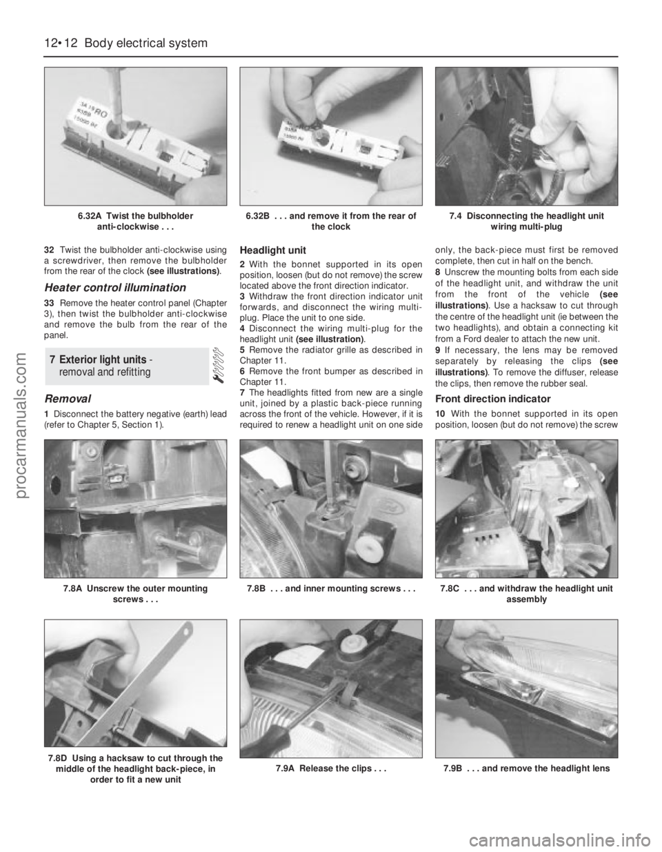
32Twist the bulbholder anti-clockwise using
a screwdriver, then remove the bulbholder
from the rear of the clock (see illustrations).
Heater control illumination
33Remove the heater control panel (Chapter
3), then twist the bulbholder anti-clockwise
and remove the bulb from the rear of the
panel.
Removal
1Disconnect the battery negative (earth) lead
(refer to Chapter 5, Section 1).
Headlight unit
2With the bonnet supported in its open
position, loosen (but do not remove) the screw
located above the front direction indicator.
3Withdraw the front direction indicator unit
forwards, and disconnect the wiring multi-
plug. Place the unit to one side.
4Disconnect the wiring multi-plug for the
headlight unit (see illustration).
5Remove the radiator grille as described in
Chapter 11.
6Remove the front bumper as described in
Chapter 11.
7The headlights fitted from new are a single
unit, joined by a plastic back-piece running
across the front of the vehicle. However, if it is
required to renew a headlight unit on one sideonly, the back-piece must first be removed
complete, then cut in half on the bench.
8Unscrew the mounting bolts from each side
of the headlight unit, and withdraw the unit
from the front of the vehicle (see
illustrations). Use a hacksaw to cut through
the centre of the headlight unit (ie between the
two headlights), and obtain a connecting kit
from a Ford dealer to attach the new unit.
9If necessary, the lens may be removed
separately by releasing the clips (see
illustrations). To remove the diffuser, release
the clips, then remove the rubber seal.
Front direction indicator
10With the bonnet supported in its open
position, loosen (but do not remove) the screw
7 Exterior light units -
removal and refitting
12•12 Body electrical system
6.32A Twist the bulbholder
anti-clockwise . . .6.32B . . . and remove it from the rear of
the clock7.4 Disconnecting the headlight unit
wiring multi-plug
7.8D Using a hacksaw to cut through the
middle of the headlight back-piece, in
order to fit a new unit7.9A Release the clips . . .7.9B . . . and remove the headlight lens
7.8A Unscrew the outer mounting
screws . . .7.8B . . . and inner mounting screws . . .7.8C . . . and withdraw the headlight unit
assembly
procarmanuals.com
Page 216 of 279
6Similarly remove the fuel gauge and
temperature gauge by unscrewing the single
screws.
7Remove all the pin contacts.
8Using a small punch, push in the multi-plug
securing pins, and remove the multi-plugs.
9Carefully lift the printed circuit from the
location dowels on the housing, taking care
not to damage it.
Refitting
10Refitting is a reversal of the removal
procedure.
Removal
1Remove the windscreen wiper arms as
described in Section 15.
2With the bonnet closed, release the grille
panel upper edge from just in front of the
windscreen, by prising off the caps and
unscrewing the upper retaining screws.
3Open the bonnet, and support with the
stay.
4Pull off the sealing strip from the cross
panel at the rear of the engine compartment.
5Unscrew the lower screws, and remove the
grille panel halves from in front of thewindscreen, withdrawing first one side and
then the other.
6Disconnect the battery negative (earth) lead
(refer to Chapter 5, Section 1).
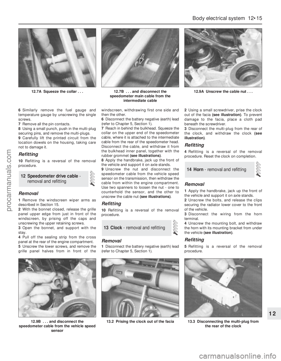
7Reach in behind the bulkhead. Squeeze the
collar on the upper end of the speedometer
cable, where it is attached to the intermediate
cable from the rear of the speedometer head.
Disconnect the cable, and withdraw it from
the bulkhead inner panel, together with the
rubber grommet (see illustrations).
8Apply the handbrake, jack up the front of
the vehicle and support it on axle stands.
9Unscrew the nut and disconnect the
speedometer cable from the vehicle speed
sensor on the transmission, then withdraw the
cable from within the engine compartment.
Use two spanners to loosen the nut - one to
counterhold the sensor, and the other to
unscrew the cable nut (see illustrations).Refitting
10Refitting is a reversal of the removal
procedure.
Removal
1Disconnect the battery negative (earth) lead
(refer to Chapter 5, Section 1).2Using a small screwdriver, prise the clock
out of the facia (see illustration). To prevent
damage to the facia, place a cloth pad
beneath the screwdriver.
3Disconnect the multi-plug from the rear of
the clock, and withdraw the clock (see
illustration).
Refitting
4Refitting is a reversal of the removal
procedure. Reset the clock on completion.
Removal
1Apply the handbrake, jack up the front of
the vehicle and support it on axle stands.
2Unscrew the bolts, and release the clips
securing the radiator lower cover to the front
of the vehicle.
3Disconnect the wiring from the horn
terminal.
4Unscrew the mounting bolt, and withdraw
the horn with its mounting bracket from under
the vehicle (see illustration).
Refitting
5Refitting is a reversal of the removal
procedure.
14 Horn - removal and refitting
13 Clock- removal and refitting
12 Speedometer drive cable -
removal and refitting
Body electrical system 12•15
12
12.9B . . . and disconnect the
speedometer cable from the vehicle speed
sensor13.2 Prising the clock out of the facia13.3 Disconnecting the multi-plug from
the rear of the clock
12.7A Squeeze the collar . . .12.7B . . . and disconnect the
speedometer main cable from the
intermediate cable12.9A Unscrew the cable nut . . .
procarmanuals.com
Page 217 of 279
Removal
1Disconnect the battery negative (earth) lead
(refer to Chapter 5, Section 1). If the windscreen
wiper arms are to be removed, close the bonnet.
2With the wiper(s) “parked” (ie in the normal
at-rest position), mark the positions of the
blade(s) on the screen, using a wax crayon or
strips of masking tape.
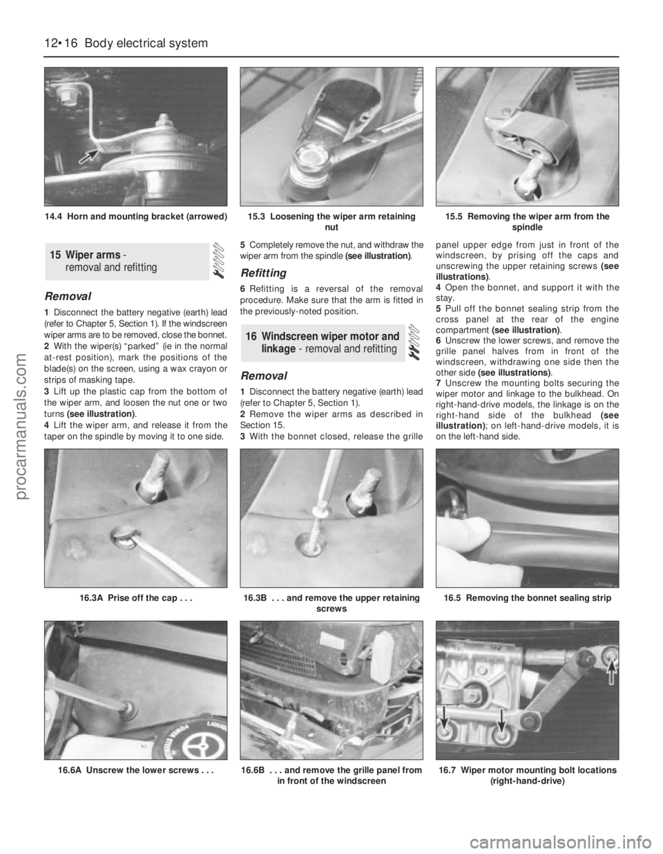
3Lift up the plastic cap from the bottom of
the wiper arm, and loosen the nut one or two
turns (see illustration).
4Lift the wiper arm, and release it from the
taper on the spindle by moving it to one side.5Completely remove the nut, and withdraw the
wiper arm from the spindle (see illustration).
Refitting
6Refitting is a reversal of the removal
procedure. Make sure that the arm is fitted in
the previously-noted position.
Removal
1Disconnect the battery negative (earth) lead
(refer to Chapter 5, Section 1).
2Remove the wiper arms as described in
Section 15.
3With the bonnet closed, release the grillepanel upper edge from just in front of the
windscreen, by prising off the caps and
unscrewing the upper retaining screws (see
illustrations).
4Open the bonnet, and support it with the
stay.
5Pull off the bonnet sealing strip from the
cross panel at the rear of the engine
compartment (see illustration).
6Unscrew the lower screws, and remove the
grille panel halves from in front of the
windscreen, withdrawing one side then the
other side (see illustrations).
7Unscrew the mounting bolts securing the
wiper motor and linkage to the bulkhead. On
right-hand-drive models, the linkage is on the
right-hand side of the bulkhead (see
illustration); on left-hand-drive models, it is
on the left-hand side.
16 Windscreen wiper motor and
linkage - removal and refitting
15 Wiper arms-
removal and refitting
12•16 Body electrical system
14.4 Horn and mounting bracket (arrowed)15.3 Loosening the wiper arm retaining
nut15.5 Removing the wiper arm from the
spindle
16.6A Unscrew the lower screws . . .16.6B . . . and remove the grille panel from
in front of the windscreen16.7 Wiper motor mounting bolt locations
(right-hand-drive)
16.3A Prise off the cap . . .16.3B . . . and remove the upper retaining
screws16.5 Removing the bonnet sealing strip
procarmanuals.com
Page 220 of 279
4The system module is located on a bracket
beneath the right-hand side of the facia. The
set and reset switches are located in a
housing by the lock barrel holder in the doors,
tailgate or bootlid.
5To allow temporary opening of the tailgate
or bootlid, an inhibit switch is fitted to the lock
barrel. This suppresses the alarm system until
the tailgate or bootlid is closed again.
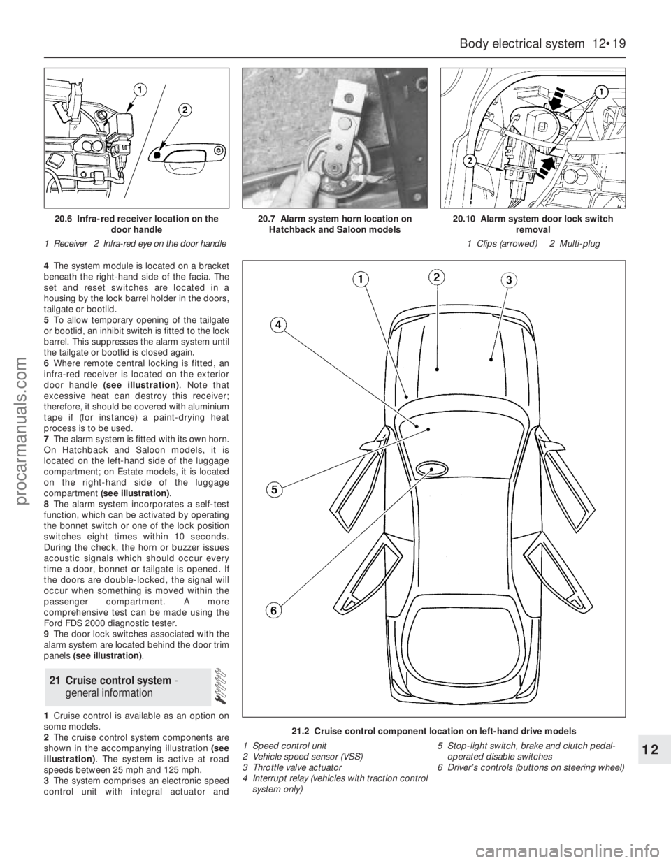
6Where remote central locking is fitted, an
infra-red receiver is located on the exterior
door handle (see illustration). Note that
excessive heat can destroy this receiver;
therefore, it should be covered with aluminium
tape if (for instance) a paint-drying heat
process is to be used.
7The alarm system is fitted with its own horn.
On Hatchback and Saloon models, it is
located on the left-hand side of the luggage
compartment; on Estate models, it is located
on the right-hand side of the luggage
compartment (see illustration).
8The alarm system incorporates a self-test
function, which can be activated by operating
the bonnet switch or one of the lock position
switches eight times within 10 seconds.
During the check, the horn or buzzer issues
acoustic signals which should occur every
time a door, bonnet or tailgate is opened. If
the doors are double-locked, the signal will
occur when something is moved within the
passenger compartment. A more
comprehensive test can be made using the
Ford FDS 2000 diagnostic tester.
9The door lock switches associated with the
alarm system are located behind the door trim
panels (see illustration).
1Cruise control is available as an option on
some models.
2The cruise control system components are
shown in the accompanying illustration (see
illustration). The system is active at road
speeds between 25 mph and 125 mph.
3The system comprises an electronic speed
control unit with integral actuator and
21 Cruise control system -
general information
Body electrical system 12•19
12
21.2 Cruise control component location on left-hand drive models
1 Speed control unit
2 Vehicle speed sensor (VSS)
3 Throttle valve actuator
4 Interrupt relay (vehicles with traction control
system only)5 Stop-light switch, brake and clutch pedal-
operated disable switches
6 Driver’s controls (buttons on steering wheel)
20.6 Infra-red receiver location on the
door handle
1 Receiver 2 Infra-red eye on the door handle20.7 Alarm system horn location on
Hatchback and Saloon models20.10 Alarm system door lock switch
removal
1 Clips (arrowed) 2 Multi-plug
procarmanuals.com
Page 222 of 279
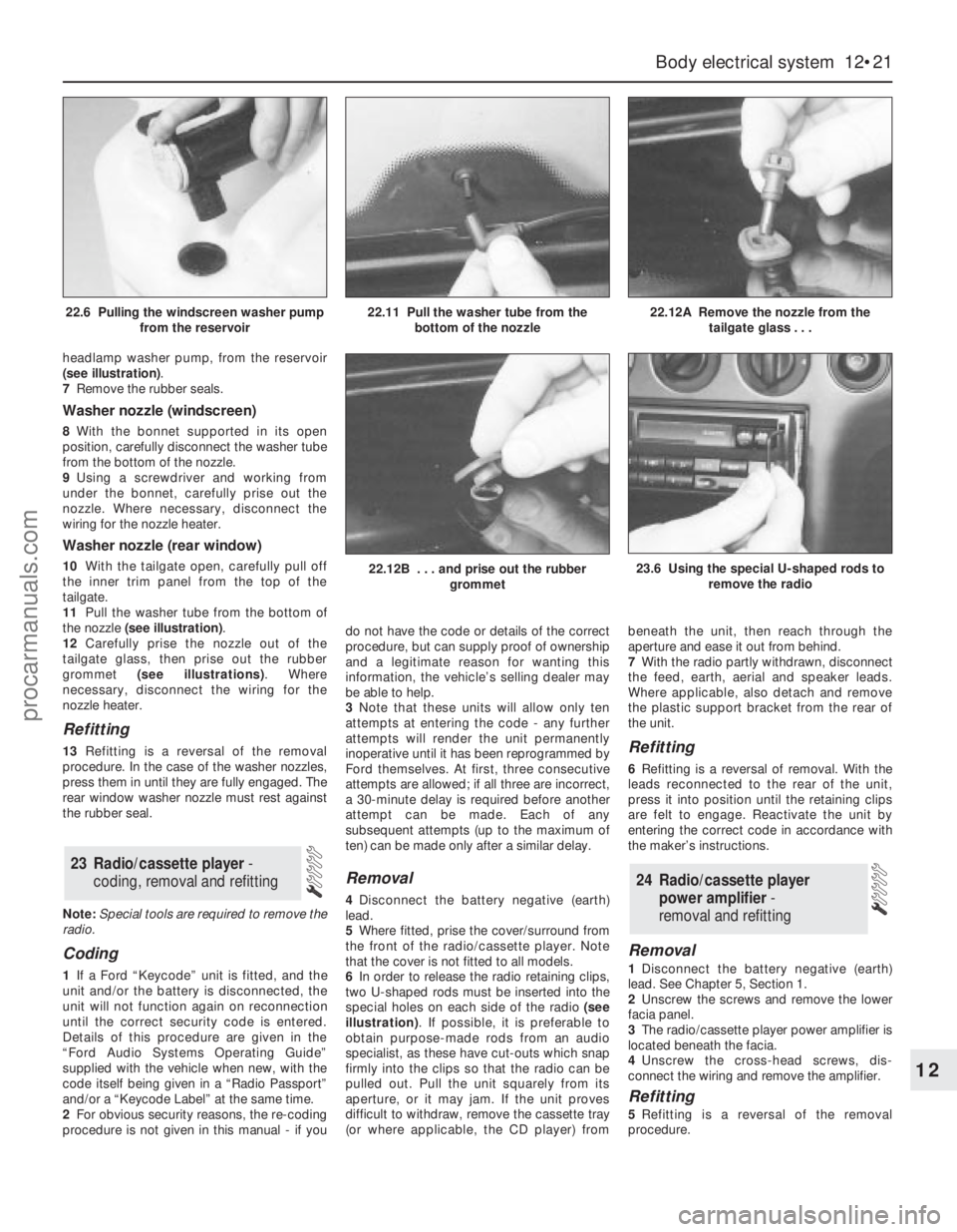
headlamp washer pump, from the reservoir
(see illustration).
7Remove the rubber seals.
Washer nozzle (windscreen)
8With the bonnet supported in its open
position, carefully disconnect the washer tube
from the bottom of the nozzle.
9Using a screwdriver and working from
under the bonnet, carefully prise out the
nozzle. Where necessary, disconnect the
wiring for the nozzle heater.
Washer nozzle (rear window)
10With the tailgate open, carefully pull off
the inner trim panel from the top of the
tailgate.
11Pull the washer tube from the bottom of
the nozzle (see illustration).
12Carefully prise the nozzle out of the
tailgate glass, then prise out the rubber
grommet (see illustrations). Where
necessary, disconnect the wiring for the
nozzle heater.
Refitting
13Refitting is a reversal of the removal
procedure. In the case of the washer nozzles,
press them in until they are fully engaged. The
rear window washer nozzle must rest against
the rubber seal.
Note:Special tools are required to remove the
radio.
Coding
1If a Ford “Keycode” unit is fitted, and the
unit and/or the battery is disconnected, the
unit will not function again on reconnection
until the correct security code is entered.
Details of this procedure are given in the
“Ford Audio Systems Operating Guide”
supplied with the vehicle when new, with the
code itself being given in a “Radio Passport”
and/or a “Keycode Label” at the same time.
2For obvious security reasons, the re-coding
procedure is not given in this manual - if youdo not have the code or details of the correct
procedure, but can supply proof of ownership
and a legitimate reason for wanting this
information, the vehicle’s selling dealer may
be able to help.
3Note that these units will allow only ten
attempts at entering the code - any further
attempts will render the unit permanently
inoperative until it has been reprogrammed by
Ford themselves. At first, three consecutive
attempts are allowed; if all three are incorrect,
a 30-minute delay is required before another
attempt can be made. Each of any
subsequent attempts (up to the maximum of
ten) can be made only after a similar delay.
Removal
4Disconnect the battery negative (earth)
lead.
5Where fitted, prise the cover/surround from
the front of the radio/cassette player. Note
that the cover is not fitted to all models.
6In order to release the radio retaining clips,
two U-shaped rods must be inserted into the
special holes on each side of the radio (see
illustration). If possible, it is preferable to
obtain purpose-made rods from an audio
specialist, as these have cut-outs which snap
firmly into the clips so that the radio can be
pulled out. Pull the unit squarely from its
aperture, or it may jam. If the unit proves
difficult to withdraw, remove the cassette tray
(or where applicable, the CD player) frombeneath the unit, then reach through the
aperture and ease it out from behind.
7With the radio partly withdrawn, disconnect
the feed, earth, aerial and speaker leads.
Where applicable, also detach and remove
the plastic support bracket from the rear of
the unit.
Refitting
6Refitting is a reversal of removal. With the
leads reconnected to the rear of the unit,
press it into position until the retaining clips
are felt to engage. Reactivate the unit by
entering the correct code in accordance with
the maker’s instructions.
Removal
1Disconnect the battery negative (earth)
lead. See Chapter 5, Section 1.
2Unscrew the screws and remove the lower
facia panel.
3The radio/cassette player power amplifier is
located beneath the facia.
4Unscrew the cross-head screws, dis-
connect the wiring and remove the amplifier.
Refitting
5Refitting is a reversal of the removal
procedure.
24 Radio/cassette player
power amplifier -
removal and refitting
23 Radio/cassette player -
coding, removal and refitting
Body electrical system 12•21
12
22.12B . . . and prise out the rubber
grommet23.6 Using the special U-shaped rods to
remove the radio
22.6 Pulling the windscreen washer pump
from the reservoir22.11 Pull the washer tube from the
bottom of the nozzle22.12A Remove the nozzle from the
tailgate glass . . .
procarmanuals.com
Page 276 of 279
REF•17Index
A
A pillar trim - 11•20
ABS - 9•14
Accelerator cable - 4•4
Accelerator pedal - 4•5
Accumulator - 3•9
Acknowledgements - 0•4
Adaptive damping switch - 12•8
Aerial - 12•22
Air bag - 0•5, 1•22, 12•22
Air cleaner - 4•3, 6•19
Air conditioning - 1•15, 3•2, 3•8, 3•9, 6•11
Air distribution control - 3•8
Air induction system - 4•9
Air intake components - 4•3
Air mass meter - 4•3, 6•10, 6•11, 6•12
Air temperature warning sender unit -
12•18
Alarm - 11•17, 12•18
Alternator - 5•5, 5•6
Amplifier - 12•21
Anti-lock Braking System - 9•14
Anti-roll bar - 10•8, 10•12, 10•15
Anti-theft alarm system - 12•18
Antifreeze - 1•2, 1•22, 3•2
Asbestos - 0•5
ATF - 1•2
Automatic transmission- 1•11, 1•17,
2A•24, 2B•3, 2B•4, 6•11, 7B•1et seq,
12•11
Automatic transmission fault finding -
REF•10
Automatic transmission fluid - 1•2
Auxiliary drivebelt - 1•13
Auxiliary warning system - 12•17
B
B pillar trim - 11•20
Backfire - REF•8
Backrest - 11•18
Battery - 0•5, 1•8, 1•11, 5•2, 5•3
Battery fault - REF•12
Big-end bearings - 2B•18, 2B•21
Bleeding brakes - 9•12
Bleeding power steering - 10•21
Blower/air conditioning control - 3•8Body corrosion - 0•10
Body electrical system- 12•1et seq
Bodywork and fittings- 11•1et seq
Bonnet - 1•20, 11•5, 11•6
Booster battery (jump) starting - 0•12
Boot - 11•14, 11•15
Brake check - 1•19
Brake fluid - 1•2, 1•8, 1•26
Brake line check - 1•19
Braking system- 0•7, 0•8, 0•9, 1•20, 9•1et
seq
Braking system fault finding - REF•10
Brush renewal - 5•8
Bulb failure module - 12•18
Bulbs - 12•8, 12•11, 12•18
Bumpers - 11•4, 11•5
Burning - 0•5
C
C pillar trim - 11•20, 11•21
Cables - 4•4, 7B•2, 8•2, 9•16, 11•6, 12•15
Calipers - 9•4, 9•9
Camshaft - 2A•13, 2A•14, 6•11, 6•12
Cassette player - 12•21
Catalytic converter - 6•19
CD player - 12•22
Central locking system - 11•17
Central locking system fault - REF•12
Centre console - 11•21
Charcoal canister - 6•14
Charging - 1•12, 5•5
Check strap - 11•13
Clock - 12•11, 12•15
Clutch and driveshafts- 1•17, 1•20, 8•1et
seq
Clutch fault finding - REF•9
CO emissions (mixture) - 0•10
Coil spring - 10•15
Compact disc player - 12•22
Compression test - 2A•5
Compressor - 3•9
Condenser - 3•9
Connecting rods - 2B•12, 2B•17, 2B•21,
2B•22
Console - 11•21, 11•22
Contents - 0•2
Conversion factors - 0•14Coolant - 1•2, 1•6, 1•7, 1•21
Coolant leakage - REF•9
Coolant low level switch - 3•5
Coolant temperature gauge sender - 3•4
Coolant temperature sensor - 3•5, 6•11,
6•13
Coolant warning switch - 12•18
Cooling, heating, and air conditioning
systems- 1•22, 3•1et seq
Cooling, heating, and air conditioning
systems fault finding - REF•8
Corrosion - REF•9
Courtesy light - 12•8
Crankcase - 2B•13
Crankshaft - 2A•9, 2A•13, 2A•22, 2B•13,
2B•18, 2B•20, 5•4, 6•10, 6•11, 6•12
Crossmember - 10•13, 10•17
Cruise control system - 12•19
Crushing - 0•5
Cushion - 11•18
CV joints - 1•18, 8•7, 8•9
Cylinder block - 2B•13
Cylinder head - 2A•6, 2A•17, 2B•9, 2B•10,
2B•11, 6•19
D
D pillar trim - 11•21
Damping switch - 12•8
Dehydrator - 3•9
Dents in bodywork - 11•3
Depressurisation - 4•2
Diagnosis system - 6•4
Differential - 7A•2, 7B•3
Dimensions - 0•6
Dipped beam switch - 12•7
Direction indicators - 12•7, 12•9, 12•12
Discs - 1•19, 9•5, 9•10
Display warning bulb - 12•18
Doors - 0•8, 1•20, 11•6, 11•7, 11•8, 11•9,
11•10, 11•11, 11•13, 12•7, 12•8, 12•11,
12•18
Drivebelts - 1•13
Driveplate - 2A•24
Driveshafts - 0•9, 1•18, 8•5, 8•6, 8•7, 8•9,
8•10
Driveshafts fault finding - REF•10
Drivetrain - 1•20
Drums - 1•19, 9•6 Note: References throughout this index relate to Chapter•page number
procarmanuals.com