1993 FORD MONDEO length
[x] Cancel search: lengthPage 35 of 279
pleated-paper type filter, it cannot be washed
or re-oiled. If it cannot be cleaned
satisfactorily with compressed air, discard
and renew it.
Warning: Wear eye protection
when using compressed air!
8Refitting is the reverse of the removal
procedure; ensure that the element and
housing are securely seated, so that unfiltered
air cannot enter the passenger compartment.
Note:If the antifreeze used is Ford’s own, or of
similar quality, the coolant need not be
renewed for the life of the vehicle. If the
vehicle’s history is unknown, if antifreeze of
lesser quality is known to be in the system, or
simply if you prefer to follow conventional
servicing intervals, the coolant should be
changed periodically (typically, every 2 years)
as described here. Refer also to the
information in Section 2 of this Chapter.
Warning: Do not allow antifreeze
to come in contact with your skin
or painted surfaces of the
vehicle. Flush contaminated areas
immediately with plenty of water. Don’t
store new coolant, or leave old coolant
lying around, where it’s accessible to
children or pets - they’re attracted by its
sweet smell. Ingestion of even a small
amount of coolant can be fatal! Wipe up
garage-floor and drip-pan spills
immediately. Keep antifreeze containers
covered, and repair cooling system leaks
as soon as they’re noticed.
Warning: Never remove the
expansion tank filler cap when
the engine is running, or has just
been switched off, as the cooling system
will be hot, and the consequent escaping
steam and scalding coolant could cause
serious injury.
Coolant draining
Warning: Wait until the engine is
cold before starting this
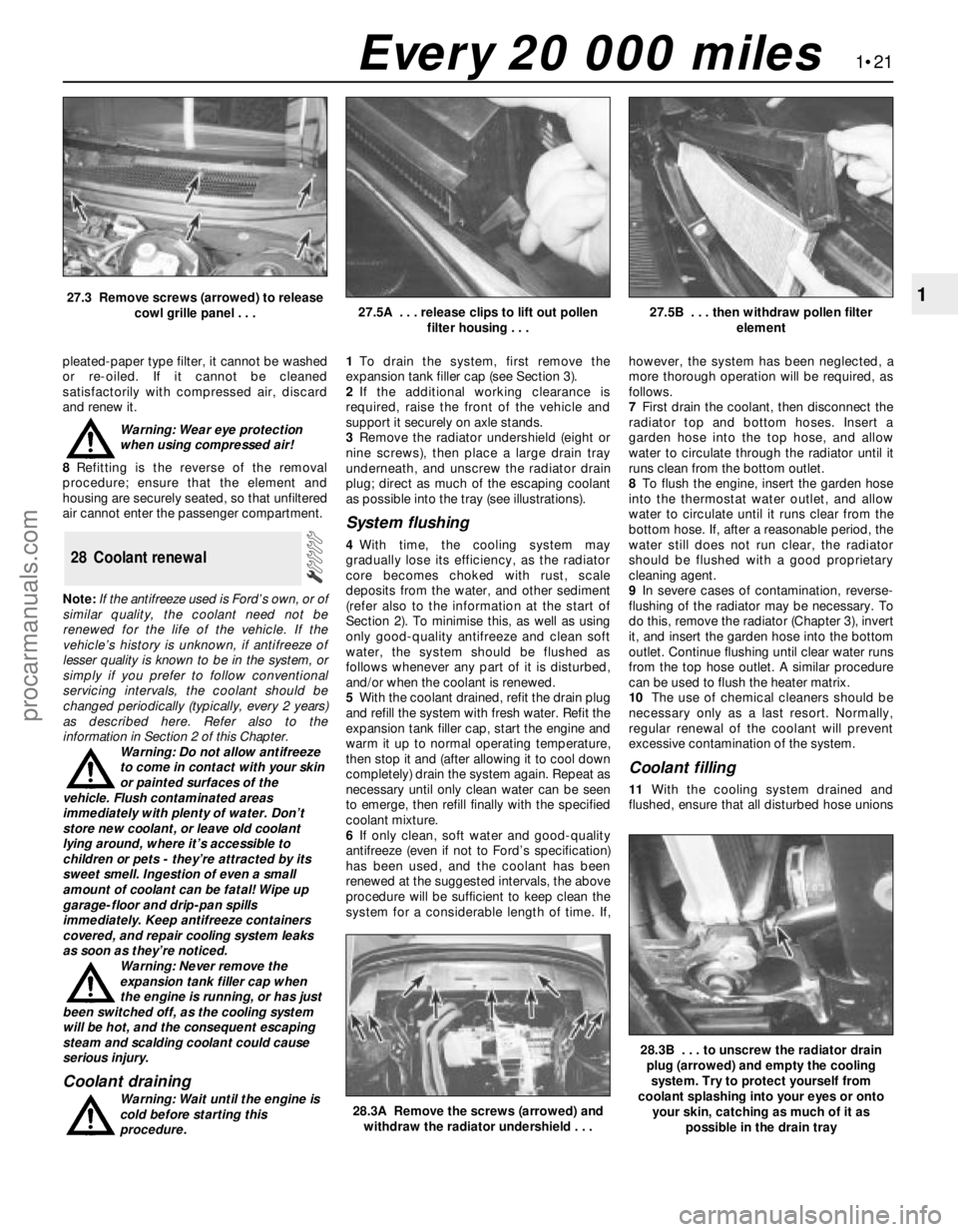
procedure.1To drain the system, first remove the
expansion tank filler cap (see Section 3).
2If the additional working clearance is
required, raise the front of the vehicle and
support it securely on axle stands.
3Remove the radiator undershield (eight or
nine screws), then place a large drain tray
underneath, and unscrew the radiator drain
plug; direct as much of the escaping coolant
as possible into the tray (see illustrations).
System flushing
4With time, the cooling system may
gradually lose its efficiency, as the radiator
core becomes choked with rust, scale
deposits from the water, and other sediment
(refer also to the information at the start of
Section 2). To minimise this, as well as using
only good-quality antifreeze and clean soft
water, the system should be flushed as
follows whenever any part of it is disturbed,
and/or when the coolant is renewed.
5With the coolant drained, refit the drain plug
and refill the system with fresh water. Refit the
expansion tank filler cap, start the engine and
warm it up to normal operating temperature,
then stop it and (after allowing it to cool down
completely) drain the system again. Repeat as
necessary until only clean water can be seen
to emerge, then refill finally with the specified
coolant mixture.
6If only clean, soft water and good-quality
antifreeze (even if not to Ford’s specification)
has been used, and the coolant has been
renewed at the suggested intervals, the above
procedure will be sufficient to keep clean the
system for a considerable length of time. If,however, the system has been neglected, a
more thorough operation will be required, as
follows.
7First drain the coolant, then disconnect the
radiator top and bottom hoses. Insert a
garden hose into the top hose, and allow
water to circulate through the radiator until it
runs clean from the bottom outlet.
8To flush the engine, insert the garden hose
into the thermostat water outlet, and allow
water to circulate until it runs clear from the
bottom hose. If, after a reasonable period, the
water still does not run clear, the radiator
should be flushed with a good proprietary
cleaning agent.
9In severe cases of contamination, reverse-
flushing of the radiator may be necessary. To
do this, remove the radiator (Chapter 3), invert
it, and insert the garden hose into the bottom
outlet. Continue flushing until clear water runs
from the top hose outlet. A similar procedure
can be used to flush the heater matrix.
10The use of chemical cleaners should be
necessary only as a last resort. Normally,
regular renewal of the coolant will prevent
excessive contamination of the system.
Coolant filling
11With the cooling system drained and
flushed, ensure that all disturbed hose unions
28 Coolant renewal
1•21
1
28.3A Remove the screws (arrowed) and
withdraw the radiator undershield . . .
28.3B . . . to unscrew the radiator drain
plug (arrowed) and empty the cooling
system. Try to protect yourself from
coolant splashing into your eyes or onto
your skin, catching as much of it as
possible in the drain tray
27.3 Remove screws (arrowed) to release
cowl grille panel . . .27.5A . . . release clips to lift out pollen
filter housing . . .27.5B . . . then withdraw pollen filter
element
Every 20 000 miles
procarmanuals.com
Page 36 of 279
are correctly secured, and that the radiator
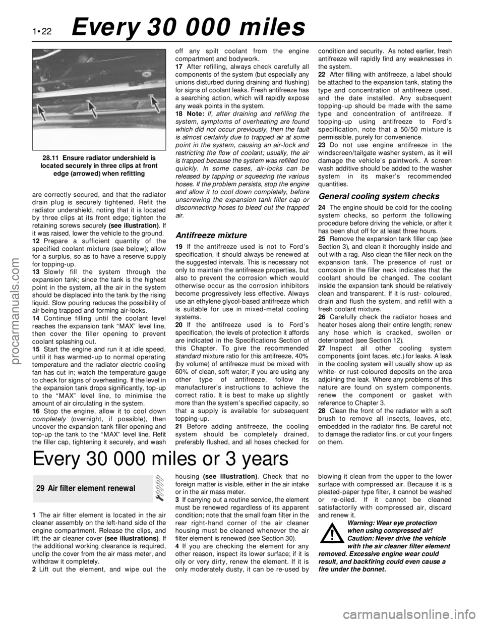
drain plug is securely tightened. Refit the
radiator undershield, noting that it is located
by three clips at its front edge; tighten the
retaining screws securely (see illustration). If
it was raised, lower the vehicle to the ground.
12Prepare a sufficient quantity of the
specified coolant mixture (see below); allow
for a surplus, so as to have a reserve supply
for topping-up.
13Slowly fill the system through the
expansion tank; since the tank is the highest
point in the system, all the air in the system
should be displaced into the tank by the rising
liquid. Slow pouring reduces the possibility of
air being trapped and forming air-locks.
14Continue filling until the coolant level
reaches the expansion tank “MAX” level line,
then cover the filler opening to prevent
coolant splashing out.
15Start the engine and run it at idle speed,
until it has warmed-up to normal operating
temperature and the radiator electric cooling
fan has cut in; watch the temperature gauge
to check for signs of overheating. If the level in
the expansion tank drops significantly, top-up
to the “MAX” level line, to minimise the
amount of air circulating in the system.
16Stop the engine, allow it to cool down
completely(overnight, if possible), then
uncover the expansion tank filler opening and
top-up the tank to the “MAX” level line. Refit
the filler cap, tightening it securely, and washoff any spilt coolant from the engine
compartment and bodywork.
17After refilling, always check carefully all
components of the system (but especially any
unions disturbed during draining and flushing)
for signs of coolant leaks. Fresh antifreeze has
a searching action, which will rapidly expose
any weak points in the system.
18 Note:If, after draining and refilling the
system, symptoms of overheating are found
which did not occur previously, then the fault
is almost certainly due to trapped air at some
point in the system, causing an air-lock and
restricting the flow of coolant; usually, the air
is trapped because the system was refilled too
quickly. In some cases, air-locks can be
released by tapping or squeezing the various
hoses. If the problem persists, stop the engine
and allow it to cool down completely, before
unscrewing the expansion tank filler cap or
disconnecting hoses to bleed out the trapped
air.
Antifreeze mixture
19If the antifreeze used is not to Ford’s
specification, it should always be renewed at
the suggested intervals. This is necessary not
only to maintain the antifreeze properties, but
also to prevent the corrosion which would
otherwise occur as the corrosion inhibitors
become progressively less effective. Always
use an ethylene glycol-based antifreeze which
is suitable for use in mixed-metal cooling
systems.
20If the antifreeze used is to Ford’s
specification, the levels of protection it affords
are indicated in the Specifications Section of
this Chapter. To give the recommended
standardmixture ratio for this antifreeze, 40%
(by volume) of antifreeze must be mixed with
60% of clean, soft water; if you are using any
other type of antifreeze, follow its
manufacturer’s instructions to achieve the
correct ratio. It is best to make up slightly
more than the system’s specified capacity, so
that a supply is available for subsequent
topping-up.
21Before adding antifreeze, the cooling
system should be completely drained,
preferably flushed, and all hoses checked forcondition and security. As noted earlier, fresh
antifreeze will rapidly find any weaknesses in
the system.
22After filling with antifreeze, a label should
be attached to the expansion tank, stating the
type and concentration of antifreeze used,
and the date installed. Any subsequent
topping-up should be made with the same
type and concentration of antifreeze. If
topping-up using antifreeze to Ford’s
specification, note that a 50/50 mixture is
permissible, purely for convenience.
23Do not use engine antifreeze in the
windscreen/tailgate washer system, as it will
damage the vehicle’s paintwork. A screen
wash additive should be added to the washer
system in its maker’s recommended
quantities.
General cooling system checks
24The engine should be cold for the cooling
system checks, so perform the following
procedure before driving the vehicle, or after it
has been shut off for at least three hours.
25Remove the expansion tank filler cap (see
Section 3), and clean it thoroughly inside and
out with a rag. Also clean the filler neck on the
expansion tank. The presence of rust or
corrosion in the filler neck indicates that the
coolant should be changed. The coolant
inside the expansion tank should be relatively
clean and transparent. If it is rust- coloured,
drain and flush the system, and refill with a
fresh coolant mixture.
26Carefully check the radiator hoses and
heater hoses along their entire length; renew
any hose which is cracked, swollen or
deteriorated (see Section 12).
27Inspect all other cooling system
components (joint faces, etc.) for leaks. A leak
in the cooling system will usually show up as
white- or rust-coloured deposits on the area
adjoining the leak. Where any problems of this
nature are found on system components,
renew the component or gasket with
reference to Chapter 3.
28Clean the front of the radiator with a soft
brush to remove all insects, leaves, etc,
embedded in the radiator fins. Be careful not
to damage the radiator fins, or cut your fingers
on them.
1•22
28.11 Ensure radiator undershield is
located securely in three clips at front
edge (arrowed) when refitting
Every 30 000 miles
Every 30 000 miles or 3 years
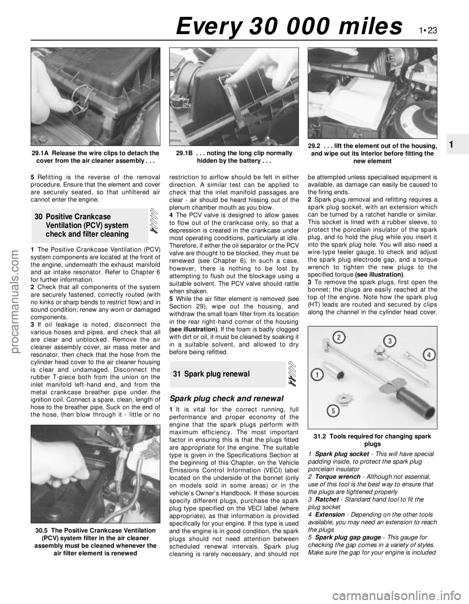
1The air filter element is located in the air
cleaner assembly on the left-hand side of the
engine compartment. Release the clips, and
lift the air cleaner cover (see illustrations). If
the additional working clearance is required,
unclip the cover from the air mass meter, and
withdraw it completely.
2Lift out the element, and wipe out thehousing (see illustration). Check that no
foreign matter is visible, either in the air intake
or in the air mass meter.
3If carrying out a routine service, the element
must be renewed regardless of its apparent
condition; note that the small foam filter in the
rear right-hand corner of the air cleaner
housing must be cleaned whenever the air
filter element is renewed (see Section 30).
4If you are checking the element for any
other reason, inspect its lower surface; if it is
oily or very dirty, renew the element. If it is
only moderately dusty, it can be re-used byblowing it clean from the upper to the lower
surface with compressed air. Because it is a
pleated-paper type filter, it cannot be washed
or re-oiled. If it cannot be cleaned
satisfactorily with compressed air, discard
and renew it.
Warning: Wear eye protection
when using compressed air!
Caution: Never drive the vehicle
with the air cleaner filter element
removed. Excessive engine wear could
result, and backfiring could even cause a
fire under the bonnet.
29 Air filter element renewal
procarmanuals.com
Page 37 of 279
5Refitting is the reverse of the removal
procedure. Ensure that the element and cover
are securely seated, so that unfiltered air
cannot enter the engine.
1The Positive Crankcase Ventilation (PCV)
system components are located at the front of
the engine, underneath the exhaust manifold
and air intake resonator. Refer to Chapter 6
for further information.
2Check that all components of the system
are securely fastened, correctly routed (with
no kinks or sharp bends to restrict flow) and in
sound condition; renew any worn or damaged
components.
3If oil leakage is noted, disconnect the
various hoses and pipes, and check that all
are clear and unblocked. Remove the air
cleaner assembly cover, air mass meter and
resonator, then check that the hose from the
cylinder head cover to the air cleaner housing
is clear and undamaged. Disconnect the
rubber T-piece both from the union on the
inlet manifold left-hand end, and from the
metal crankcase breather pipe under the
ignition coil. Connect a spare, clean, length of
hose to the breather pipe. Suck on the end of
the hose, then blow through it - little or norestriction to airflow should be felt in either
direction. A similar test can be applied to
check that the inlet manifold passages are
clear - air should be heard hissing out of the
plenum chamber mouth as you blow.
4The PCV valve is designed to allow gases
to flow out of the crankcase only, so that a
depression is created in the crankcase under
most operating conditions, particularly at idle.
Therefore, if either the oil separator or the PCV
valve are thought to be blocked, they must be
renewed (see Chapter 6). In such a case,
however, there is nothing to be lost by
attempting to flush out the blockage using a
suitable solvent. The PCV valve should rattle
when shaken.
5While the air filter element is removed (see
Section 29), wipe out the housing, and
withdraw the small foam filter from its location
in the rear right-hand corner of the housing
(see illustration). If the foam is badly clogged
with dirt or oil, it must be cleaned by soaking it
in a suitable solvent, and allowed to dry
before being refitted.
Spark plug check and renewal
1It is vital for the correct running, full
performance and proper economy of the
engine that the spark plugs perform with
maximum efficiency. The most important
factor in ensuring this is that the plugs fitted
are appropriate for the engine. The suitable
type is given in the Specifications Section at
the beginning of this Chapter, on the Vehicle
Emissions Control Information (VECI) label
located on the underside of the bonnet (only
on models sold in some areas) or in the
vehicle’s Owner’s Handbook. If these sources
specify different plugs, purchase the spark
plug type specified on the VECI label (where
appropriate), as that information is provided
specifically for your engine. If this type is used
and the engine is in good condition, the spark
plugs should not need attention between
scheduled renewal intervals. Spark plug
cleaning is rarely necessary, and should notbe attempted unless specialised equipment is
available, as damage can easily be caused to
the firing ends.
2Spark plug removal and refitting requires a
spark plug socket, with an extension which
can be turned by a ratchet handle or similar.
This socket is lined with a rubber sleeve, to
protect the porcelain insulator of the spark
plug, and to hold the plug while you insert it
into the spark plug hole. You will also need a
wire-type feeler gauge, to check and adjust
the spark plug electrode gap, and a torque
wrench to tighten the new plugs to the
specified torque (see illustration).
3To remove the spark plugs, first open the
bonnet; the plugs are easily reached at the
top of the engine. Note how the spark plug
(HT) leads are routed and secured by clips
along the channel in the cylinder head cover.
31 Spark plug renewal
30 Positive Crankcase
Ventilation (PCV) system
check and filter cleaning
1•23
1
30.5 The Positive Crankcase Ventilation
(PCV) system filter in the air cleaner
assembly must be cleaned whenever the
air filter element is renewed
31.2 Tools required for changing spark
plugs
1Spark plug socket- This will have special
padding inside, to protect the spark plug
porcelain insulator
2Torque wrench- Although not essential,
use of this tool is the best way to ensure that
the plugs are tightened properly
3Ratchet- Standard hand tool to fit the
plug socket
4Extension- Depending on the other tools
available, you may need an extension to reach
the plugs
5Spark plug gap gauge- This gauge for
checking the gap comes in a variety of styles.
Make sure the gap for your engine is included
29.1A Release the wire clips to detach the
cover from the air cleaner assembly . . .29.1B . . . noting the long clip normally
hidden by the battery . . .29.2 . . . lift the element out of the housing,
and wipe out its interior before fitting the
new element
Every 30 000 miles
procarmanuals.com
Page 39 of 279
check the cylinder head threads and tapered
sealing surfaces for signs of wear, excessive
corrosion or damage; if any of these
conditions is found, seek the advice of a Ford
dealer as to the best method of repair.
7As each plug is removed, examine it as
follows - this will give a good indication of the
condition of the engine. If the insulator nose of
the spark plug is clean and white, with no
deposits, this is indicative of a weak mixture.
8If the tip and insulator nose are covered
with hard black-looking deposits, then this is
indicative that the mixture is too rich. Should
the plug be black and oily, then it is likely that
the engine is fairly worn, as well as the mixture
being too rich.
9If the insulator nose is covered with light tan
to greyish-brown deposits, then the mixture is
correct, and it is likely that the engine is in
good condition.
10If you are renewing the spark plugs,
purchase the new plugs, then check each of
them first for faults such as cracked insulators
or damaged threads. Note also that,
whenever the spark plugs are renewed as a
routine service operation, the spark plug (HT)
leads should be checked as described below.
11The spark plug electrode gap is of
considerable importance as, if it is too large or
too small, the size of the spark and its
efficiency will be seriously impaired. The gap
should be set to the value given in the
Specifications Section of this Chapter. New
plugs will not necessarily be set to the correct
gap, so they should always be checked
before fitting.
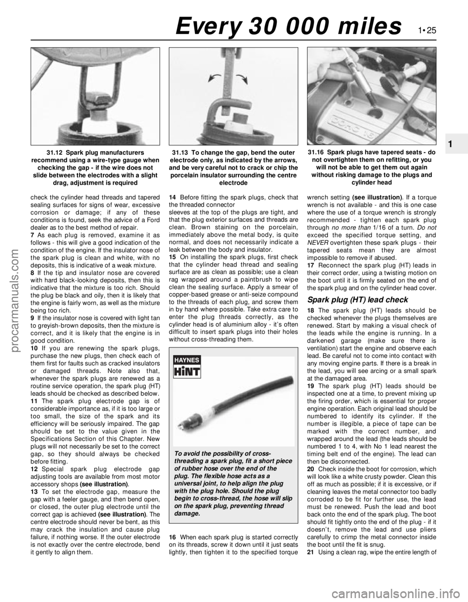
12Special spark plug electrode gap
adjusting tools are available from most motor
accessory shops (see illustration).
13To set the electrode gap, measure the
gap with a feeler gauge, and then bend open,
or closed, the outer plug electrode until the
correct gap is achieved (see illustration). The
centre electrode should never be bent, as this
may crack the insulation and cause plug
failure, if nothing worse. If the outer electrode
is not exactly over the centre electrode, bend
it gently to align them.14Before fitting the spark plugs, check that
the threaded connector
sleeves at the top of the plugs are tight, and
that the plug exterior surfaces and threads are
clean. Brown staining on the porcelain,
immediately above the metal body, is quite
normal, and does not necessarily indicate a
leak between the body and insulator.
15On installing the spark plugs, first check
that the cylinder head thread and sealing
surface are as clean as possible; use a clean
rag wrapped around a paintbrush to wipe
clean the sealing surface. Apply a smear of
copper-based grease or anti-seize compound
to the threads of each plug, and screw them
in by hand where possible. Take extra care to
enter the plug threads correctly, as the
cylinder head is of aluminium alloy - it’s often
difficult to insert spark plugs into their holes
without cross-threading them.
16When each spark plug is started correctly
on its threads, screw it down until it just seats
lightly, then tighten it to the specified torquewrench setting (see illustration). If a torque
wrench is not available - and this is one case
where the use of a torque wrench is strongly
recommended - tighten each spark plug
through no more than1/16 of a turn. Do not
exceed the specified torque setting, and
NEVERovertighten these spark plugs - their
tapered seats mean they are almost
impossible to remove if abused.
17Reconnect the spark plug (HT) leads in
their correct order, using a twisting motion on
the boot until it is firmly seated on the end of
the spark plug and on the cylinder head cover.
Spark plug (HT) lead check
18The spark plug (HT) leads should be
checked whenever the plugs themselves are
renewed. Start by making a visual check of
the leads while the engine is running. In a
darkened garage (make sure there is
ventilation) start the engine and observe each
lead. Be careful not to come into contact with
any moving engine parts. If there is a break in
the lead, you will see arcing or a small spark
at the damaged area.
19The spark plug (HT) leads should be
inspected one at a time, to prevent mixing up
the firing order, which is essential for proper
engine operation. Each original lead should be
numbered to identify its cylinder. If the
number is illegible, a piece of tape can be
marked with the correct number, and
wrapped around the lead (the leads should be
numbered 1 to 4, with No 1 lead nearest the
timing belt end of the engine). The lead can
then be disconnected.
20Check inside the boot for corrosion, which
will look like a white crusty powder. Clean this
off as much as possible; if it is excessive, or if
cleaning leaves the metal connector too badly
corroded to be fit for further use, the lead
must be renewed. Push the lead and boot
back onto the end of the spark plug. The boot
should fit tightly onto the end of the plug - if it
doesn’t, remove the lead and use pliers
carefully to crimp the metal connector inside
the boot until the fit is snug.
21Using a clean rag, wipe the entire length of
1•25
1
Every 30 000 miles
31.12 Spark plug manufacturers
recommend using a wire-type gauge when
checking the gap - if the wire does not
slide between the electrodes with a slight
drag, adjustment is required31.13 To change the gap, bend the outer
electrode only, as indicated by the arrows,
and be very careful not to crack or chip the
porcelain insulator surrounding the centre
electrode31.16 Spark plugs have tapered seats - do
not overtighten them on refitting, or you
will not be able to get them out again
without risking damage to the plugs and
cylinder head
To avoid the possibility of cross-
threading a spark plug, fit a short piece
of rubber hose over the end of the
plug. The flexible hose acts as a
universal joint, to help align the plug
with the plug hole. Should the plug
begin to cross-thread, the hose will slip
on the spark plug, preventing thread
damage.
procarmanuals.com
Page 46 of 279
specifications were available from Ford, but a
typical reading would be in excess of 12 bars.
All cylinders should produce very similar
pressures; any difference greater than 10%
indicates the existence of a fault. Note that the
compression should build up quickly in a
healthy engine; low compression on the first
stroke, followed by gradually-increasing
pressure on successive strokes, indicates worn
piston rings. A low compression reading on the
first stroke, which does not build up during
successive strokes, indicates leaking valves or a
blown head gasket (a cracked head could also
be the cause). Deposits on the undersides of the
valve heads can also cause low compression.
8If the pressure in any cylinder is
considerably lower than the others, introduce
a teaspoonful of clean oil into that cylinder
through its spark plug hole, and repeat the
test.
9If the addition of oil temporarily improves
the compression pressure, this indicates that
bore or piston wear is responsible for the
pressure loss. No improvement suggests that
leaking or burnt valves, or a blown head
gasket, may be to blame.
10A low reading from two adjacent cylinders
is almost certainly due to the head gasket
having blown between them; the presence of
coolant in the engine oil will confirm this.
11If one cylinder is about 20 percent lower
than the others and the engine has a slightly
rough idle, a worn camshaft lobe or faulty
hydraulic tappet could be the cause.
12If the compression is unusually high, the
combustion chambers are probably coated
with carbon deposits. If this is the case, the
cylinder head should be removed and
decarbonised.
13On completion of the test, refit the spark
plugs, then reconnect the ignition system and
fuel pump.
General
1Top Dead Centre (TDC) is the highest point
in its travel up-and-down its cylinder bore
that each piston reaches as the crankshaftrotates. While each piston reaches TDC both
at the top of the compression stroke and
again at the top of the exhaust stroke, for the
purpose of timing the engine, TDC refers to
the piston position (usually No 1 piston) at the
top of its compression stroke.
2It is useful for several servicing procedures
to be able to position the engine at TDC.
3No 1 piston and cylinder are at the right-
hand (timing belt) end of the engine (right-
and left-hand are always quoted as seen from
the driver’s seat). Note that the crankshaft
rotates clockwise when viewed from the
right-hand side of the vehicle.
Locating TDC
4Remove all the spark plugs (Chapter 1).
5Disconnect both battery leads - see
Chapter 5, Section 1 - unless the starter
motor is to be used to turn the engine.
6Apply the handbrake and ensure that the
transmission is in neutral, then jack up the
front right-hand side of the vehicle and
support on an axle stand. Remove the
roadwheel.
7Remove the auxiliary drivebelt cover (see
Chapter 1) to expose the crankshaft pulley
and timing marks.
8It is best to rotate the crankshaft using a
spanner applied to the crankshaft pulley bolt;
however, it is possible also to use the starter
motor (switched on either by an assistant
using the ignition key, or by using a remote
starter switch) to bring the engine close to
TDC, then finish with a spanner. If the starter
is used, be sure to disconnect the battery
leads immediately it is no longer required.
9Note the two pairs of notches in the inner
and outer rims of the crankshaft pulley. In the
normal direction of crankshaft rotation
(clockwise, seen from the right-hand side of the
vehicle) the first pair of notches are irrelevant to
the vehicles covered in this manual, while the
second pair indicate TDC when aligned with
the rear edge of the raised mark on the sump.
Rotate the crankshaft clockwise until the
second pair of notches align with the edge of
the sump mark; use a straight edge extended
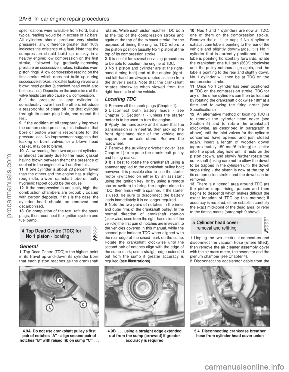
out from the sump if greater accuracy is
required (see illustrations).10Nos 1 and 4 cylinders are now at TDC,
one of them on the compression stroke.
Remove the oil filler cap; if No 4 cylinder
exhaust cam lobe is pointing to the rear of the
vehicle and slightly downwards, it is No 1
cylinder that is correctly positioned. If the
lobe is pointing horizontally forwards, rotate
the crankshaft one full turn (360°) clockwise
until the pulley notches align again, and the
lobe is pointing to the rear and slightly down.
No 1 cylinder will then be at TDC on the
compression stroke.
11Once No 1 cylinder has been positioned
at TDC on the compression stroke, TDC for
any of the other cylinders can then be located
by rotating the crankshaft clockwise 180° at a
time and following the firing order (see
Specifications).
12An alternative method of locating TDC is
to remove the cylinder head cover (see
Section 5) and to rotate the crankshaft
(clockwise, as described in paragraph 8
above) until the inlet valves for the cylinder
concerned have opened and just closed
again. Insert a length of wooden dowel
(approximately 150 mm/6 in long) or similar
into the spark plug hole until it rests on the
piston crown, and slowly further rotate the
crankshaft (taking care not to allow the dowel
to be trapped in the cylinder) until the dowel
stops rising - the piston is now at the top of
its compression stroke, and the dowel can be
removed.
13There is a “dead” area around TDC (as
the piston stops rising, pauses and then
begins to descend) which makes difficult the
exact location of TDC by this method; if
accuracy is required, either establish carefully
the exact mid-point of the dead area, or refer
to the timing marks (paragraph 9 above).
1Unplug the two electrical connectors and
disconnect the vacuum hose (where fitted),
then remove the air cleaner assembly cover
with the air mass meter, the resonator and the
plenum chamber (see Chapter 4).
2Disconnect the accelerator cable from the
5 Cylinder head cover-
removal and refitting
4 Top Dead Centre (TDC) for
No 1 piston - locating
2A•6 In-car engine repair procedures
4.9A Do not use crankshaft pulley’s first
pair of notches “A” - align second pair of
notches “B” with raised rib on sump “C” . . .4.9B . . . using a straight edge extended
out from the sump (arrowed) if greater
accuracy is required5.4 Disconnecting crankcase breather
hose from cylinder head cover union
procarmanuals.com
Page 51 of 279
1With the vehicle parked on firm level
ground, open the bonnet and disconnect the
battery negative (earth) lead - see Chapter 5,
Section 1 (see illustration).
2Unbolt the power steering high-pressure
pipe from the cylinder head rear support
plate/engine lifting eye, and from the front
support plate/pump bracket.
3Unscrew the six nuts securing the
engine/transmission right-hand mounting
bracket, then withdraw the bracket.
4Slacken the water pump pulley bolts.5Remove the cylinder head cover (see
Section 5).
6Remove the spark plugs, covering their
holes with clean rag, to prevent dirt or other
foreign bodies from dropping in (see Chap-
ter 1).
7Remove the auxiliary drivebelt (see Chap-
ter 1).
8Rotate the crankshaft clockwise until the
second pair of notches in the pulley rim align
with the edge of the sump mark, so that Nos
1 and 4 cylinders are at TDC (see Section 4).9Unbolt and remove the water pump pulley
and the auxiliary drivebelt idler pulley.
10Obtain Ford service tool 21-162, or
fabricate a substitute from a strip of metal
5 mm thick (while the strip’s thickness is
critical, its length and width are not, but
should be approximately 180 to 230 mm by
20 to 30 mm). Check that Nos 1 and 4
cylinders are at Top Dead Centre (TDC) - No 1
on the compression stroke - by resting this
tool on the cylinder head mating surface, and
sliding it into the slot in the left-hand end of
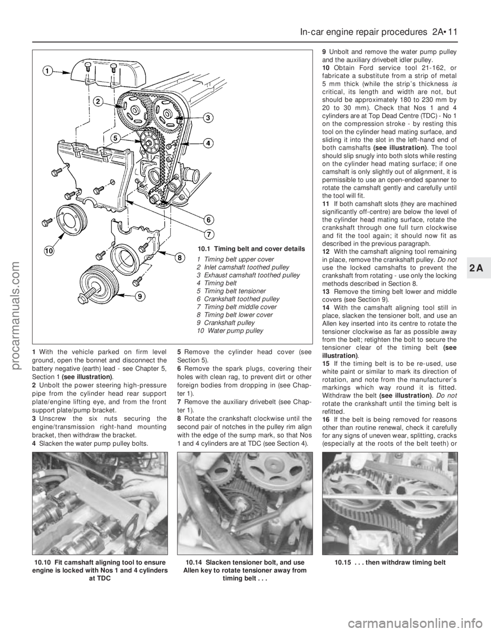
both camshafts (see illustration). The tool
should slip snugly into both slots while resting
on the cylinder head mating surface; if one
camshaft is only slightly out of alignment, it is
permissible to use an open-ended spanner to
rotate the camshaft gently and carefully until
the tool will fit.
11If both camshaft slots (they are machined
significantly off-centre) are below the level of
the cylinder head mating surface, rotate the
crankshaft through one full turn clockwise
and fit the tool again; it should now fit as
described in the previous paragraph.
12With the camshaft aligning tool remaining
in place, remove the crankshaft pulley. Do not
use the locked camshafts to prevent the
crankshaft from rotating - use only the locking
methods described in Section 8.
13Remove the timing belt lower and middle
covers (see Section 9).
14With the camshaft aligning tool still in
place, slacken the tensioner bolt, and use an
Allen key inserted into its centre to rotate the
tensioner clockwise as far as possible away
from the belt; retighten the bolt to secure the
tensioner clear of the timing belt (see
illustration).
15If the timing belt is to be re-used, use
white paint or similar to mark its direction of
rotation, and note from the manufacturer’s
markings which way round it is fitted.
Withdraw the belt (see illustration). Do not
rotate the crankshaft until the timing belt is
refitted.
16If the belt is being removed for reasons
other than routine renewal, check it carefully
for any signs of uneven wear, splitting, cracks
(especially at the roots of the belt teeth) or
In-car engine repair procedures 2A•11
2A
10.10 Fit camshaft aligning tool to ensure
engine is locked with Nos 1 and 4 cylinders
at TDC10.14 Slacken tensioner bolt, and use
Allen key to rotate tensioner away from
timing belt . . .10.15 . . . then withdraw timing belt
10.1 Timing belt and cover details
1 Timing belt upper cover
2 Inlet camshaft toothed pulley
3 Exhaust camshaft toothed pulley
4 Timing belt
5 Timing belt tensioner
6 Crankshaft toothed pulley
7 Timing belt middle cover
8 Timing belt lower cover
9 Crankshaft pulley
10 Water pump pulley
procarmanuals.com
Page 52 of 279
contamination with oil or coolant. Renew the
belt if there is the slightest doubt about its
condition. As a safety measure, the belt must
be renewed as a matter of course at the
intervals given in Chapter 1; if its history is
unknown, the belt should be renewed
irrespective of its apparent condition
whenever the engine is overhauled. Similarly,
check the tensioner spring (where fitted),
renewing it if there is any doubt about its
condition. Check also the toothed pulleys for
signs of wear or damage, and ensure that the
tensioner and guide pulleys rotate smoothly
on their bearings; renew any worn or
damaged components. If signs of oil or
coolant contamination are found, trace the
source of the leak and rectify it, then wash
down the engine timing belt area and related
components, to remove all traces of oil or
coolant.
17On reassembly, temporarily refit the
crankshaft pulley, to check that the pulley
notches and sump rib are aligned as
described in paragraph 8 above, then ensure
that both camshafts are aligned at TDC by
the special tool (paragraph 10). If the engine
is being reassembled after major dismantling,
both camshaft toothed pulleys should be free
to rotate on their respective camshafts; if the
timing belt alone is being renewed, both
pulleys should still be securely fastened.
18A holding tool will be required to prevent
the camshaft toothed pulleys from rotating
while their bolts are slackened and
retightened; either obtain Ford service tool15-030A, or fabricate a substitute as follows.
Find two lengths of steel strip, one
approximately 600 mm long and the other
about 200 mm, and three bolts with nuts and
washers; one nut and bolt forming the pivot of
a forked tool, with the remaining nuts and
bolts at the tips of the “forks”, to engage with
the pulley spokes as shown in the
accompanying illustrations. Note:Do not use
the camshaft aligning tool (whether genuine
Ford or not) to prevent rotation while the
camshaft toothed pulley bolts are slackened
or tightened; the risk of damage to the
camshaft concerned and to the cylinder head
is far too great. Use only a forked holding tool
applied directly to the pulleys, as described.
19If it is being fitted for the first time, screw
the timing belt tensioner spring retaining pin
into the cylinder head, tightening it to the
specified torque wrench setting. Unbolt the
tensioner, hook the spring on to the pin and
the tensioner backplate, then refit the
tensioner, engaging its backplate on the
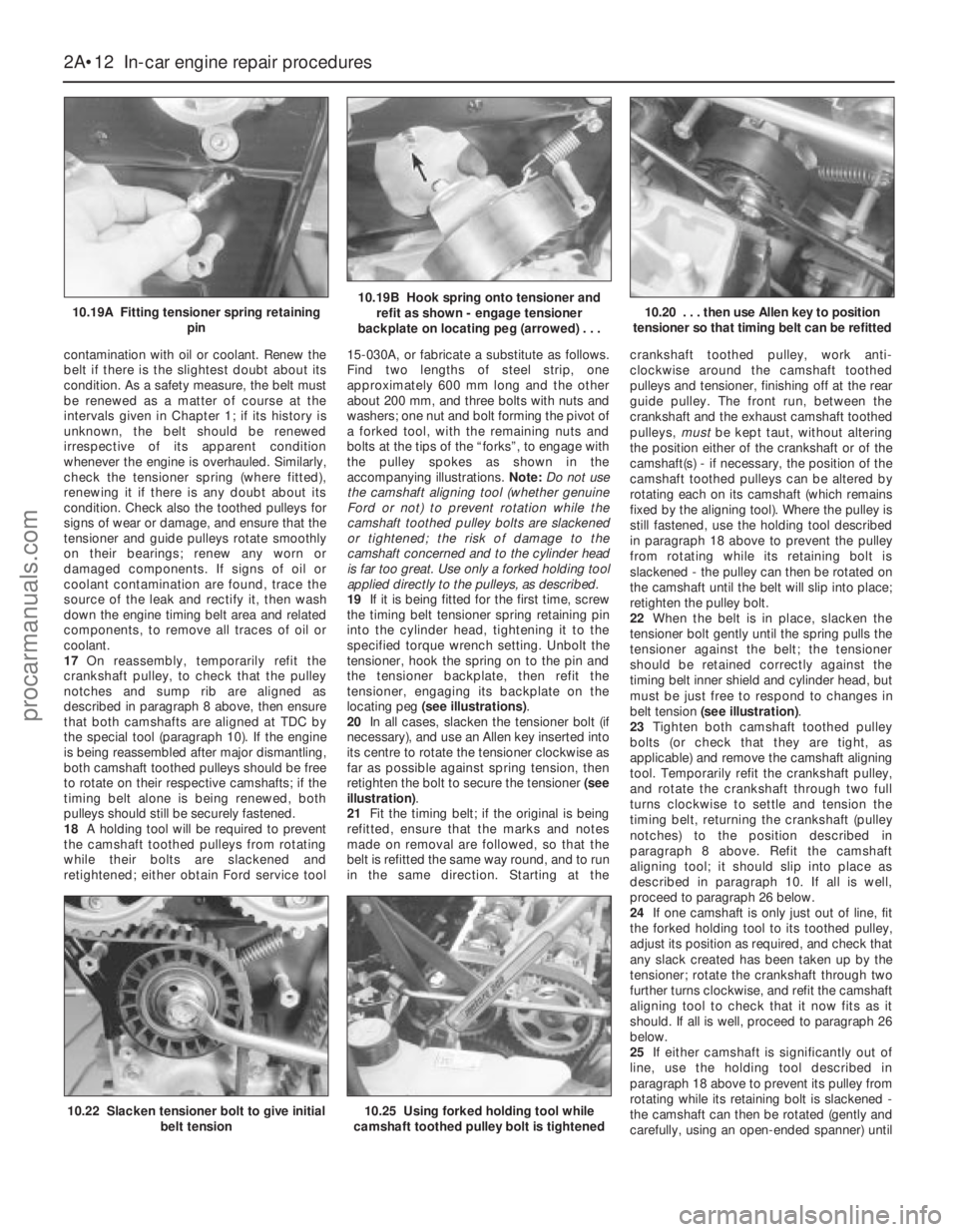
locating peg (see illustrations).
20In all cases, slacken the tensioner bolt (if
necessary), and use an Allen key inserted into
its centre to rotate the tensioner clockwise as
far as possible against spring tension, then
retighten the bolt to secure the tensioner (see
illustration).
21Fit the timing belt; if the original is being
refitted, ensure that the marks and notes
made on removal are followed, so that the
belt is refitted the same way round, and to run
in the same direction. Starting at thecrankshaft toothed pulley, work anti-
clockwise around the camshaft toothed
pulleys and tensioner, finishing off at the rear
guide pulley. The front run, between the
crankshaft and the exhaust camshaft toothed
pulleys, mustbe kept taut, without altering
the position either of the crankshaft or of the
camshaft(s) - if necessary, the position of the
camshaft toothed pulleys can be altered by
rotating each on its camshaft (which remains
fixed by the aligning tool). Where the pulley is
still fastened, use the holding tool described
in paragraph 18 above to prevent the pulley
from rotating while its retaining bolt is
slackened - the pulley can then be rotated on
the camshaft until the belt will slip into place;
retighten the pulley bolt.
22When the belt is in place, slacken the
tensioner bolt gently until the spring pulls the
tensioner against the belt; the tensioner
should be retained correctly against the
timing belt inner shield and cylinder head, but
must be just free to respond to changes in
belt tension (see illustration).
23Tighten both camshaft toothed pulley
bolts (or check that they are tight, as
applicable) and remove the camshaft aligning
tool. Temporarily refit the crankshaft pulley,
and rotate the crankshaft through two full
turns clockwise to settle and tension the
timing belt, returning the crankshaft (pulley
notches) to the position described in
paragraph 8 above. Refit the camshaft
aligning tool; it should slip into place as
described in paragraph 10. If all is well,
proceed to paragraph 26 below.
24If one camshaft is only just out of line, fit
the forked holding tool to its toothed pulley,
adjust its position as required, and check that
any slack created has been taken up by the
tensioner; rotate the crankshaft through two
further turns clockwise, and refit the camshaft
aligning tool to check that it now fits as it
should. If all is well, proceed to paragraph 26
below.
25If either camshaft is significantly out of
line, use the holding tool described in
paragraph 18 above to prevent its pulley from
rotating while its retaining bolt is slackened -
the camshaft can then be rotated (gently and
carefully, using an open-ended spanner) until
2A•12 In-car engine repair procedures
10.19A Fitting tensioner spring retaining
pin10.19B Hook spring onto tensioner and
refit as shown - engage tensioner
backplate on locating peg (arrowed) . . .10.20 . . . then use Allen key to position
tensioner so that timing belt can be refitted
10.22 Slacken tensioner bolt to give initial
belt tension10.25 Using forked holding tool while
camshaft toothed pulley bolt is tightened
procarmanuals.com
Page 67 of 279

Chapter 2 Part B: Engine removal
and general engine overhaul procedures
Compression test - description and interpretation . . . See Chapter 2A
Crankshaft - inspection . . . . . . . . . . . . . . . . . . . . . . . . . . . . . . . . . . . 13
Crankshaft - refitting and main bearing running
clearance check . . . . . . . . . . . . . . . . . . . . . . . . . . . . . . . . . . . . . . 17
Crankshaft - removal . . . . . . . . . . . . . . . . . . . . . . . . . . . . . . . . . . . . . 10
Cylinder block/crankcase - cleaning and inspection . . . . . . . . . . . . 11
Cylinder head - dismantling . . . . . . . . . . . . . . . . . . . . . . . . . . . . . . . 6
Cylinder head - reassembly . . . . . . . . . . . . . . . . . . . . . . . . . . . . . . . 8
Cylinder head and valve components - cleaning and inspection . . . 7
Engine - initial start-up after overhaul . . . . . . . . . . . . . . . . . . . . . . . . 19
Engine overhaul - dismantling sequence . . . . . . . . . . . . . . . . . . . . . 5Engine overhaul - general information . . . . . . . . . . . . . . . . . . . . . . . 2
Engine overhaul - reassembly sequence . . . . . . . . . . . . . . . . . . . . . 15
Engine/transmission - removal and refitting . . . . . . . . . . . . . . . . . . . 4
Engine/transmission removal - methods and precautions . . . . . . . . 3
General information . . . . . . . . . . . . . . . . . . . . . . . . . . . . . . . . . . . . . . 1
Main and big-end bearings - inspection . . . . . . . . . . . . . . . . . . . . . . 14
Piston/connecting rod assemblies - inspection . . . . . . . . . . . . . . . . 12
Piston/connecting rod assemblies - refitting and
big-end bearing running clearance check . . . . . . . . . . . . . . . . . . . 18
Piston/connecting rod assemblies - removal . . . . . . . . . . . . . . . . . . 9
Piston rings - refitting . . . . . . . . . . . . . . . . . . . . . . . . . . . . . . . . . . . . 16
Cylinder head
Maximum permissible gasket surface distortion . . . . . . . . . . . . . . . . . . 0.10 mm
Valve seat included angle . . . . . . . . . . . . . . . . . . . . . . . . . . . . . . . . . . . . 90°
Valve guide bore . . . . . . . . . . . . . . . . . . . . . . . . . . . . . . . . . . . . . . . . . . . 6.060 to 6.091 mm
Valves - generalInlet Exhaust
Valve lift . . . . . . . . . . . . . . . . . . . . . . . . . . . . . . . . . . . . . . . . . . . . . . . . . . 7.500 to 7.685 mm7.610 to 7.765 mm
Valve length . . . . . . . . . . . . . . . . . . . . . . . . . . . . . . . . . . . . . . . . . . . . . . . 96.870 to 97.330 mm 96.470 to 96.930 mm
Valve head diameter:
1.6 litre engine . . . . . . . . . . . . . . . . . . . . . . . . . . . . . . . . . . . . . . . . . . . 26.0 mm 24.5 mm
1.8 and 2.0 litre engines . . . . . . . . . . . . . . . . . . . . . . . . . . . . . . . . . . . 32.0 mm 28.0 mm
Valve stem diameter . . . . . . . . . . . . . . . . . . . . . . . . . . . . . . . . . . . . . . . . 6.028 to 6.043 mm 6.010 to6.025 mm
Valve stem-to-guide clearance . . . . . . . . . . . . . . . . . . . . . . . . . . . . . . . . 0.017 to 0.064 mm 0.035 to 0.081 mm
Cylinder block
Cylinder bore diameter - 1.6 litre engine:
Class 1 . . . . . . . . . . . . . . . . . . . . . . . . . . . . . . . . . . . . . . . . . . . . . . . . . 76.000 to 76.010 mm
Class 2 . . . . . . . . . . . . . . . . . . . . . . . . . . . . . . . . . . . . . . . . . . . . . . . . . 76.010 to 76.020 mm
Class 3 . . . . . . . . . . . . . . . . . . . . . . . . . . . . . . . . . . . . . . . . . . . . . . . . . 76.020 to 76.030 mm
Cylinder bore diameter - 1.8 litre engine:
Class 1 . . . . . . . . . . . . . . . . . . . . . . . . . . . . . . . . . . . . . . . . . . . . . . . . . 80.600 to 80.610 mm
Class 2 . . . . . . . . . . . . . . . . . . . . . . . . . . . . . . . . . . . . . . . . . . . . . . . . . 80.610 to 80.620 mm
Class 3 . . . . . . . . . . . . . . . . . . . . . . . . . . . . . . . . . . . . . . . . . . . . . . . . . 80.620 to 80.630 mm
Cylinder bore diameter - 2.0 litre engine:
Class 1 . . . . . . . . . . . . . . . . . . . . . . . . . . . . . . . . . . . . . . . . . . . . . . . . . 84.800 to 84.810 mm
Class 2 . . . . . . . . . . . . . . . . . . . . . . . . . . . . . . . . . . . . . . . . . . . . . . . . . 84.810 to 84.820 mm
Class 3 . . . . . . . . . . . . . . . . . . . . . . . . . . . . . . . . . . . . . . . . . . . . . . . . . 84.820 to 84.830 mm
2B•1
Easy,suitable for
novice with little
experienceFairly easy,suitable
for beginner with
some experienceFairly difficult,suitable
for competent DIY
mechanicDifficult,suitable for
experienced DIY
mechanicVery difficult,
suitable for expert DIY
or professional
Degrees of difficulty
Specifications Contents2B
procarmanuals.com