1993 FORD MONDEO headlight bulb
[x] Cancel search: headlight bulbPage 209 of 279

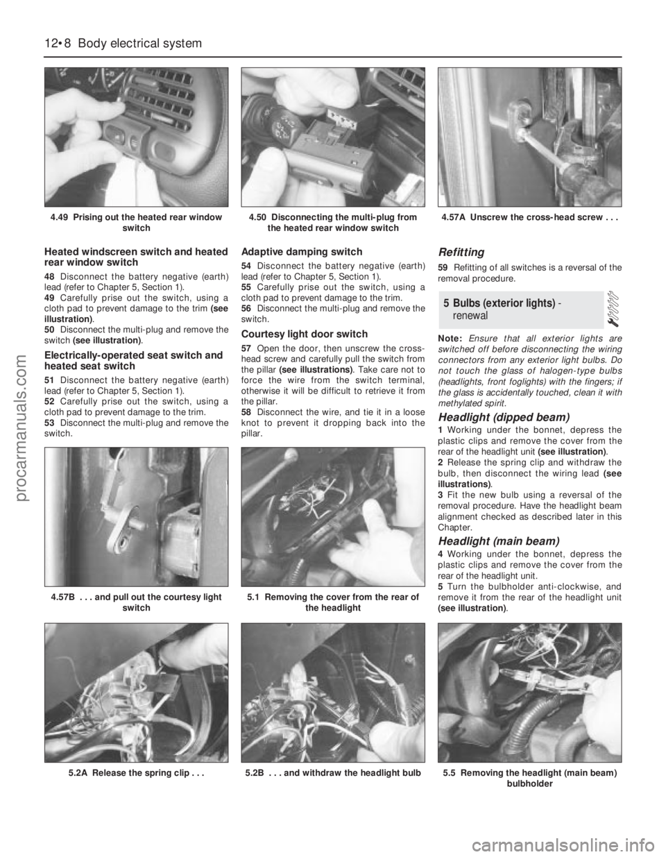
Heated windscreen switch and heated
rear window switch
48Disconnect the battery negative (earth)
lead (refer to Chapter 5, Section 1).
49Carefully prise out the switch, using a
cloth pad to prevent damage to the trim (see
illustration).
50Disconnect the multi-plug and remove the
switch (see illustration).
Electrically-operated seat switch and
heated seat switch
51Disconnect the battery negative (earth)
lead (refer to Chapter 5, Section 1).
52Carefully prise out the switch, using a
cloth pad to prevent damage to the trim.
53Disconnect the multi-plug and remove the
switch.
Adaptive damping switch
54Disconnect the battery negative (earth)
lead (refer to Chapter 5, Section 1).
55Carefully prise out the switch, using a
cloth pad to prevent damage to the trim.
56Disconnect the multi-plug and remove the
switch.
Courtesy light door switch
57Open the door, then unscrew the cross-
head screw and carefully pull the switch from
the pillar (see illustrations). Take care not to
force the wire from the switch terminal,
otherwise it will be difficult to retrieve it from
the pillar.
58Disconnect the wire, and tie it in a loose
knot to prevent it dropping back into the
pillar.
Refitting
59Refitting of all switches is a reversal of the
removal procedure.
Note:Ensure that all exterior lights are
switched off before disconnecting the wiring
connectors from any exterior light bulbs. Do
not touch the glass of halogen-type bulbs
(headlights, front foglights) with the fingers; if
the glass is accidentally touched, clean it with
methylated spirit.
Headlight (dipped beam)
1Working under the bonnet, depress the
plastic clips and remove the cover from the
rear of the headlight unit (see illustration).
2Release the spring clip and withdraw the
bulb, then disconnect the wiring lead (see
illustrations).
3Fit the new bulb using a reversal of the
removal procedure. Have the headlight beam
alignment checked as described later in this
Chapter.
Headlight (main beam)
4Working under the bonnet, depress the
plastic clips and remove the cover from the
rear of the headlight unit.
5Turn the bulbholder anti-clockwise, and
remove it from the rear of the headlight unit
(see illustration).
5 Bulbs (exterior lights) -
renewal
12•8 Body electrical system
4.49 Prising out the heated rear window
switch4.50 Disconnecting the multi-plug from
the heated rear window switch4.57A Unscrew the cross-head screw . . .
5.2A Release the spring clip . . .5.2B . . . and withdraw the headlight bulb
4.57B . . . and pull out the courtesy light
switch5.1 Removing the cover from the rear of
the headlight
5.5 Removing the headlight (main beam)
bulbholder
procarmanuals.com
Page 210 of 279

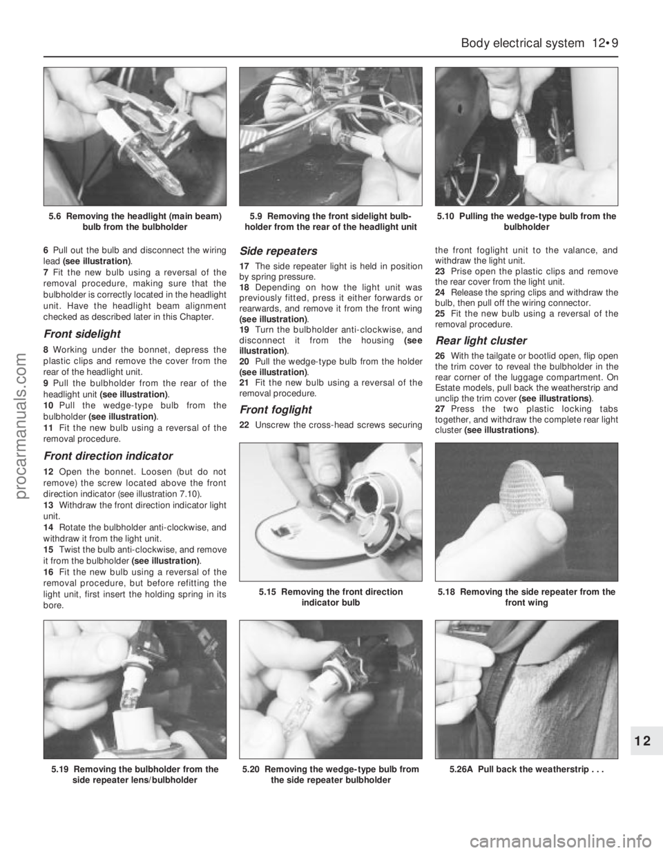
6Pull out the bulb and disconnect the wiring
lead (see illustration).
7Fit the new bulb using a reversal of the
removal procedure, making sure that the
bulbholder is correctly located in the headlight
unit. Have the headlight beam alignment
checked as described later in this Chapter.
Front sidelight
8Working under the bonnet, depress the
plastic clips and remove the cover from the
rear of the headlight unit.
9Pull the bulbholder from the rear of the
headlight unit (see illustration).
10Pull the wedge-type bulb from the
bulbholder (see illustration).
11Fit the new bulb using a reversal of the
removal procedure.
Front direction indicator
12Open the bonnet. Loosen (but do not
remove) the screw located above the front
direction indicator (see illustration 7.10).
13Withdraw the front direction indicator light
unit.
14Rotate the bulbholder anti-clockwise, and
withdraw it from the light unit.
15Twist the bulb anti-clockwise, and remove
it from the bulbholder (see illustration).
16Fit the new bulb using a reversal of the
removal procedure, but before refitting the
light unit, first insert the holding spring in its
bore.
Side repeaters
17The side repeater light is held in position
by spring pressure.
18Depending on how the light unit was
previously fitted, press it either forwards or
rearwards, and remove it from the front wing
(see illustration).
19Turn the bulbholder anti-clockwise, and
disconnect it from the housing (see
illustration).
20Pull the wedge-type bulb from the holder
(see illustration).
21Fit the new bulb using a reversal of the
removal procedure.
Front foglight
22Unscrew the cross-head screws securingthe front foglight unit to the valance, and
withdraw the light unit.
23Prise open the plastic clips and remove
the rear cover from the light unit.
24Release the spring clips and withdraw the
bulb, then pull off the wiring connector.
25Fit the new bulb using a reversal of the
removal procedure.
Rear light cluster
26With the tailgate or bootlid open, flip open
the trim cover to reveal the bulbholder in the
rear corner of the luggage compartment. On
Estate models, pull back the weatherstrip and
unclip the trim cover (see illustrations).
27Press the two plastic locking tabs
together, and withdraw the complete rear light
cluster (see illustrations).
Body electrical system 12•9
12
5.19 Removing the bulbholder from the
side repeater lens/bulbholder5.20 Removing the wedge-type bulb from
the side repeater bulbholder5.26A Pull back the weatherstrip . . .
5.15 Removing the front direction
indicator bulb5.18 Removing the side repeater from the
front wing
5.6 Removing the headlight (main beam)
bulb from the bulbholder5.9 Removing the front sidelight bulb-
holder from the rear of the headlight unit5.10 Pulling the wedge-type bulb from the
bulbholder
procarmanuals.com
Page 213 of 279

32Twist the bulbholder anti-clockwise using
a screwdriver, then remove the bulbholder
from the rear of the clock (see illustrations).
Heater control illumination
33Remove the heater control panel (Chapter
3), then twist the bulbholder anti-clockwise
and remove the bulb from the rear of the
panel.
Removal
1Disconnect the battery negative (earth) lead
(refer to Chapter 5, Section 1).
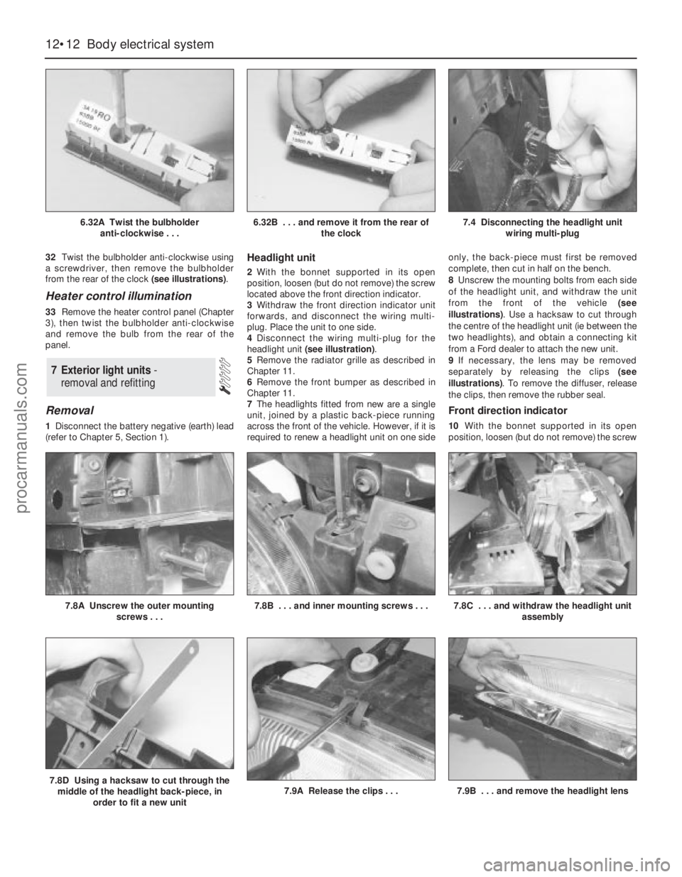
Headlight unit
2With the bonnet supported in its open
position, loosen (but do not remove) the screw
located above the front direction indicator.
3Withdraw the front direction indicator unit
forwards, and disconnect the wiring multi-
plug. Place the unit to one side.
4Disconnect the wiring multi-plug for the
headlight unit (see illustration).
5Remove the radiator grille as described in
Chapter 11.
6Remove the front bumper as described in
Chapter 11.
7The headlights fitted from new are a single
unit, joined by a plastic back-piece running
across the front of the vehicle. However, if it is
required to renew a headlight unit on one sideonly, the back-piece must first be removed
complete, then cut in half on the bench.
8Unscrew the mounting bolts from each side
of the headlight unit, and withdraw the unit
from the front of the vehicle (see
illustrations). Use a hacksaw to cut through
the centre of the headlight unit (ie between the
two headlights), and obtain a connecting kit
from a Ford dealer to attach the new unit.
9If necessary, the lens may be removed
separately by releasing the clips (see
illustrations). To remove the diffuser, release
the clips, then remove the rubber seal.
Front direction indicator
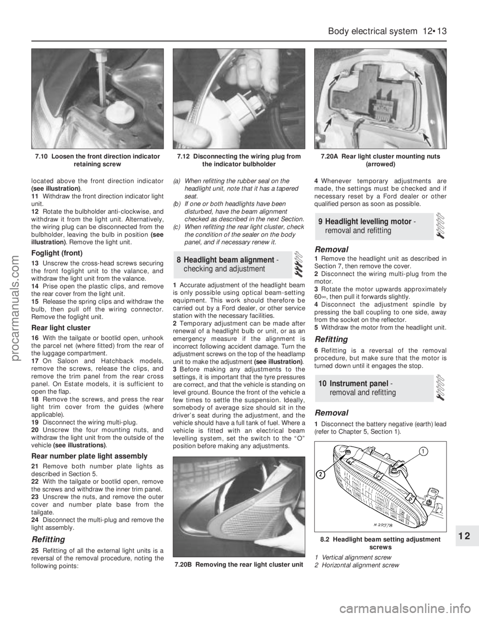
10With the bonnet supported in its open
position, loosen (but do not remove) the screw
7 Exterior light units -
removal and refitting
12•12 Body electrical system
6.32A Twist the bulbholder
anti-clockwise . . .6.32B . . . and remove it from the rear of
the clock7.4 Disconnecting the headlight unit
wiring multi-plug
7.8D Using a hacksaw to cut through the
middle of the headlight back-piece, in
order to fit a new unit7.9A Release the clips . . .7.9B . . . and remove the headlight lens
7.8A Unscrew the outer mounting
screws . . .7.8B . . . and inner mounting screws . . .7.8C . . . and withdraw the headlight unit
assembly
procarmanuals.com
Page 214 of 279

located above the front direction indicator
(see illustration).
11Withdraw the front direction indicator light
unit.
12Rotate the bulbholder anti-clockwise, and
withdraw it from the light unit. Alternatively,
the wiring plug can be disconnected from the
bulbholder, leaving the bulb in position (see
illustration). Remove the light unit.
Foglight (front)
13Unscrew the cross-head screws securing
the front foglight unit to the valance, and
withdraw the light unit from the valance.
14Prise open the plastic clips, and remove
the rear cover from the light unit.
15Release the spring clips and withdraw the
bulb, then pull off the wiring connector.
Remove the foglight unit.
Rear light cluster
16With the tailgate or bootlid open, unhook
the parcel net (where fitted) from the rear of
the luggage compartment.
17On Saloon and Hatchback models,
remove the screws, release the clips, and
remove the trim panel from the rear cross
panel. On Estate models, it is sufficient to
open the flap.
18Remove the screws, and press the rear
light trim cover from the guides (where
applicable).
19Disconnect the wiring multi-plug.
20Unscrew the four mounting nuts, and
withdraw the light unit from the outside of the
vehicle (see illustrations).
Rear number plate light assembly
21Remove both number plate lights as
described in Section 5.
22With the tailgate or bootlid open, remove
the screws and withdraw the inner trim panel.
23Unscrew the nuts, and remove the outer
cover and number plate base from the
tailgate.
24Disconnect the multi-plug and remove the
light assembly.
Refitting
25Refitting of all the external light units is a
reversal of the removal procedure, noting the
following points:(a) When refitting the rubber seal on the
headlight unit, note that it has a tapered
seat.
(b) If one or both headlights have been
disturbed, have the beam alignment
checked as described in the next Section.
(c) When refitting the rear light cluster, check
the condition of the sealer on the body
panel, and if necessary renew it.
1Accurate adjustment of the headlight beam
is only possible using optical beam-setting
equipment. This work should therefore be
carried out by a Ford dealer, or other service
station with the necessary facilities.
2Temporary adjustment can be made after
renewal of a headlight bulb or unit, or as an
emergency measure if the alignment is
incorrect following accident damage. Turn the
adjustment screws on the top of the headlamp
unit to make the adjustment (see illustration).
3Before making any adjustments to the
settings, it is important that the tyre pressures
are correct, and that the vehicle is standing on
level ground. Bounce the front of the vehicle a
few times to settle the suspension. Ideally,
somebody of average size should sit in the
driver’s seat during the adjustment, and the
vehicle should have a full tank of fuel. Where a
vehicle is fitted with an electrical beam
levelling system, set the switch to the “O”
position before making any adjustments.4Whenever temporary adjustments are
made, the settings must be checked and if
necessary reset by a Ford dealer or other
qualified person as soon as possible.
Removal
1Remove the headlight unit as described in
Section 7, then remove the cover.
2Disconnect the wiring multi-plug from the
motor.
3Rotate the motor upwards approximately
60°, then pull it forwards slightly.
4Disconnect the adjustment spindle by
pressing the ball coupling to one side, away
from the socket on the reflector.
5Withdraw the motor from the headlight unit.
Refitting
6Refitting is a reversal of the removal
procedure, but make sure that the motor is
turned down until it engages the stop.
Removal
1Disconnect the battery negative (earth) lead
(refer to Chapter 5, Section 1).
10 Instrument panel -
removal and refitting
9 Headlight levelling motor -
removal and refitting
8 Headlight beam alignment-
checking and adjustment
Body electrical system 12•13
12
7.20B Removing the rear light cluster unit
8.2 Headlight beam setting adjustment
screws
1 Vertical alignment screw
2 Horizontal alignment screw
7.10 Loosen the front direction indicator
retaining screw7.12 Disconnecting the wiring plug from
the indicator bulbholder7.20A Rear light cluster mounting nuts
(arrowed)
procarmanuals.com