1993 FORD MONDEO engine
[x] Cancel search: enginePage 176 of 279
3Start the engine, and allow it to run at a fast
idle. Check the hoses and connections for
leaks.
4Stop the engine, and recheck the fluid level.
Add more if necessary, up to the “MAX” or
“MAX COLD” mark.
5Start the engine again, allow it to idle, then
bleed the system by slowly turning the
steering wheel from side to side several times.
This should purge the system of all internal
air. However, if air remains in the system
(indicated by the steering operation being very
noisy), leave the vehicle overnight, and repeat
the procedure again the next day.
6If air still remains in the system, it may be
necessary to resort to the Ford method of
bleeding, which uses a vacuum pump. Turn
the steering to the right until it is near the stop,
then fit the vacuum pump to the fluid
reservoir, and apply 0.15 bars of vacuum.
Maintain the vacuum for a minimum of
5 minutes, then repeat the procedure with the
steering turned to the left.
7Keep the fluid level topped-up throughout
the bleeding procedure; note that, as the fluid
temperature increases, the level will rise.
8On completion, switch off the engine, and
return the front wheels to the straight-ahead
position.
Removal
1Disconnect the battery negative (earth) lead
(refer to Chapter 5, Section 1).
2Unscrew and remove the bolt securing the
hydraulic fluid line support to the engine lifting
bracket on the right-hand side of the engine.
3Unscrew and remove the bolt securing the
hydraulic fluid line support to the pump
mounting bracket.
4Position a suitable container beneath the
power steering pump, to catch spilt fluid.
5Loosen the clip, and disconnect the fluid
supply hose from the pump inlet. Plug the
hose, to prevent the ingress of dust and dirt.
6Unscrew the union nut, and disconnect the
high-pressure line from the pump. Allow the
fluid to drain into the container.
7Apply the handbrake, then jack up the front
of the vehicle and support it on axle stands.
Remove the right-hand front wheel.
8Unbolt and remove the lower drivebelt
cover.
9Using a spanner, rotate the drivebelt
tensioner in a clockwise direction to release
the belt tension, then slip the drivebelt off the
pulleys and remove from the vehicle. Refer to
Chapter 1 if necessary.
10Unscrew and remove the four mounting
bolts, and withdraw the power steering pump
from its bracket. Access to the bolts on the
right-hand side of the engine is gained by
turning the pump pulley until a hole lines up
with the bolt.
Refitting
11Locate the power steering pump on the
mounting bracket, and secure with the four
bolts. Tighten the bolts to the specified
torque.
12Slip the drivebelt over the pulleys, then
rotate the drivebelt tensioner in a clockwise
direction, and locate the drivebelt on it.
Release the tensioner to tension the drivebelt.
13Refit the lower belt cover.
14Refit the right-hand front wheel, and lower
the vehicle to the ground.
15If necessary, the sealing ring on the high-
pressure outlet should be renewed, using the
same procedure as described in Section 30,
paragraph 8.
16Reconnect the high-pressure line to the
pump, and tighten the union nut.
17Reconnect the fluid supply hose to the
pump inlet, and tighten the clip.
18Refit the hydraulic fluid line support to the
pump mounting bracket, and tighten the bolt.
19Refit the hydraulic fluid line support to the
engine lifting bracket on the right-hand side of
the engine, and tighten the bolt.
20Reconnect the battery negative lead.
21Bleed the power steering hydraulic
system as described in Section 33.
1Apply the handbrake, then jack up the front
of the vehicle and support it on axle stands.
Remove the appropriate front roadwheel.
2Using a suitable spanner, slacken the
locknut on the track rod by a quarter-turn.
Hold the track rod end stationary with another
spanner engaged with the special flats while
loosening the locknut.
3Extract the split pin, then unscrew and
remove the track rod end balljoint retaining
nut.
4To release the tapered shank of the balljoint
from the steering knuckle arm, use a balljoint
separator tool (if the balljoint is to be re-used,
take care not to damage the dust cover when
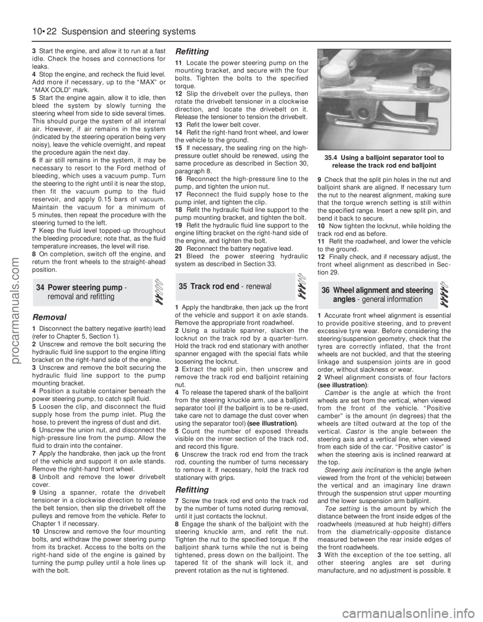
using the separator tool) (see illustration).
5Count the number of exposed threads
visible on the inner section of the track rod,
and record this figure.
6Unscrew the track rod end from the track
rod, counting the number of turns necessary
to remove it. If necessary, hold the track rod
stationary with grips.
Refitting
7Screw the track rod end onto the track rod
by the number of turns noted during removal,
until it just contacts the locknut.
8Engage the shank of the balljoint with the
steering knuckle arm, and refit the nut.
Tighten the nut to the specified torque. If the
balljoint shank turns while the nut is being
tightened, press down on the balljoint. The
tapered fit of the shank will lock it, and
prevent rotation as the nut is tightened.9Check that the split pin holes in the nut and
balljoint shank are aligned. If necessary turn
the nut to the nearest alignment, making sure
that the torque wrench setting is still within
the specified range. Insert a new split pin, and
bend it back to secure.
10Now tighten the locknut, while holding the
track rod end as before.
11Refit the roadwheel, and lower the vehicle
to the ground.
12Finally check, and if necessary adjust, the
front wheel alignment as described in Sec-
tion 29.
1Accurate front wheel alignment is essential
to provide positive steering, and to prevent
excessive tyre wear. Before considering the
steering/suspension geometry, check that the
tyres are correctly inflated, that the front
wheels are not buckled, and that the steering
linkage and suspension joints are in good
order, without slackness or wear.
2Wheel alignment consists of four factors
(see illustration):
Camberis the angle at which the front
wheels are set from the vertical, when viewed
from the front of the vehicle. “Positive
camber” is the amount (in degrees) that the
wheels are tilted outward at the top of the
vertical. Castoris the angle between the
steering axis and a vertical line, when viewed
from each side of the car. “Positive castor” is
when the steering axis is inclined rearward at
the top.
Steering axis inclinationis the angle (when
viewed from the front of the vehicle) between
the vertical and an imaginary line drawn
through the suspension strut upper mounting
and the lower suspension arm balljoint.
Toe settingis the amount by which the
distance between the front inside edges of the
roadwheels (measured at hub height) differs
from the diametrically-opposite distance
measured between the rear inside edges of
the front roadwheels.
3With the exception of the toe setting, all
other steering angles are set during
manufacture, and no adjustment is possible. It
36 Wheel alignment and steering
angles - general information35 Track rod end - renewal34 Power steering pump -
removal and refitting
10•22 Suspension and steering systems
35.4 Using a balljoint separator tool to
release the track rod end balljoint
procarmanuals.com
Page 178 of 279
Chapter 11 Bodywork and fittings
Body side-trim mouldings and adhesive emblems - removal
and refitting . . . . . . . . . . . . . . . . . . . . . . . . . . . . . . . . . . . . . . . . . . 25
Bonnet - removal, refitting and adjustment . . . . . . . . . . . . . . . . . . . . 8
Bonnet lock - removal, refitting and adjustment . . . . . . . . . . . . . . . . 10
Bonnet release cable and lever - removal and refitting . . . . . . . . . . . 9
Boot lid - removal and refitting . . . . . . . . . . . . . . . . . . . . . . . . . . . . . 18
Boot lid lock components - removal and refitting . . . . . . . . . . . . . . . 19
Bumpers - removal and refitting . . . . . . . . . . . . . . . . . . . . . . . . . . . . 6
Central locking system components - testing, removal and refitting . 23
Centre console - removal and refitting . . . . . . . . . . . . . . . . . . . . . . . 30
Door - removal and refitting . . . . . . . . . . . . . . . . . . . . . . . . . . . . . . . 15
Door handle and lock components - removal and refitting . . . . . . . . 14
Door inner trim panel - removal and refitting . . . . . . . . . . . . . . . . . . 11
Door window glass - removal and refitting . . . . . . . . . . . . . . . . . . . . 12
Door window regulator - removal and refitting . . . . . . . . . . . . . . . . . 13
Exterior mirror and glass - removal and refitting . . . . . . . . . . . . . . . . 16
Facia - removal and refitting . . . . . . . . . . . . . . . . . . . . . . . . . . . . . . . 33
General information . . . . . . . . . . . . . . . . . . . . . . . . . . . . . . . . . . . . . . 1Glovebox - removal and refitting . . . . . . . . . . . . . . . . . . . . . . . . . . . . 32
Interior mirror - removal and refitting . . . . . . . . . . . . . . . . . . . . . . . . 17
Interior trim panels - removal and refitting . . . . . . . . . . . . . . . . . . . . 29
Maintenance - bodywork and underframe . . . . . . . . . . . . . . . . . . . . 2
Maintenance - upholstery and carpets . . . . . . . . . . . . . . . . . . . . . . . 3
Major body damage - repair . . . . . . . . . . . . . . . . . . . . . . . . . . . . . . . 5
Minor body damage - repair . . . . . . . . . . . . . . . . . . . . . . . . . . . . . . . 4
Overhead console - removal and refitting . . . . . . . . . . . . . . . . . . . . . 31
Radiator grille - removal and refitting . . . . . . . . . . . . . . . . . . . . . . . . 7
Seat belts - removal and refitting . . . . . . . . . . . . . . . . . . . . . . . . . . . 28
Seats - removal and refitting . . . . . . . . . . . . . . . . . . . . . . . . . . . . . . . 27
Sunroof - general information and adjustment . . . . . . . . . . . . . . . . . 26
Tailgate - removal and refitting . . . . . . . . . . . . . . . . . . . . . . . . . . . . . 20
Tailgate lock components - removal and refitting . . . . . . . . . . . . . . . 22
Tailgate support strut - removal and refitting . . . . . . . . . . . . . . . . . . 21
Wheel arch liner - removal and refitting . . . . . . . . . . . . . . . . . . . . . . 34
Windscreen and fixed windows - removal and refitting . . . . . . . . . . 24
Torque wrench settingsNm lbf ft
Bonnet and tailgate hinges . . . . . . . . . . . . . . . . . . . . . . . . . . . . . . . . . . . 24 18
Boot lid . . . . . . . . . . . . . . . . . . . . . . . . . . . . . . . . . . . . . . . . . . . . . . . . . . 10 7
Front seat mounting bolts . . . . . . . . . . . . . . . . . . . . . . . . . . . . . . . . . . . . 38 28
Seat belt mounting nuts and bolts . . . . . . . . . . . . . . . . . . . . . . . . . . . . . 38 28
Bumper mounting nuts . . . . . . . . . . . . . . . . . . . . . . . . . . . . . . . . . . . . . . 10 7
11•1
Easy,suitable for
novice with little
experienceFairly easy,suitable
for beginner with
some experienceFairly difficult,suitable
for competent DIY
mechanicDifficult,suitable for
experienced DIY
mechanicVery difficult,
suitable for expert DIY
or professional
Degrees of difficulty
Specifications Contents
11
The bodyshell and underframe on all
models is of all-steel welded construction,
incorporating progressive crumple zones at
the front and rear, and a rigid centre safety
cell. The bulkhead behind the engine
compartment incorporates crash grooves
which determine its energy-absorption
characteristics, and special beams to prevent
the intrusion of the front wheels into the
passenger compartment during a serious
accident. All passenger doors incorporate
side impact bars.
All sheet metal surfaces which are prone tocorrosion are galvanized. The painting
process includes a base colour which closely
matches the final topcoat, so that any stone
damage is not noticeable.
Hatchback, Saloon and Estate versions are
available. The front section of the vehicle up to
the “B” pillar is identical on all models.
Automatic seat belts are fitted to all models,
and the front seat belt stalks are mounted on
automatic tensioners (also known as
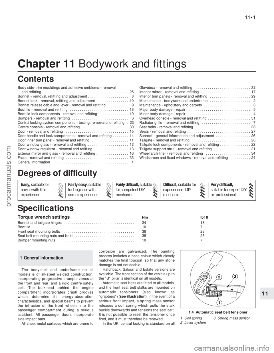
“grabbers”) (see illustration). In the event of a
serious front impact, a spring mass sensor
releases a coil spring which pulls the stalk
buckle downwards and tensions the seat belt.
It is not possible to reset the tensioner once
fired, and it must therefore be renewed.
In the UK, central locking is standard on all
1 General information
1.4 Automatic seat belt tensioner
1 Coil spring 3 Spring mass sensor
2 Lever system
procarmanuals.com
Page 179 of 279
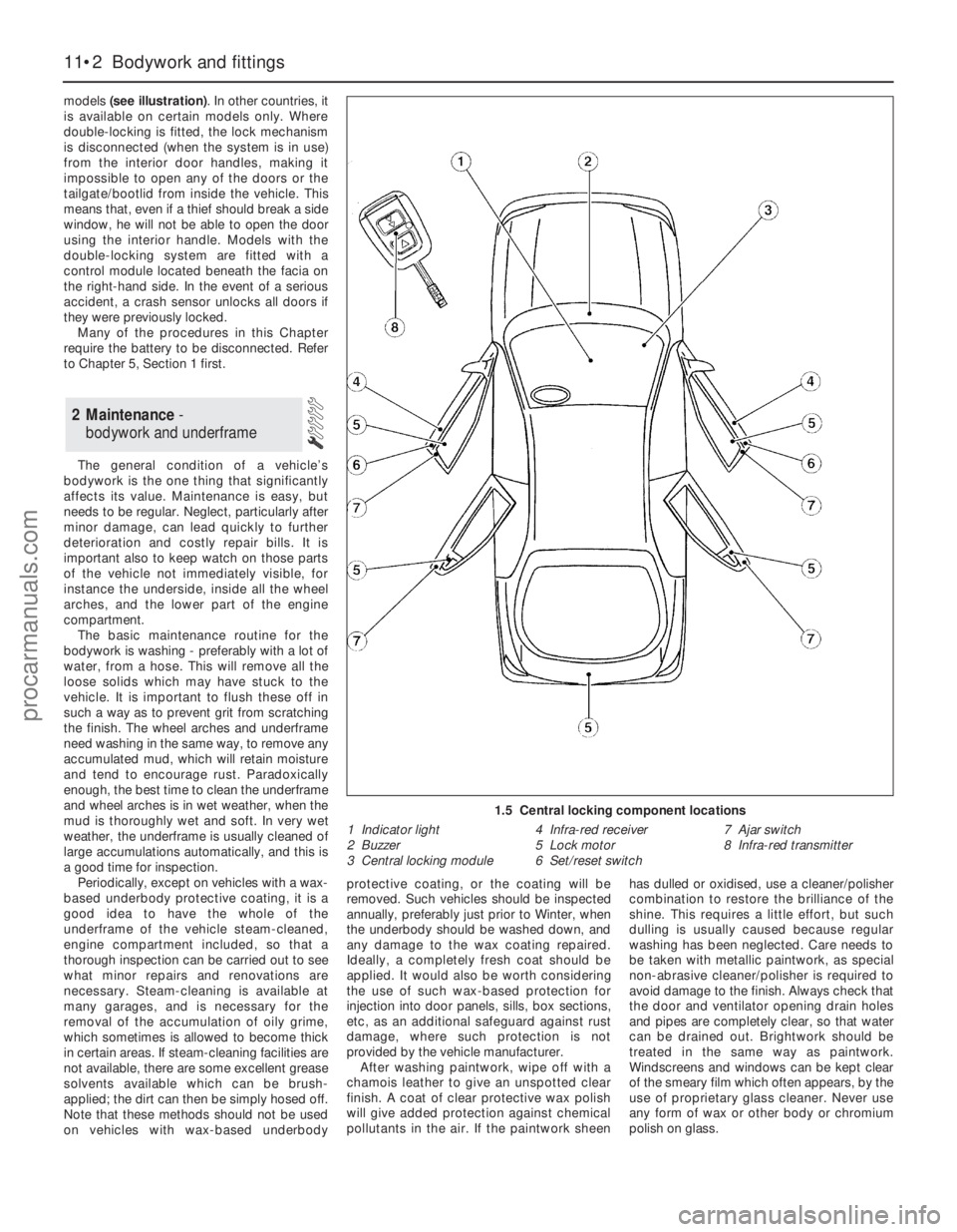
models (see illustration). In other countries, it
is available on certain models only. Where
double-locking is fitted, the lock mechanism
is disconnected (when the system is in use)
from the interior door handles, making it
impossible to open any of the doors or the
tailgate/bootlid from inside the vehicle. This
means that, even if a thief should break a side
window, he will not be able to open the door
using the interior handle. Models with the
double-locking system are fitted with a
control module located beneath the facia on
the right-hand side. In the event of a serious
accident, a crash sensor unlocks all doors if
they were previously locked.
Many of the procedures in this Chapter
require the battery to be disconnected. Refer
to Chapter 5, Section 1 first.
The general condition of a vehicle’s
bodywork is the one thing that significantly
affects its value. Maintenance is easy, but
needs to be regular. Neglect, particularly after
minor damage, can lead quickly to further
deterioration and costly repair bills. It is
important also to keep watch on those parts
of the vehicle not immediately visible, for
instance the underside, inside all the wheel
arches, and the lower part of the engine
compartment.
The basic maintenance routine for the
bodywork is washing - preferably with a lot of
water, from a hose. This will remove all the
loose solids which may have stuck to the
vehicle. It is important to flush these off in
such a way as to prevent grit from scratching
the finish. The wheel arches and underframe
need washing in the same way, to remove any
accumulated mud, which will retain moisture
and tend to encourage rust. Paradoxically
enough, the best time to clean the underframe
and wheel arches is in wet weather, when the
mud is thoroughly wet and soft. In very wet
weather, the underframe is usually cleaned of
large accumulations automatically, and this is
a good time for inspection.
Periodically, except on vehicles with a wax-
based underbody protective coating, it is a
good idea to have the whole of the
underframe of the vehicle steam-cleaned,
engine compartment included, so that a
thorough inspection can be carried out to see
what minor repairs and renovations are
necessary. Steam-cleaning is available at
many garages, and is necessary for the
removal of the accumulation of oily grime,
which sometimes is allowed to become thick
in certain areas. If steam-cleaning facilities are
not available, there are some excellent grease
solvents available which can be brush-
applied; the dirt can then be simply hosed off.
Note that these methods should not be used
on vehicles with wax-based underbodyprotective coating, or the coating will be
removed. Such vehicles should be inspected
annually, preferably just prior to Winter, when
the underbody should be washed down, and
any damage to the wax coating repaired.
Ideally, a completely fresh coat should be
applied. It would also be worth considering
the use of such wax-based protection for
injection into door panels, sills, box sections,
etc, as an additional safeguard against rust
damage, where such protection is not
provided by the vehicle manufacturer.
After washing paintwork, wipe off with a
chamois leather to give an unspotted clear
finish. A coat of clear protective wax polish
will give added protection against chemical
pollutants in the air. If the paintwork sheenhas dulled or oxidised, use a cleaner/polisher
combination to restore the brilliance of the
shine. This requires a little effort, but such
dulling is usually caused because regular
washing has been neglected. Care needs to
be taken with metallic paintwork, as special
non-abrasive cleaner/polisher is required to
avoid damage to the finish. Always check that
the door and ventilator opening drain holes
and pipes are completely clear, so that water
can be drained out. Brightwork should be
treated in the same way as paintwork.
Windscreens and windows can be kept clear
of the smeary film which often appears, by the
use of proprietary glass cleaner. Never use
any form of wax or other body or chromium
polish on glass.
2 Maintenance -
bodywork and underframe
11•2 Bodywork and fittings
1.5 Central locking component locations
1 Indicator light
2 Buzzer
3 Central locking module4 Infra-red receiver
5 Lock motor
6 Set/reset switch7 Ajar switch
8 Infra-red transmitter
procarmanuals.com
Page 182 of 279
7Disconnect the rear exhaust mounting
rubber, and support the exhaust system on an
axle stand.
8Remove the screws securing the wheel
arch liners to the rear bumper.
9Unscrew the bumper mounting nuts, and
withdraw the bumper rearwards from the
vehicle, at the same time disconnecting the
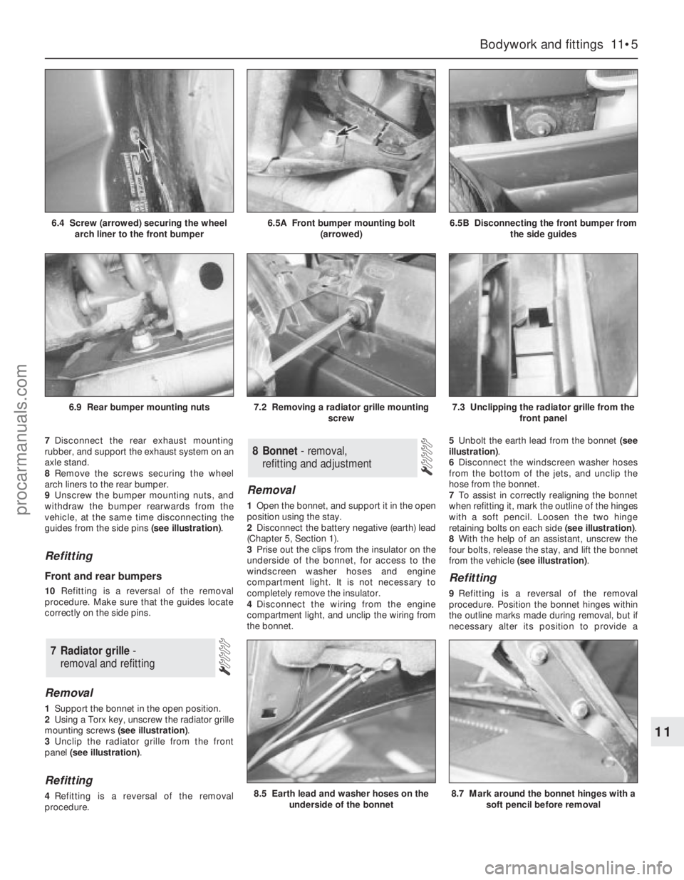
guides from the side pins (see illustration).
Refitting
Front and rear bumpers
10Refitting is a reversal of the removal
procedure. Make sure that the guides locate
correctly on the side pins.
Removal
1Support the bonnet in the open position.
2Using a Torx key, unscrew the radiator grille
mounting screws (see illustration).
3Unclip the radiator grille from the front
panel (see illustration).
Refitting
4Refitting is a reversal of the removal
procedure.
Removal
1Open the bonnet, and support it in the open
position using the stay.
2Disconnect the battery negative (earth) lead
(Chapter 5, Section 1).
3Prise out the clips from the insulator on the
underside of the bonnet, for access to the
windscreen washer hoses and engine
compartment light. It is not necessary to
completely remove the insulator.
4Disconnect the wiring from the engine
compartment light, and unclip the wiring from
the bonnet.5Unbolt the earth lead from the bonnet (see
illustration).
6Disconnect the windscreen washer hoses
from the bottom of the jets, and unclip the
hose from the bonnet.
7To assist in correctly realigning the bonnet
when refitting it, mark the outline of the hinges
with a soft pencil. Loosen the two hinge
retaining bolts on each side (see illustration).
8With the help of an assistant, unscrew the
four bolts, release the stay, and lift the bonnet
from the vehicle (see illustration).
Refitting
9Refitting is a reversal of the removal
procedure. Position the bonnet hinges within
the outline marks made during removal, but if
necessary alter its position to provide a
8 Bonnet - removal,
refitting and adjustment
7 Radiator grille-
removal and refitting
Bodywork and fittings 11•5
11
7.3 Unclipping the radiator grille from the
front panel
8.5 Earth lead and washer hoses on the
underside of the bonnet
6.9 Rear bumper mounting nuts7.2 Removing a radiator grille mounting
screw
8.7 Mark around the bonnet hinges with a
soft pencil before removal
6.4 Screw (arrowed) securing the wheel
arch liner to the front bumper6.5A Front bumper mounting bolt
(arrowed)6.5B Disconnecting the front bumper from
the side guides
procarmanuals.com
Page 183 of 279
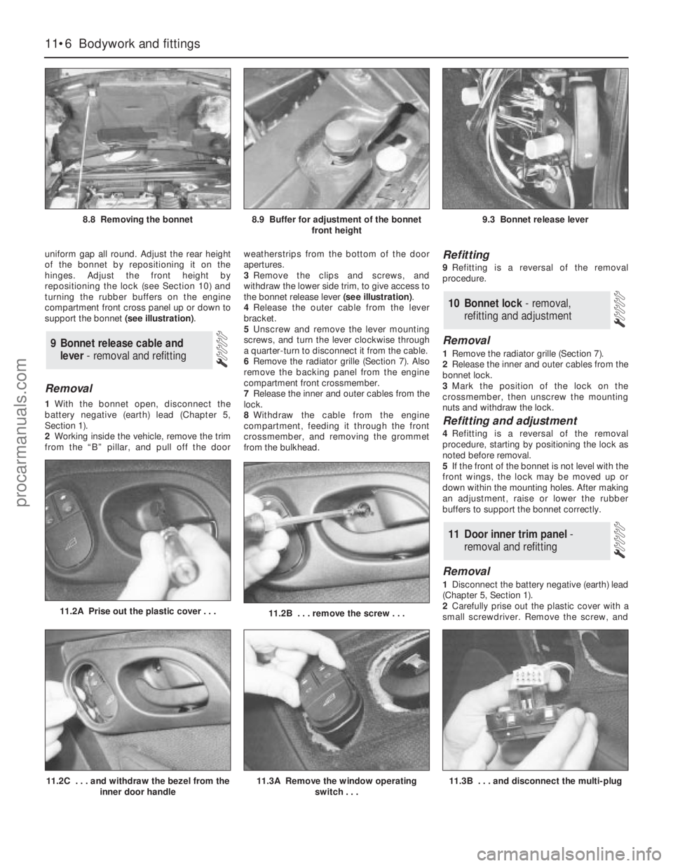
11.3B . . . and disconnect the multi-plug
uniform gap all round. Adjust the rear height
of the bonnet by repositioning it on the
hinges. Adjust the front height by
repositioning the lock (see Section 10) and
turning the rubber buffers on the engine
compartment front cross panel up or down to
support the bonnet (see illustration).
Removal
1With the bonnet open, disconnect the
battery negative (earth) lead (Chapter 5,
Section 1).
2Working inside the vehicle, remove the trim
from the “B” pillar, and pull off the doorweatherstrips from the bottom of the door
apertures.
3Remove the clips and screws, and
withdraw the lower side trim, to give access to
the bonnet release lever (see illustration).
4Release the outer cable from the lever
bracket.
5Unscrew and remove the lever mounting
screws, and turn the lever clockwise through
a quarter-turn to disconnect it from the cable.
6Remove the radiator grille (Section 7). Also
remove the backing panel from the engine
compartment front crossmember.
7Release the inner and outer cables from the
lock.
8Withdraw the cable from the engine
compartment, feeding it through the front
crossmember, and removing the grommet
from the bulkhead.
Refitting
9Refitting is a reversal of the removal
procedure.
Removal
1Remove the radiator grille (Section 7).
2Release the inner and outer cables from the
bonnet lock.
3Mark the position of the lock on the
crossmember, then unscrew the mounting
nuts and withdraw the lock.
Refitting and adjustment
4Refitting is a reversal of the removal
procedure, starting by positioning the lock as
noted before removal.
5If the front of the bonnet is not level with the
front wings, the lock may be moved up or
down within the mounting holes. After making
an adjustment, raise or lower the rubber
buffers to support the bonnet correctly.
Removal
1Disconnect the battery negative (earth) lead
(Chapter 5, Section 1).
2Carefully prise out the plastic cover with a
small screwdriver. Remove the screw, and
11 Door inner trim panel -
removal and refitting
10 Bonnet lock - removal,
refitting and adjustment
9 Bonnet release cable and
lever - removal and refitting
11•6 Bodywork and fittings
8.8 Removing the bonnet8.9 Buffer for adjustment of the bonnet
front height9.3 Bonnet release lever
11.2B . . . remove the screw . . .11.2A Prise out the plastic cover . . .
11.2C . . . and withdraw the bezel from the
inner door handle11.3A Remove the window operating
switch . . .
procarmanuals.com
Page 202 of 279
Chapter 12 Body electrical system
Air bag clock spring - removal and refitting . . . . . . . . . . . . . . . . . . . 30
Air bag control module - removal and refitting . . . . . . . . . . . . . . . . . 29
Air bag unit (driver’s side) - removal and refitting . . . . . . . . . . . . . . . 28
Anti-theft alarm system - general information . . . . . . . . . . . . . . . . . . 20
Auxiliary warning system - general information and
component renewal . . . . . . . . . . . . . . . . . . . . . . . . . . . . . . . . . . . . 19
Battery - check, maintenance and charging . . . . . . . . See Chapter 1
Battery - removal and refitting . . . . . . . . . . . . . . . . . . . See Chapter 5
Bulbs (exterior lights) - renewal . . . . . . . . . . . . . . . . . . . . . . . . . . . . . 5
Bulbs (interior lights) - renewal . . . . . . . . . . . . . . . . . . . . . . . . . . . . . 6
Clock - removal and refitting . . . . . . . . . . . . . . . . . . . . . . . . . . . . . . . 13
Compact disc player - removal and refitting . . . . . . . . . . . . . . . . . . . 25
Cruise control system - general information . . . . . . . . . . . . . . . . . . . 21
Electrical fault finding - general information . . . . . . . . . . . . . . . . . . . 2
Electrical system check . . . . . . . . . . . . . . . . . . . . . . . . See Chapter 1
Exterior light units - removal and refitting . . . . . . . . . . . . . . . . . . . . . 7
Fuses, relays and timer module - testing and renewal . . . . . . . . . . . 3
General information . . . . . . . . . . . . . . . . . . . . . . . . . . . . . . . . . . . . . . 1
Headlight beam alignment - checking and adjustment . . . . . . . . . . 8
Headlight levelling motor - removal and refitting . . . . . . . . . . . . . . . 9Horn - removal and refitting . . . . . . . . . . . . . . . . . . . . . . . . . . . . . . . 14
Instrument panel - removal and refitting . . . . . . . . . . . . . . . . . . . . . . 10
Instrument panel components - removal and refitting . . . . . . . . . . . 11
Radio aerial - removal and refitting . . . . . . . . . . . . . . . . . . . . . . . . . . 27
Radio/cassette player - coding, removal and refitting . . . . . . . . . . . 23
Radio/cassette player power amplifier - removal and refitting . . . . . 24
Speakers - removal and refitting . . . . . . . . . . . . . . . . . . . . . . . . . . . . 26
Speedometer drive cable - removal and refitting . . . . . . . . . . . . . . . 12
Stop-light switch - removal and refitting . . . . . . . . . . . See Chapter 9
Switches - removal and refitting . . . . . . . . . . . . . . . . . . . . . . . . . . . . 4
Tailgate wiper motor assembly - removal and refitting . . . . . . . . . . . 17
TCS inhibition switch - removal and refitting . . . . . . . . See Chapter 9
Trip computer module - removal and refitting . . . . . . . . . . . . . . . . . 18
Windscreen/tailgate washer system and wiper blade
check . . . . . . . . . . . . . . . . . . . . . . . . . . . . . . . . . . . . See Chapter 1
Windscreen/tailgate washer system components - removal
and refitting . . . . . . . . . . . . . . . . . . . . . . . . . . . . . . . . . . . . . . . . . . 22
Windscreen wiper motor and linkage - removal and refitting . . . . . . 16
Wiper arms - removal and refitting . . . . . . . . . . . . . . . . . . . . . . . . . . 15
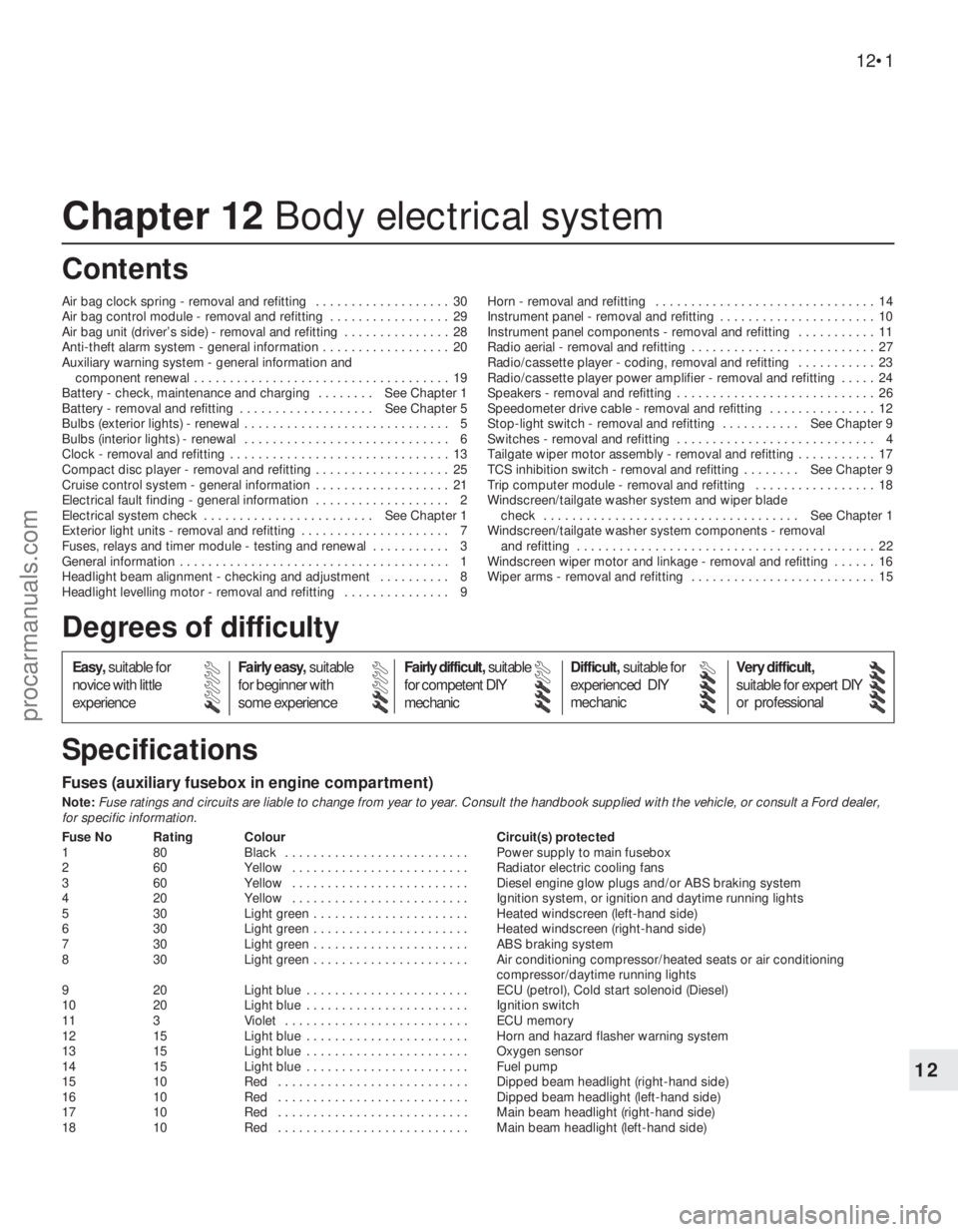
Fuses (auxiliary fusebox in engine compartment)
Note:Fuse ratings and circuits are liable to change from year to year. Consult the handbook supplied with the vehicle, or consult a Ford dealer,
for specific information.
Fuse No Rating Colour Circuit(s) protected
1 80 Black . . . . . . . . . . . . . . . . . . . . . . . . . . Power supply to main fusebox
2 60 Yellow . . . . . . . . . . . . . . . . . . . . . . . . . Radiator electric cooling fans
3 60 Yellow . . . . . . . . . . . . . . . . . . . . . . . . . Diesel engine glow plugs and/or ABS braking system
4 20 Yellow . . . . . . . . . . . . . . . . . . . . . . . . . Ignition system, or ignition and daytime running lights
5 30 Light green . . . . . . . . . . . . . . . . . . . . . . Heated windscreen (left-hand side)
6 30 Light green . . . . . . . . . . . . . . . . . . . . . . Heated windscreen (right-hand side)
7 30 Light green . . . . . . . . . . . . . . . . . . . . . . ABS braking system
8 30 Light green . . . . . . . . . . . . . . . . . . . . . . Air conditioning compressor/heated seats or air conditioning
compressor/daytime running lights
9 20 Light blue . . . . . . . . . . . . . . . . . . . . . . . ECU (petrol), Cold start solenoid (Diesel)
10 20 Light blue . . . . . . . . . . . . . . . . . . . . . . . Ignition switch
11 3 Violet . . . . . . . . . . . . . . . . . . . . . . . . . . ECU memory
12 15 Light blue . . . . . . . . . . . . . . . . . . . . . . . Horn and hazard flasher warning system
13 15 Light blue . . . . . . . . . . . . . . . . . . . . . . . Oxygen sensor
14 15 Light blue . . . . . . . . . . . . . . . . . . . . . . . Fuel pump
15 10 Red . . . . . . . . . . . . . . . . . . . . . . . . . . . Dipped beam headlight (right-hand side)
16 10 Red . . . . . . . . . . . . . . . . . . . . . . . . . . . Dipped beam headlight (left-hand side)
17 10 Red . . . . . . . . . . . . . . . . . . . . . . . . . . . Main beam headlight (right-hand side)
18 10 Red . . . . . . . . . . . . . . . . . . . . . . . . . . . Main beam headlight (left-hand side)
12•1
Easy,suitable for
novice with little
experienceFairly easy,suitable
for beginner with
some experienceFairly difficult,suitable
for competent DIY
mechanicDifficult,suitable for
experienced DIY
mechanicVery difficult,
suitable for expert DIY
or professional
Degrees of difficulty
Specifications Contents
12
procarmanuals.com
Page 203 of 279
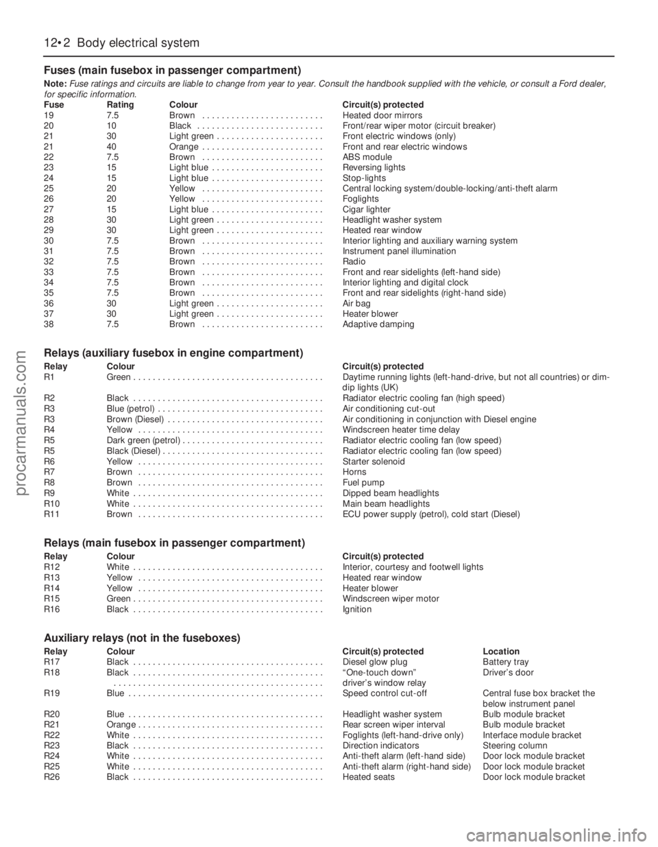
Fuses (main fusebox in passenger compartment)
Note:Fuse ratings and circuits are liable to change from year to year. Consult the handbook supplied with the vehicle, or consult a Ford dealer,
for specific information.
Fuse Rating Colour Circuit(s) protected
19 7.5 Brown . . . . . . . . . . . . . . . . . . . . . . . . . Heated door mirrors
20 10 Black . . . . . . . . . . . . . . . . . . . . . . . . . . Front/rear wiper motor (circuit breaker)
21 30 Light green . . . . . . . . . . . . . . . . . . . . . . Front electric windows (only)
21 40 Orange . . . . . . . . . . . . . . . . . . . . . . . . . Front and rear electric windows
22 7.5 Brown . . . . . . . . . . . . . . . . . . . . . . . . . ABS module
23 15 Light blue . . . . . . . . . . . . . . . . . . . . . . . Reversing lights
24 15 Light blue . . . . . . . . . . . . . . . . . . . . . . . Stop-lights
25 20 Yellow . . . . . . . . . . . . . . . . . . . . . . . . . Central locking system/double-locking/anti-theft alarm
26 20 Yellow . . . . . . . . . . . . . . . . . . . . . . . . . Foglights
27 15 Light blue . . . . . . . . . . . . . . . . . . . . . . . Cigar lighter
28 30 Light green . . . . . . . . . . . . . . . . . . . . . . Headlight washer system
29 30 Light green . . . . . . . . . . . . . . . . . . . . . . Heated rear window
30 7.5 Brown . . . . . . . . . . . . . . . . . . . . . . . . . Interior lighting and auxiliary warning system
31 7.5 Brown . . . . . . . . . . . . . . . . . . . . . . . . . Instrument panel illumination
32 7.5 Brown . . . . . . . . . . . . . . . . . . . . . . . . . Radio
33 7.5 Brown . . . . . . . . . . . . . . . . . . . . . . . . . Front and rear sidelights (left-hand side)
34 7.5 Brown . . . . . . . . . . . . . . . . . . . . . . . . . Interior lighting and digital clock
35 7.5 Brown . . . . . . . . . . . . . . . . . . . . . . . . . Front and rear sidelights (right-hand side)
36 30 Light green . . . . . . . . . . . . . . . . . . . . . . Air bag
37 30 Light green . . . . . . . . . . . . . . . . . . . . . . Heater blower
38 7.5 Brown . . . . . . . . . . . . . . . . . . . . . . . . . Adaptive damping
Relays (auxiliary fusebox in engine compartment)
Relay Colour Circuit(s) protected
R1 Green . . . . . . . . . . . . . . . . . . . . . . . . . . . . . . . . . . . . . . . Daytime running lights (left-hand-drive, but not all countries) or dim-
dip lights (UK)
R2 Black . . . . . . . . . . . . . . . . . . . . . . . . . . . . . . . . . . . . . . . Radiator electric cooling fan (high speed)
R3 Blue (petrol) . . . . . . . . . . . . . . . . . . . . . . . . . . . . . . . . . . Air conditioning cut-out
R3 Brown (Diesel) . . . . . . . . . . . . . . . . . . . . . . . . . . . . . . . . Air conditioning in conjunction with Diesel engine
R4 Yellow . . . . . . . . . . . . . . . . . . . . . . . . . . . . . . . . . . . . . . Windscreen heater time delay
R5 Dark green (petrol) . . . . . . . . . . . . . . . . . . . . . . . . . . . . . Radiator electric cooling fan (low speed)
R5 Black (Diesel) . . . . . . . . . . . . . . . . . . . . . . . . . . . . . . . . . Radiator electric cooling fan (low speed)
R6 Yellow . . . . . . . . . . . . . . . . . . . . . . . . . . . . . . . . . . . . . . Starter solenoid
R7 Brown . . . . . . . . . . . . . . . . . . . . . . . . . . . . . . . . . . . . . . Horns
R8 Brown . . . . . . . . . . . . . . . . . . . . . . . . . . . . . . . . . . . . . . Fuel pump
R9 White . . . . . . . . . . . . . . . . . . . . . . . . . . . . . . . . . . . . . . . Dipped beam headlights
R10 White . . . . . . . . . . . . . . . . . . . . . . . . . . . . . . . . . . . . . . . Main beam headlights
R11 Brown . . . . . . . . . . . . . . . . . . . . . . . . . . . . . . . . . . . . . . ECU power supply (petrol), cold start (Diesel)
Relays (main fusebox in passenger compartment)
Relay Colour Circuit(s) protected
R12 White . . . . . . . . . . . . . . . . . . . . . . . . . . . . . . . . . . . . . . . Interior, courtesy and footwell lights
R13 Yellow . . . . . . . . . . . . . . . . . . . . . . . . . . . . . . . . . . . . . . Heated rear window
R14 Yellow . . . . . . . . . . . . . . . . . . . . . . . . . . . . . . . . . . . . . . Heater blower
R15 Green . . . . . . . . . . . . . . . . . . . . . . . . . . . . . . . . . . . . . . . Windscreen wiper motor
R16 Black . . . . . . . . . . . . . . . . . . . . . . . . . . . . . . . . . . . . . . . Ignition
Auxiliary relays (not in the fuseboxes)
Relay Colour Circuit(s) protected Location
R17 Black . . . . . . . . . . . . . . . . . . . . . . . . . . . . . . . . . . . . . . . Diesel glow plug Battery tray
R18 Black . . . . . . . . . . . . . . . . . . . . . . . . . . . . . . . . . . . . . . . “One-touch down” Driver’s door
. . . . . . . . . . . . . . . . . . . . . . . . . . . . . . . . . . . . . . . . . . . driver’s window relay
R19 Blue . . . . . . . . . . . . . . . . . . . . . . . . . . . . . . . . . . . . . . . . Speed control cut-off Central fuse box bracket the
below instrument panel
R20 Blue . . . . . . . . . . . . . . . . . . . . . . . . . . . . . . . . . . . . . . . . Headlight washer system Bulb module bracket
R21 Orange . . . . . . . . . . . . . . . . . . . . . . . . . . . . . . . . . . . . . . Rear screen wiper interval Bulb module bracket
R22 White . . . . . . . . . . . . . . . . . . . . . . . . . . . . . . . . . . . . . . . Foglights (left-hand-drive only) Interface module bracket
R23 Black . . . . . . . . . . . . . . . . . . . . . . . . . . . . . . . . . . . . . . . Direction indicators Steering column
R24 White . . . . . . . . . . . . . . . . . . . . . . . . . . . . . . . . . . . . . . . Anti-theft alarm (left-hand side) Door lock module bracket
R25 White . . . . . . . . . . . . . . . . . . . . . . . . . . . . . . . . . . . . . . . Anti-theft alarm (right-hand side) Door lock module bracket
R26 Black . . . . . . . . . . . . . . . . . . . . . . . . . . . . . . . . . . . . . . . Heated seats Door lock module bracket
12•2 Body electrical system
procarmanuals.com
Page 204 of 279
BulbsWattage Type
Headlight main beam . . . . . . . . . . . . . . . . . . . . . . . . . . . . . . . . . . . . . . . 55 Halogen
Headlight dipped beam . . . . . . . . . . . . . . . . . . . . . . . . . . . . . . . . . . . . . . 55 Halogen
Foglights . . . . . . . . . . . . . . . . . . . . . . . . . . . . . . . . . . . . . . . . . . . . . . . . . 55 Halogen
Sidelights . . . . . . . . . . . . . . . . . . . . . . . . . . . . . . . . . . . . . . . . . . . . . . . . . 5 Wedge
Direction indicator lights . . . . . . . . . . . . . . . . . . . . . . . . . . . . . . . . . . . . . 21 Bayonet
Side repeater lights . . . . . . . . . . . . . . . . . . . . . . . . . . . . . . . . . . . . . . . . . 5 Wedge
Stop-lights . . . . . . . . . . . . . . . . . . . . . . . . . . . . . . . . . . . . . . . . . . . . . . . . 21 Bayonet
Reversing lights . . . . . . . . . . . . . . . . . . . . . . . . . . . . . . . . . . . . . . . . . . . . 21 Bayonet
Rear fog/tail lights (Saloon and Estate) . . . . . . . . . . . . . . . . . . . . . . . . . . 21/4 Bayonet
Rear tail light (Saloon and Hatchback) . . . . . . . . . . . . . . . . . . . . . . . . . . 5 Bayonet
Number plate lights . . . . . . . . . . . . . . . . . . . . . . . . . . . . . . . . . . . . . . . . . 5 Festoon
Engine compartment . . . . . . . . . . . . . . . . . . . . . . . . . . . . . . . . . . . . . . . . 10 Wedge
Interior lights . . . . . . . . . . . . . . . . . . . . . . . . . . . . . . . . . . . . . . . . . . . . . . 10 Festoon
Reading light . . . . . . . . . . . . . . . . . . . . . . . . . . . . . . . . . . . . . . . . . . . . . . 5 Wedge
Torque wrench settingsNm lbf ft
Windscreen wiper motor bolts:
Into old motor (see text) . . . . . . . . . . . . . . . . . . . . . . . . . . . . . . . . . . . 8 6
Into new motor (see text) . . . . . . . . . . . . . . . . . . . . . . . . . . . . . . . . . . . 12 9
Body electrical system 12•3
12
Warning: Before carrying out any
work on the electrical system,
read through the precautions
given in “Safety first!” at the beginning of
this manual.The electrical system is of 12-volt negative
earth type. Power for the lights and all
electrical accessories is supplied by a
lead/acid battery which is charged by the
alternator.
This Chapter covers repair and service
procedures for the various electrical
components not associated with the engine.
Information on the battery, ignition system,alternator, and starter motor can be found in
Chapter 5.
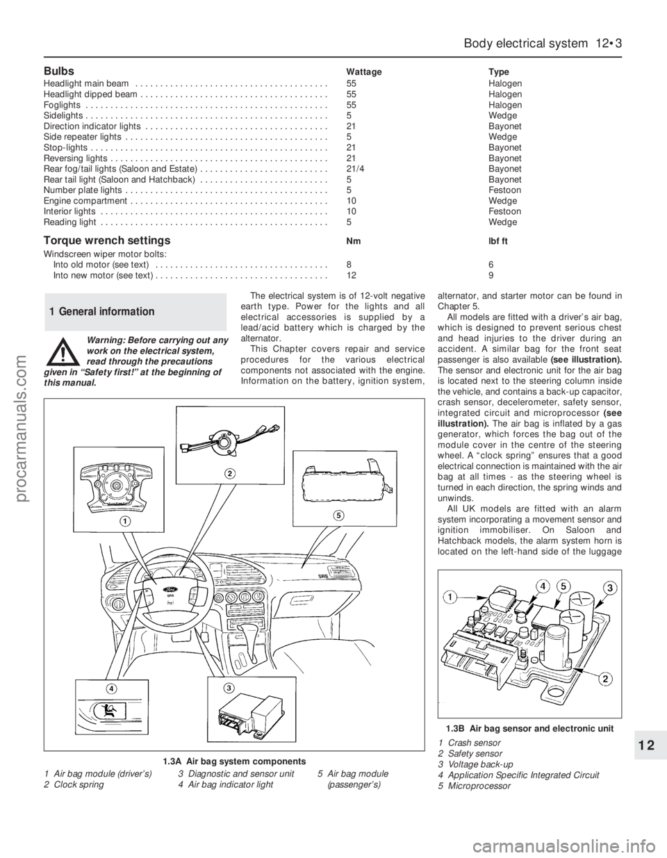
All models are fitted with a driver’s air bag,
which is designed to prevent serious chest
and head injuries to the driver during an
accident. A similar bag for the front seat
passenger is also available (see illustration).
The sensor and electronic unit for the air bag
is located next to the steering column inside
the vehicle, and contains a back-up capacitor,
crash sensor, decelerometer, safety sensor,
integrated circuit and microprocessor (see
illustration). The air bag is inflated by a gas
generator, which forces the bag out of the
module cover in the centre of the steering
wheel. A “clock spring” ensures that a good
electrical connection is maintained with the air
bag at all times - as the steering wheel is
turned in each direction, the spring winds and
unwinds.
All UK models are fitted with an alarm
system incorporating a movement sensor and
ignition immobiliser. On Saloon and
Hatchback models, the alarm system horn is
located on the left-hand side of the luggage
1 General information
1.3A Air bag system components
1 Air bag module (driver’s)
2 Clock spring3 Diagnostic and sensor unit
4 Air bag indicator light5 Air bag module
(passenger’s)
1.3B Air bag sensor and electronic unit
1 Crash sensor
2 Safety sensor
3 Voltage back-up
4 Application Specific Integrated Circuit
5 Microprocessor
procarmanuals.com