1993 DODGE TRUCK tire pressure
[x] Cancel search: tire pressurePage 812 of 1502
FRAME
AND
BUMPERS
13 - 25
FUNCTION
The frame is the foundation and the structural cen
ter of the vehicle. The primary function of a frame is
to provide support and attachment locations: • For all the chassis/drivetrain components
• For the cab/body
• For the vehicle payload While limiting deflections and twisting of the
frame members. The frame maintains the correct relationship and
alignment of the powertrain. This relationship and
alignment ensures normal operation of the attached
units.
CONSTRUCTION MATERIAL High-strength, carbon steel with a minimum yield
strength of 32,000 psi is used to construct frame side
rails.
A frame made of 32,000 psi minimum yield
strength steel has, in reality, a range of 32,000 to
44,000 psi yield strength.
For 4WD vehicle applications, the frame side rails
reinforcements are constructed of the same high- strength, carbon steel as the side rails.
BENDING RESISTANCE A frame reacts to its load and the road surface de
viations by deflecting and twisting. The primary de
flecting frame members are the side rails. Resistance
to frame twist is provided by the crossmembers.
FRAME
INSPECTION/MEASUREMENTS
INSPECTION Inspect the frame members for visible damage and
metal deformations. Inspect all riveted, bolted and
welded connections for looseness and/or missing hardware. All damaged areas must be repaired and/or the
frame members replaced, as necessary.
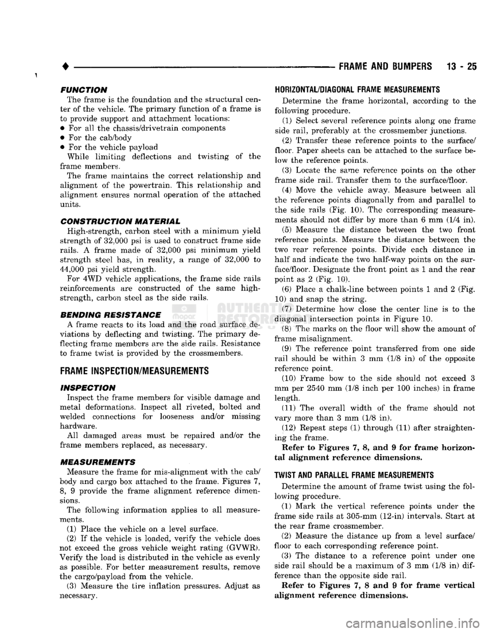
MEASUREMENTS Measure the frame for mis-alignment with the cab/
body and cargo box attached to the frame. Figures 7, 8, 9 provide the frame alignment reference dimen
sions.
The following information applies to all measure
ments.
(1) Place the vehicle on a level surface.
(2) If the vehicle is loaded, verify the vehicle does
not exceed the gross vehicle weight rating (GVWR).
Verify the load is distributed in the vehicle as evenly as possible. For better measurement results, remove
the cargo/payload from the vehicle.
(3) Measure the tire inflation pressures. Adjust as
necessary.
HORIZONTAL/DIAGONAL
FRAME MEASUREMENTS
Determine the frame horizontal, according to the
following procedure.
(1) Select several reference points along one frame
side rail, preferably at the crossmember junctions.
(2) Transfer these reference points to the surface/
floor. Paper sheets can be attached to the surface be low the reference points.
(3) Locate the same reference points on the other
frame side rail. Transfer them to the surface/floor.
(4) Move the vehicle away. Measure between all
the reference points diagonally from and parallel to
the side rails (Fig. 10). The corresponding measure ments should not differ by more than 6 mm (1/4 in).
(5)
Measure the distance between the two front
reference points. Measure the distance between the
two rear reference points. Divide each distance in
half and indicate the two half-way points on the sur
face/floor. Designate the front point as 1 and the rear
point as 2 (Fig. 10).
(6) Place a chalk-line between points 1 and 2 (Fig.
10) and snap the string.
(7) Determine how close the center line is to the
diagonal intersection points in Figure 10.
(8) The marks on the floor will show the amount of
frame misalignment.
(9) The reference point transferred from one side
rail should be within 3 mm (1/8 in) of the opposite
reference point.
(10) Frame bow to the side should not exceed 3
mm per 2540 mm (1/8 inch per 100 inches) in frame
length.
(11) The overall width of the frame should not
vary more than 3 mm (1/8 in). (12) Repeat steps (1) through (11) after straighten
ing the frame.
Refer to Figures 7, 8, and 9 for frame horizon
tal alignment reference dimensions.
TWIST
AND PARALLEL FRAME MEASUREMENTS
Determine the amount of frame twist using the fol
lowing procedure.
(1) Mark the vertical reference points under the
frame side rails at 305-mm (12-in) intervals. Start at
the rear frame crossmember.
(2) Measure the distance up from a level surface/
floor to each corresponding reference point. (3) The distance to a reference point under one
side rail should be a maximum of 3 mm (1/8 in)
dif
ference than the opposite side rail.
Refer to Figures 7, 8 and 9 for frame vertical
alignment reference dimensions.
Page 950 of 1502
•
PROPELLER
SHAFTS
16-5 A propeller shaft is properly phased when the yoke
ends are on the same plane or in line. A twisted
shaft will throw the yokes out of phase and cause a
noticeable vibration.
When taking universal joint angle measurements
or checking phasing with two piece shafts, consider
each shaft separately. On 4WD vehicles, the front shaft input (pinion shaft) angle has priority over the
caster angle.
Ideally the driveline system should have:
•
Angles that are in equal or opposite within 1
degree of each other
•
Have a 3 degree maximum operating angle
•
Have at least a 1/2 degree continuous operat
ing (propeller shaft) angle Engine speed (R.P.M.) is the main factor though in
determining maximum allowable operating angles.
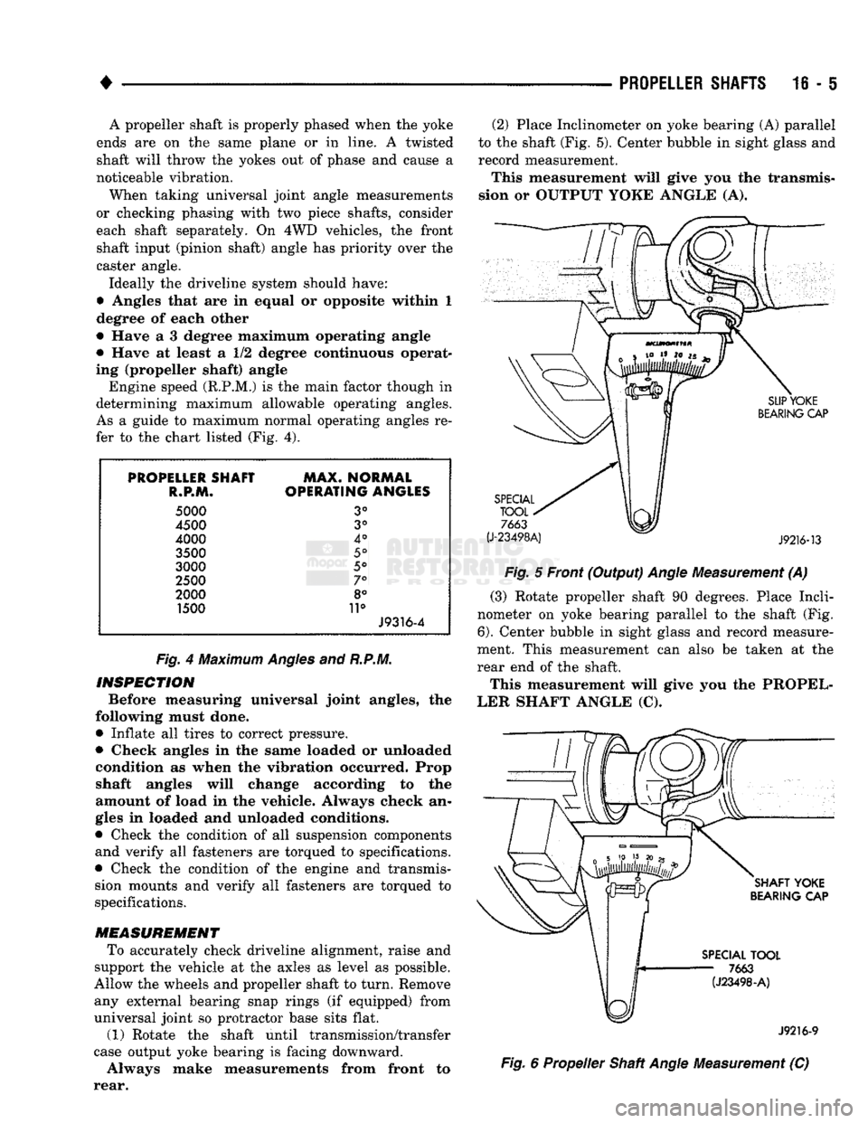
As a guide to maximum normal operating angles re
fer to the chart listed (Fig. 4).
PROPELLER
SHAFT
MAX*
NORMAL
R«P*JVi*
OPERATING
ANGLES
5000
3°
4500
3°
4000
4°
3500
5°
3000
5°
2500
7°
2000
8°
1500 11°
J9316-4
Fig.
4 Maximum
Angles
and
R.P.M.
INSPECTION
Before measuring universal joint angles, the
following must done.
•
Inflate all tires to correct pressure.
•
Check angles in the same loaded or unloaded condition as when the vibration occurred. Prop
shaft angles will change according to the
amount of load in the vehicle. Always check an
gles in loaded and unloaded conditions.
•
Check the condition of all suspension components
and verify all fasteners are torqued to specifications.
•
Check the condition of the engine and transmis
sion mounts and verify all fasteners are torqued to
specifications.
MEASUREMENT
To accurately check driveline alignment, raise and
support the vehicle at the axles as level as possible.
Allow the wheels and propeller shaft to turn. Remove any external bearing snap rings (if equipped) from
universal joint so protractor base sits flat.
(1) Rotate the shaft until transmission/transfer
case output yoke bearing is facing downward.
Always make measurements from front to
rear. (2) Place Inclinometer on yoke bearing (A) parallel
to the shaft (Fig. 5). Center bubble in sight glass and
record measurement.
This measurement will give you the transmis
sion or OUTPUT YOKE ANGLE (A).
Fig.
5 Front (Output)
Angle
Measurement (A)
(3) Rotate propeller shaft 90 degrees. Place Incli
nometer on yoke bearing parallel to the shaft (Fig.
6).
Center bubble in sight glass and record measure
ment. This measurement can also be taken at the
rear end of the shaft.
This measurement will give you the PROPEL
LER SHAFT ANGLE (C). J9216-9
Fig.
6 Propeller Shaft
Angle
Measurement (C)
Page 966 of 1502
•
STEERING
19-5 POWER STEERING SYSTEM DIAGNOSIS
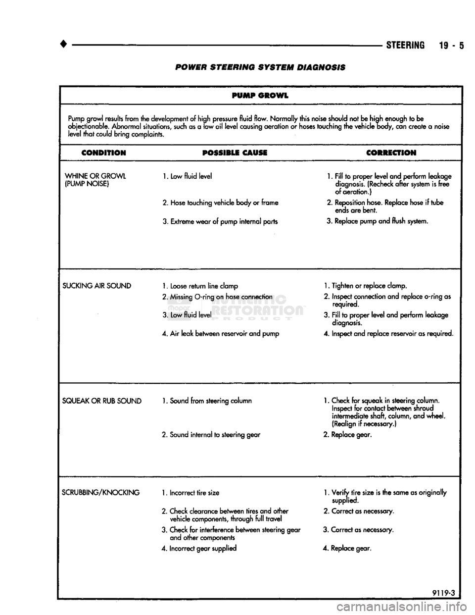
PUMP GROWL
Pump growl results from the development of high pressure fluid flow. Normally this noise should not be high enough to be
objectionable. Abnormal situations, such as a low oil level causing aeration or hoses touching the vehicle body, can create a noise level that could bring complaints.
CONDITION
POSSIBLE
CAUSE
CORRECTION
WHINE OR GROWL (PUMP NOISE)
1. Low
fluid level
2.
Hose touching vehicle body or frame
3.
Extreme wear of pump internal parts
1.
Fill to proper level and perform leakage
diagnosis. (Recheck after system is free
of aeration.)
2.
Reposition hose. Replace hose if tube ends are bent.
3.
Replace pump and
flush
system.
SUCKING
AIR
SOUND
1.
Loose return line clamp
2.
Missing
O-ring
on hose connection
3. Low
fluid level
4.
Air leak between reservoir and pump
1.
Tighten or replace clamp.
2.
Inspect connection and replace
o-ring
as required.
3.
Fill to proper level and perform leakage diagnosis.
4.
Inspect and replace reservoir as required.
SQUEAK
OR
RUB
SOUND
1.
Sound from steering column
2.
Sound internal to steering gear
1.
Check for squeak in steering column.
Inspect for contact between shroud
intermediate shaft, column, and wheel.
(Realign if necessary.)
2.
Replace gear.
SCRUBBING/KNOCKING
1.
Incorrect tire size
2.
Check clearance between tires and other vehicle components, through full travel
3.
Check for interference between steering gear and other components
4.
Incorrect gear supplied
1.
Verify tire size is the same as originally
supplied.
2.
Correct as necessary.
3.
Correct as necessary.
4.
Replace gear.
9119-3
Page 967 of 1502
19
- 6
STEERING
• POWER STEERING SYSTEM DIAGNOSIS
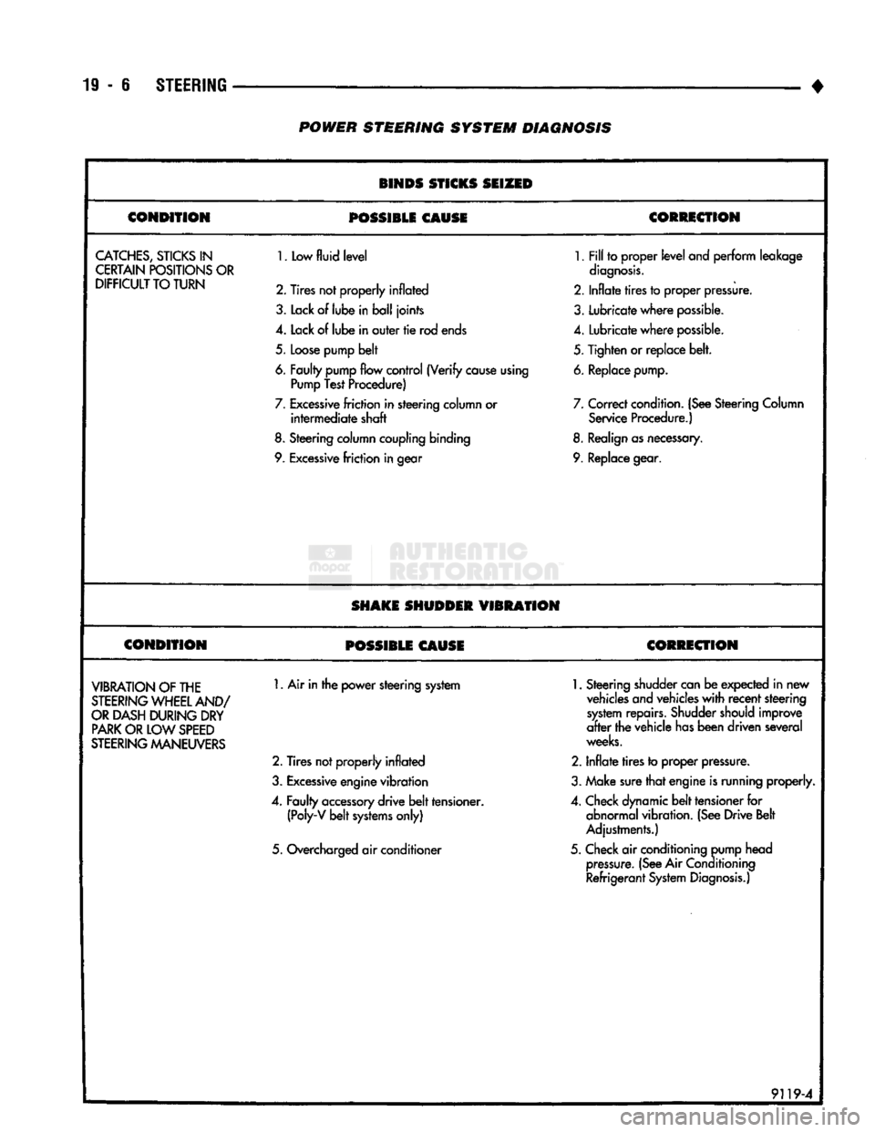
BINDS STICKS SEIZED
CONDITION
POSSIBLE
CAUSE CORRECTION
CATCHES,
STICKS
IN
CERTAIN POSITIONS OR
DIFFICULT
TO TURN
1.
Low
fluid level
2. Tires not properly
inflated
3.
Lack
of
lube
in ball joints
4.
Lack of lube in outer tie rod ends
5.
Loose pump belt
6. Faulty pump flow control (Verify cause using Pump Test Procedure)
7.
Excessive friction in steering column or intermediate shaft
8.
Steering column coupling binding
9. Excessive friction in gear
1.
Fill to proper level
and
perform leakage
diagnosis.
2.
Inflate tires to proper pressure.
3.
Lubricate where possible.
4.
Lubricate where possible.
5.
Tighten or replace belt.
6. Replace pump.
7.
Correct condition. (See Steering Column Service Procedure.)
8. Realign as necessary.
9. Replace gear.
SHAKE SHUDDER
VIBRATION
CONDITION
POSSIBLE CAUSE CORRECTION
VIBRATION
OF THE
STEERING
WHEEL AND/
OR
DASH DURING DRY
PARK
OR LOW
SPEED
STEERING
MANEUVERS
1.
Air in the power steering system
2.
Tires not properly inflated
3.
Excessive engine vibration
4.
Faulty accessory drive belt tensioner. (Poly-V belt systems only)
5.
Overcharged air conditioner
1.
Steering shudder can be expected in new
vehicles and vehicles with recent steering system repairs. Shudder should improve
after the vehicle has been driven several
weeks.
2.
Inflate tires to proper pressure.
3.
Make sure that engine is running properly.
4.
Check dynamic belt tensioner for abnormal vibration. (See Drive Belt
Adjustments.)
5.
Check air conditioning pump head pressure. (See Air
Conditioning
Refrigerant System Diagnosis.)
9119-4
Page 968 of 1502
•
STEERING
19 - 7 POWER STEERING SYSTEM DIAGNOSIS
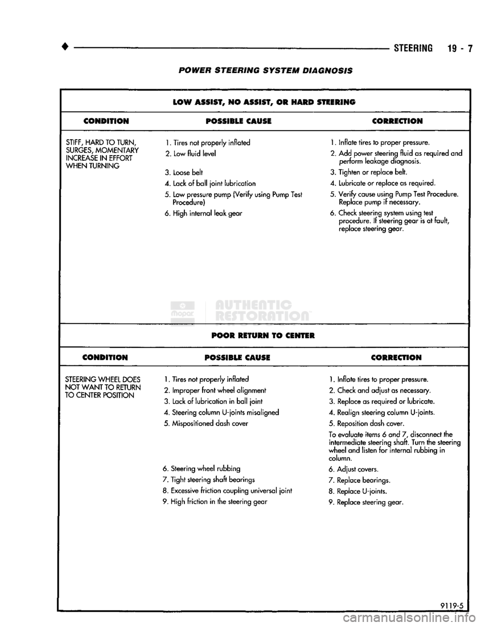
LOW
ASSIST,
NO
ASSIST,
OR
HARD
STEERING
CONDITION
POSSIBLE CAUSE
CORRECTION
STIFF,
HARD
TO TURN,
SURGES,
MOMENTARY
INCREASE
IN
EFFORT
WHEN
TURNING
1.
Tires not properly inflated
2. Low
fluid level
3.
Loose belt
1.
Inflate tires to proper pressure.
2.
Add power steering fluid as required and perform leakage diagnosis.
3.
Tighten or replace belt.
4.
Lack of ball joint lubrication
4.
Lubricate or replace as required.
5.
Low pressure pump (Verify using Pump Test Procedure)
5.
Verify cause using Pump Test Procedure.
Replace pump if necessary.
6. High internal leak gear 6. Check steering system using test
procedure. If steering gear is at fault, replace steering gear.
POOR RETURN
TO
CENTER
CONDITION POSSIBLE CAUSE CORRECTION
STEERING
WHEEL
DOES
NOT WANT
TO
RETURN
TO CENTER POSITION
1.
Tires not properly inflated
2.
Improper front wheel alignment
3.
Lack of lubrication in ball joint
1.
Inflate tires to proper pressure.
2.
Check and adjust as necessary.
3.
Replace as required or lubricate.
4.
Steering column U-joints misaligned
4.
Realign steering column U-joints.
5.
Mispositioned dash cover
5.
Reposition dash cover.
To
evaluate items 6 and 7, disconnect the intermediate steering shaft. Turn the steering
wheel and listen for internal rubbing in column.
6. Steering wheel rubbing 6. Adjust covers.
7.
Tight steering shaft bearings
7.
Replace bearings.
8. Excessive friction coupling universal joint 8. Replace U-joints.
9. High friction in the steering gear 9. Replace steering gear.
91195
Page 1171 of 1502
21
- 170
TRANSMISSION OVERHAUL—32RH
•
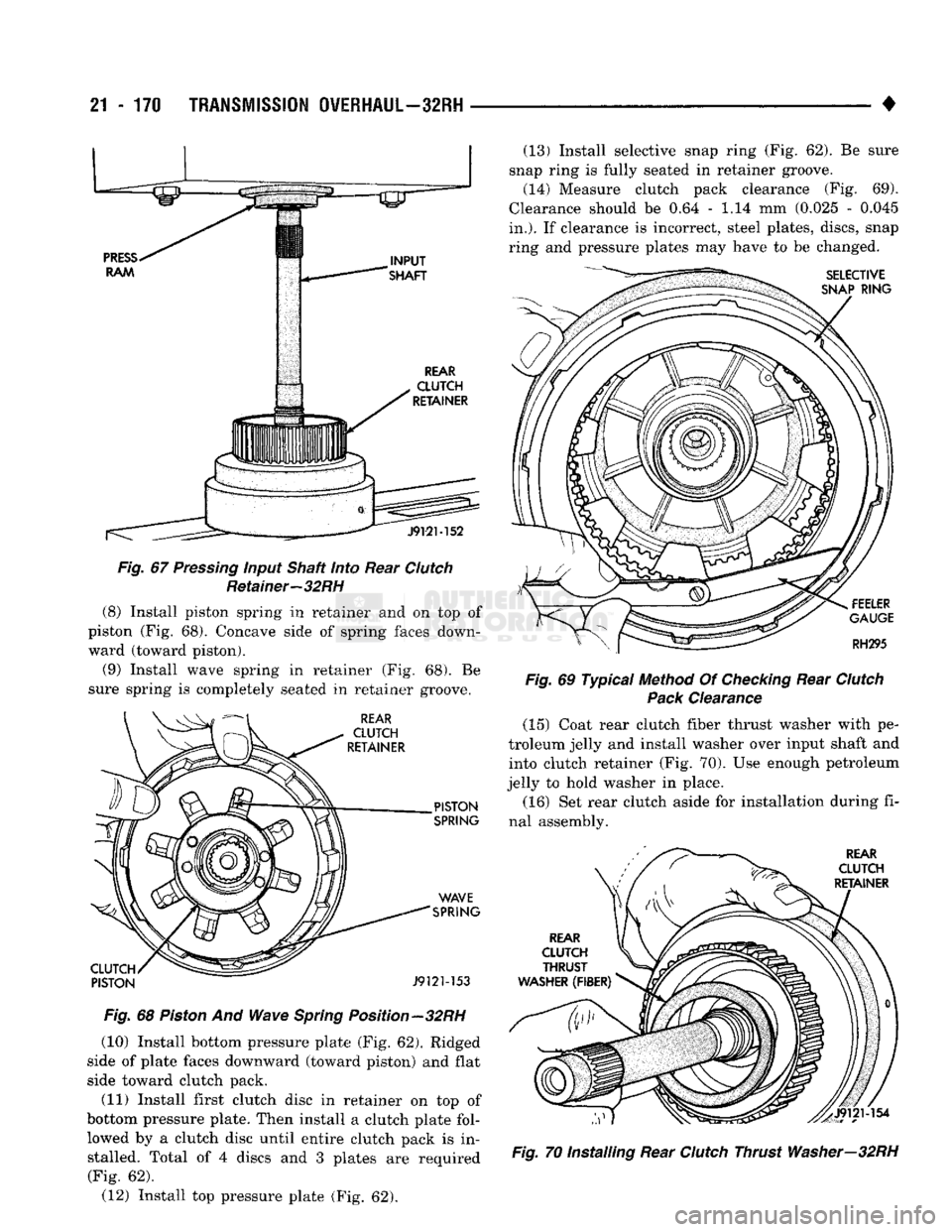
Fig.
67
Pressing
input Shaft
into
Rear
Clutch
Retainer—32RH (8) Install piston spring in retainer and on top of
piston (Fig. 68). Concave side of spring faces down ward (toward piston).
(9) Install wave spring in retainer (Fig. 68). Be
sure spring is completely seated in retainer groove.
Fig.
68
Piston
And Wave
Spring
Position—32RH
(10) Install bottom pressure plate (Fig. 62). Ridged
side of plate faces downward (toward piston) and flat
side toward clutch pack.
(11) Install first clutch disc in retainer on top of
bottom pressure plate. Then install a clutch plate fol lowed by a clutch disc until entire clutch pack is installed. Total of 4 discs and 3 plates are required (Fig. 62). (12) Install top pressure plate (Fig. 62). (13) Install selective snap ring (Fig. 62). Be sure
snap ring is fully seated in retainer groove. (14) Measure clutch pack clearance (Fig. 69).
Clearance should be 0.64 - 1.14 mm (0.025 - 0.045
in.).
If clearance is incorrect, steel plates, discs, snap
ring and pressure plates may have to be changed.
Fig.
69 Typical Method Of
Checking
Rear
Clutch
Pack
Clearance (15) Coat rear clutch fiber thrust washer with pe
troleum jelly and install washer over input shaft and into clutch retainer (Fig. 70). Use enough petroleum
jelly to hold washer in place.
(16) Set rear clutch aside for installation during fi
nal assembly.
Fig.
70 Installing Rear
Clutch
Thrust Washer—32RH
Page 1251 of 1502
21
- 250
TRANSMISSION 0VERHAUL-42RH
—
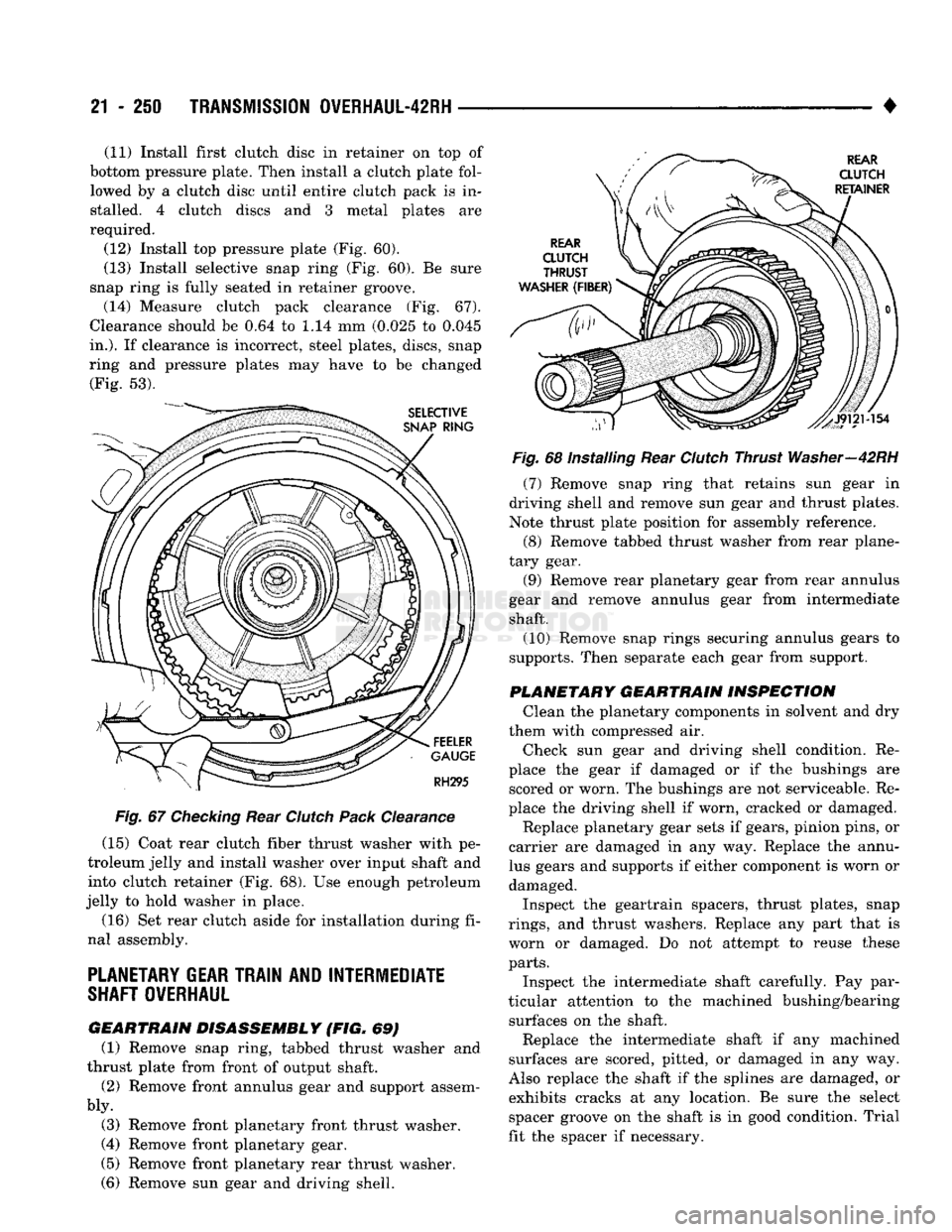
Fig.
67
Checking
Rear
Clutch
Pack
Clearance
(15) Coat rear clutch fiber thrust washer with pe
troleum jelly and install washer over input shaft and into clutch retainer (Fig. 68). Use enough petroleum
jelly to hold washer in place.
(16) Set rear clutch aside for installation during fi
nal assembly.
PLANETARY GEAR TRAIN AND INTERMEDIATE
SHAFT OVERHAUL
GEARTRAIN DISASSEMBLY (FIG* 69) (1) Remove snap ring, tabbed thrust washer and
thrust plate from front of output shaft. (2) Remove front annulus gear and support assem
bly. (3) Remove front planetary front thrust washer.
(4) Remove front planetary gear.
(5) Remove front planetary rear thrust washer.
(6) Remove sun gear and driving shell. •
Fig.
68 Installing Rear
Clutch
Thrust Washer—42RH (7) Remove snap ring that retains sun gear in
driving shell and remove sun gear and thrust plates.
Note thrust plate position for assembly reference. (8) Remove tabbed thrust washer from rear plane
tary gear.
(9) Remove rear planetary gear from rear annulus
gear and remove annulus gear from intermediate
shaft.
(10) Remove snap rings securing annulus gears to
supports. Then separate each gear from support.
PLANETARY GEARTRAIN INSPECTION Clean the planetary components in solvent and dry
them with compressed air. Check sun gear and driving shell condition. Re
place the gear if damaged or if the bushings are scored or worn. The bushings are not serviceable. Re
place the driving shell if worn, cracked or damaged.
Replace planetary gear sets if gears, pinion pins, or
carrier are damaged in any way. Replace the annu
lus gears and supports if either component is worn or
damaged.
Inspect the geartrain spacers, thrust plates, snap
rings,
and thrust washers. Replace any part that is worn or damaged. Do not attempt to reuse these
parts.
Inspect the intermediate shaft carefully. Pay par
ticular attention to the machined bushing/bearing surfaces on the shaft.
Replace the intermediate shaft if any machined
surfaces are scored, pitted, or damaged in any way.
Also replace the shaft if the splines are damaged, or exhibits cracks at any location. Be sure the select spacer groove on the shaft is in good condition. Trial
fit the spacer if necessary.
(11) Install first clutch disc in retainer on top of
bottom pressure plate. Then install a clutch plate fol lowed by a clutch disc until entire clutch pack is in
stalled. 4 clutch discs and 3 metal plates are
required.
(12) Install top pressure plate (Fig. 60).
(13) Install selective snap ring (Fig. 60). Be sure
snap ring is fully seated in retainer groove. (14) Measure clutch pack clearance (Fig. 67).
Clearance should be 0.64 to 1.14 mm (0.025 to 0.045
in.).
If clearance is incorrect, steel plates, discs, snap
ring and pressure plates may have to be changed (Fig. 53).
Page 1344 of 1502
•
NP205 TRANSFER
CASE
21 - 343 Leakage from other sources (engine, transmission,
etc.) can be blown back onto the transfer case by air
flow under the vehicle. A blocked transfer case vent
can also cause leakage at the shaft seals due to in
ternal pressure build up.
Overfilling the transfer case can force fluid out the
vent and be mistaken for a leak. Correct fluid level checking methods should prevent overfill problems.
Checking
Fluid Level The correct method of checking transfer case fluid
level requires that the vehicle be level.
If fluid level is checked with the vehicle parked on
the shop floor, be sure the floor area used is level. If a hoist is used, a drive-on, or swivel arm type is pre
ferred.
Allow the transfer case fluid to settle for a minute
or so before checking. Correct fluid level is to the
bottom edge of the fill plug hole.
HARD SHIFTING
Hard shifting is generally caused by:
• misadjusted or binding linkage
• loose linkage or driveline components
• torque loads caused by 4WD operation on hard
paved surfaces • improper shifting techniques
• lack of lubricant which caused internal wear and
damage.
Loose linkage or driveline components are a result
of improperly tightened, stripped, or missing fasten
ers.
Remember that loose crossmember and mounting
parts can also generate a hard shift condition.
Torque loads in the transfer case can cause hard
shifting or even prevent shifting. Such loads are gen
erally a product of extensive operation on hard,
paved surfaces in 4WD range, unequal size tires, or
by mismatched front/rear axle gear ratios.
Linkage adjustment should be performed as de
scribed in the service section. Improper shift and op
erating techniques can be corrected by instructing
the driver. Internal component damage will require
overhaul to correct.
Failure to lubricate the shift linkage at recom
mended intervals will cause the linkage to bind. If
bind is severe enough to cause hard shifting, the linkage will have to be removed in order to correct
the condition. The linkage can be soaked in auto
matic transmission fluid if necessary. The fluid will
break up accumulated rust and corrosion.
NOISE
Some transfer case operating noise is normal. The
rotating gear train can produce sounds that may be
come audible at higher speeds and loads. However,
unusual noise is an indicator that internal compo nents may be worn or damaged. Low lubricant levels are a frequent cause of noisy
operation. Insufficient lubricant will lead to over
heating, subsequent damage to bearing and gear sur
faces and hard shifting.
Transfer case bearing noise is higher in pitch than
gear noise. If the unit is noisy in 4WD range only,
the front shaft bearings are probably at fault. If the unit is noisy in all ranges, an overhaul will be nec
essary to locate the faulty bearing.
Gear noise is lower in pitch and usually most no
ticeable when engaged and under load. Gear noise in
4WD drive range only is an indicator that the front shaft gears are damaged. Noise in all ranges could be
the idler or drive gears. An overhaul will be neces sary to determine which is at fault.
Frequently, suspected transfer case noise may actu
ally originate from another driveline component. The
proximity of other driveline components can some
times make it difficult to pinpoint the noise source.
TRANSFER CASE OPERATIONAL CHECK
The transfer case should not be removed until di
agnosis indicates the unit has actually malfunc
tioned. If a transfer case problem is suspected, check and verify operation before attempting repair. A
transfer case operational check may reveal that a
problem is actually related to another driveline com ponent.
(1) Raise vehicle on a hoist that will allow all four
wheels to rotate. (2) Check lubricant level. If lubricant level is low,
check for leaks at the bearing and seal retainers,
yokes,
drain/fill plugs, PTO cover and vent. (3) If vehicle is equipped with locking hubs, en
gage hubs. (4) Start engine, shift transmission into gear and
operate transfer case in all ranges. Observe propeller shaft action, shift efforts and operational sound lev
els as follows: (a) Only the rear propeller shaft should rotate in
two-wheel drive. Both propeller shafts should both
rotate in four-wheel drive high and low ranges. (b) If the front propeller shaft did not rotate in
either four-wheel drive range, the transfer case shift components may be worn or damaged. Or, if
the front shaft did rotate but the front wheels did
not, check the front axle shift mechanism and the locking hubs (if equipped). (c) If both propeller shafts rotate in four-wheel
drive but the wheels on one axle did not rotate, the
problem is in the axle. (d) If neither propeller shaft rotates in any
range, the problem is in the transmission or trans fer case. To determine which component is at fault,
proceed to next step. (5) Determine if fault is with transfer case or
transmission as follows: