1993 CHEVROLET PLYMOUTH ACCLAIM ignition
[x] Cancel search: ignitionPage 387 of 2438

STARTER CONTROL CIRCUIT TESTS
The starter control circuit has:
² Starter solenoid
² Starter relay (Fig. 2)
² Neutral starting and back-up switch with auto-
matic transmissions
² Clutch pedal mounted starter interlock switch
with manual transmissions
² Ignition switch
² Battery
² All related wiring and connections
CAUTION: Before performing any starter tests, the
ignition system must be disabled.
² VEHICLES EQUIPPED WITH A CONVEN-
TIONAL DISTRIBUTOR: Disconnect coil wire from
distributor cap center tower. Secure wire to a good
ground to prevent engine from starting (Fig. 6).
² VEHICLES EQUIPPED WITH DIRECT IGNI-
TION SYSTEM: Unplug the coils electrical connector
(Fig. 7).
STARTER SOLENOID TEST
WARNING: CHECK TO ENSURE THAT THE TRANS-
MISSION IS IN PARK OR NEUTRAL WITH THE
PARKING BRAKE APPLIED
(1) Verify battery condition. Battery must be in
good condition with a full charge before performing
any starter tests. Refer to Battery Tests. (2) Perform this starter solenoid test BEFORE per-
forming the starter relay test. (3) Raise the vehicle.
(4) Perform a visual inspection of the starter/
starter solenoid for corrosion, loose connections or
faulty wiring. (5) Lower the vehicle.
(6) Locate the starter relay as follows:
² On AC, AG, AJ and AY Bodies the relay is located
in the Power Distribution Center. This Center is mounted near the front of the left front strut tower
(Fig. 13). The position of the starter relay within this
Center will be shown on the Center cover.
² On AA/AP Bodies the relay is located on the front
of the left front strut tower (Fig. 14).
(7) Remove the starter relay from the connector.
(8) Connect a remote starter switch or a jumper
wire between the battery positive post and terminal
87 on the starter relay connector. To decide the
starter relay terminal numbers, refer to the Starter
Relay Tests.
² If engine now cranks, starter/starter solenoid is
good. Go to the starter relay test.
² If engine does not crank with this test, or solenoid
chatters, check wiring and connectors from starter
Fig. 12 Test Positive Battery Cable Resistance
Fig. 13 Starter Relay LocationÐAC, AG, AJ, and AY Bodies
Fig. 14 Starter Relay LocationÐAA/AP Body
Ä BATTERY/STARTING/CHARGING SYSTEMS DIAGNOSTICS 8A - 15
Page 388 of 2438

relay to starter solenoid for loose or corroded connec-
tions. Particularly at starter terminals.
² Repeat test. If engine still fails to crank properly,
trouble is within starter or starter mounted solenoid,
and it must be removed for repairs. Refer to Group
8B, Battery/Starter/Generator Service, Starter re-
placement.
STARTER RELAY TEST
WARNING: CHECK TO ENSURE THAT THE TRANS-
MISSION IS IN PARK OR NEUTRAL WITH THE
PARKING BRAKE APPLIED
(1) Verify battery condition. Battery must be in
good condition with a full charge before performing
any starter tests. Refer to Battery Tests. (2) Perform the preceding starter solenoid tests
BEFORE performing starter relay tests. Refer to
Starter Solenoid Test. (3) Locate and remove the starter relay. For
starter relay locations, refer to Starter Solenoid Test
(Fig. 13 or 14). (4) After the starter relay has been located and re-
moved, refer to Starter Relay Tests (Fig. 15).
NEUTRAL STARTING AND BACK-UP SWITCH
AUTOMATIC TRANSMISSION ONLY
For electrical diagnostics, when checking starter
circuits, refer to Starter Relay Tests (Fig. 15). For replacement of switch, refer to Group 21, Tran-
saxle, Neutral Starting and Switch Replacement.
STARTER INTERLOCK SWITCHÐCLUTCH PEDAL MOUNTED
MANUAL TRANSMISSION ONLY
For electrical diagnostics, refer to the Starter Relay
Tests. For replacement and/or adjustment of the switch,
refer to Group 6, Manual Transaxle Clutch, Manual
Transaxle Starter Interlock Switch.
IGNITION SWITCH TEST
After testing the starter solenoid and relay, test ig-
nition switch and wiring. Refer to Group 8D, Ignition
Systems, or the Front Wheel Drive Car Wiring Dia-
grams Service Manual. Check all wiring for opens or
shorts, and all connectors for being loose or corroded.
BENCH TESTING STARTER SOLENOID
(1) Disconnect field coil wire from field coil termi-
nal (Fig. 16 or 17). (2) Check for continuity between solenoid terminal
and field coil terminal with a continuity tester. Con-
tinuity should be detected (Fig. 18 or 19). (3) Check for continuity between solenoid terminal
and solenoid housing (Fig. 20 or 21). Continuity
should be detected. If continuity is detected, solenoid
is good. (4) If continuity is not detected in either test, sole-
noid has an open circuit and is defective. If equipped
with:
² BOSCH STARTER: Replace the solenoid.
² NIPPONDENSO STARTER: Replace the starter
assembly.
8A - 16 BATTERY/STARTING/CHARGING SYSTEMS DIAGNOSTICS Ä
Page 391 of 2438

GENERATOR TEST PROCEDURES ON VEHICLE INDEX
page page
Charging System Diagnostics (Fig. 1) ......... 19
Current Output Test ...................... 19 Output Wire Resistance Test
................ 19
CHARGING SYSTEM DIAGNOSTICS (Fig. 1)
OUTPUT WIRE RESISTANCE TEST
The generator output wire resistance test shows
the amount of voltage drop across the generator out-
put wire between the generator B+ terminal and the
positive battery post.
PREPARATION
Before starting test, make sure the vehicle has a
fully charged battery. Tests and procedures to check
for a fully charged battery is shown in the Battery
section. (1) Turn the ignition switch OFF.
(2) Disconnect battery NEGATIVE cable.
(3) Disconnect the generator B+ output wire from
the generator output battery terminal (Fig. 2). (4) Connect a 0-150 ampere scale (DC) ammeter in
series between B+ terminal and output wire (Fig. 2
and 3). Connect positive lead to B+ terminal, and
negative lead to output wire. (5) Using o-18 volt scale voltmeter, connect the
positive lead to the disconnected (B+) output wire
(Fig. 2). Connect the negative lead to positive battery
post. (6) Remove fresh air hose between Powertrain
Control Module and air cleaner if necessary. (7) Connect jumper wire between a good ground
and K20 circuit terminal at the back of the genera-
tor.
CAUTION: Do not connect the A142 circuit terminal
(Fig. 2) to ground the Fusible link will burn.
(8) Connect an engine tachometer and connect bat-
tery negative cable. (10) Connect a volt/amp tester equipped with a
variable carbon pile rheostat between battery termi-
nals (Fig. 4).
Caution: Be sure the carbon pile is in OFF position
before connecting leads.
TEST
(1) Start engine. Immediately after starting, re-
duce engine speed to idle. (2) Adjust engine speed and carbon pile to main-
tain 20 amperes flowing in the circuit. Observe volt-
meter reading. Voltmeter reading should not exceed
0.5 volts.
RESULTS
If a higher voltage drop is shown, inspect, clean
and tighten all connections between generator B+
terminal and battery positive post. A voltage drop
test may be performed at each connection to locate a
connection with excessive resistance. If resistance
tests are satisfactory, reduce engine speed, turn off
carbon pile, and turn off ignition switch. (1) Disconnect battery negative cable.
(2) Remove test ammeter, voltmeter, carbon pile,
and tachometer. (3) Remove jumper wire.
(4) Connect generator output wire to generator B+
terminal. (5) Connect battery negative cable.
(6) Connect fresh air hose between Powertrain
Control Module and air cleaner if removed.
CURRENT OUTPUT TEST
The current output test decides whether the gener-
ator can deliver its rated current output. For gener-
ator identification and output amperage
specifications, refer to Generator Specifications. For generator maximum voltage at individual tem-
peratures, refer to Generator Output Voltage Specifi-
cations.
PREPARATION
Before starting any tests, make sure the vehicle
has a fully charged battery. Tests and procedures to
check for a fully charged battery is shown in Battery
section. (1) Disconnect battery negative cable.
(2) Disconnect output wire at the B+ terminal
(Figs. 2 and 5). (3) Connect a 0-150 ampere scale (DC) ammeter in
series between the B+ terminal and output wire.
Connect Positive lead to B+ terminal and negative
lead to output wire. (4) Using 0-18 voltmeter, connect positive lead to
B+ terminal (Figs. 2 and 5). Connect negative lead
to a good ground.
Ä BATTERY/STARTING/CHARGING SYSTEMS DIAGNOSTICS 8A - 19
Page 395 of 2438

FAULT CODESÐON BOARD DIAGNOSTICS INDEX
page page
Diagnostic Testing Using Fault Codes ......... 24
Drb II Diagnostic Tester ................... 24 General Description/Information
.............. 23
GENERAL DESCRIPTION/INFORMATION
Another way of diagnosing charging system prob-
lems can be accomplished using the On Board Diag-
nostic System Fault Codes. A Fault Code shows a potential problem in a mon-
itored circuit, or a condition caused by a faulty component. A
Fault Code can be retrieved by turning the ignition
switch ON-OFF-ON-OFF-ON without starting the
engine, and counting the number of flashes of the
Malfunction Indicator (CHECK ENGINE) Lamp in
the instrument cluster.
EXAMPLES:
² If the Malfunction Indicator (Check Engine) Lamp
flashes four times, pauses, and flashes one more
time, a Code 41 is shown. The first set of four flashes
indicates number four. The second set of one flash in-
dicates one.
² If the Malfunction Indicator (Check Engine) Lamp
flashes four times, pauses, and flashes six more
times, a Code 46 is shown. The first set of four
flashes indicates number four. The second set of six
flashes indicates six.
² If the Malfunction Indication (Check Engine)
Lamp flashes four times, pauses, and flashes seven
more times, a Code 47 is shown. The first set of four
flashes indicates number four. The second set of
seven flashes indicates seven. POWERTRAIN CONTROL MODULE
The Powertrain Control Module is equipped with
On Board Diagnostic features and monitors all en-
gine control circuits during a run/drive period. If a
circuit or system does not perform properly, the pow-
ertrain control module will file in memory a preset
Fault Code. This can be used to help in diagnosing a
problem. After 50 to 100 ignition switch ON/RUN cy-
cles, the memory will be erased if the fault does not
reoccur. The Powertrain Control Module is located in the
engine compartment outboard of the battery (Fig. 7).
Refer to Fig. 8 Generator Fault Codes Chart for re-
lationships of generator/charging system Fault Code
numbers.
Fig. 7 Powertrain Control Module
Ä BATTERY/STARTING/CHARGING SYSTEMS DIAGNOSTICS 8A - 23
Page 403 of 2438

BATTERY/STARTER/GENERATOR SERVICE
CONTENTS
page page
BATTERY REMOVAL, INSTALLATION AND SERVICE ............................. 1
GENERATOR ............................ 9 SPECIFICATIONS
....................... 12
STARTER ............................... 4
BATTERY REMOVAL, INSTALLATION AND SERVICE
GENERAL INFORMATION
This first section will cover Battery replacement and
service procedures only. For Battery diagnostic proce-
dures, refer to Group 8A, Battery/Starting/Charging
Systems Diagnostics. Factory installed batteries (Fig. 1) do not have re-
movable battery cell caps. Water cannot be added to
factory installed battery. Battery is sealed, except for
small vent holes in the top. Chemical composition
inside the battery produces an extremely small amount
of gases at normal charging voltages. The factory
installed battery is equipped with a test indicator that
displays a colored ball to show the battery's state of
charge.
² Green Indicator = Full charge
² Black Indicator = Discharged
² Yellow Indicator = Battery replacement required.
BATTERY VISUAL INSPECTION AND SERVICE
(1) Make sure ignition switch is in OFF position and
all accessories are OFF. (2) Disconnect and remove the battery cable termi-
nals from the battery posts. Remove negative cable
first (Fig. 2). WARNING: TO PROTECT THE HANDS FROM BAT-
TERY ACID, A SUITABLE PAIR OF HEAVY DUTY
RUBBER GLOVES, NOT THE HOUSEHOLD TYPE,
SHOULD BE WORN WHEN REMOVING OR SERVIC-
ING A BATTERY. SAFETY GLASSES ALSO SHOULD
BE WORN.
(3) Lift battery heat shield off battery, if equipped
(Fig. 3). (4) Remove battery hold down nut and clamp.
Fig. 1 Maintenance Free Battery
Fig. 2 Remove Battery Cables
Fig. 3 Battery Hold-Down
Ä BATTERY/STARTER/GENERATOR SERVICE 8B - 1
Page 406 of 2438

STARTER INDEX
page page
General Information ........................ 4
Neutral Starter and Back-Up Switch ........... 8
Starter Component Replacement .............. 5
Starter Interlock Switch: Clutch Pedal Mounted/ Manual Transmission Only ................. 7 Starter Motor Replacement
.................. 4
Starting System ........................... 4
Supply Circuit and Control Circuit ............. 4
GENERAL INFORMATION
This section will cover Starter replacement and
service procedures only. For starter diagnostic proce-
dures, refer to Group 8A, Battery/Starting/Charging
Systems Diagnostics.
STARTING SYSTEM
The starting system has:
² Ignition switch
² Starter relay
² Neutral starting and back-up switch with auto-
matic transmissions
² Clutch pedal mounted starter interlock switch
with manual transmissions
² Wiring harness
² Battery
² Starter motor with an integral solenoid
BOSCH STARTERS
²A Bosch permanent magnet starter motor is avail-
able on 2.2L, 2.5L and 3.0L engines on all vehicles.
A planetary gear train transmits power between
starter motor and pinion shaft. The fields consist of
six permanent magnets.
NIPPONDENSO STARTERS
² A Nippondenso reduction gear-field coil starter
motor is available on 3.0L, 3.3L and 3.8L engines.
SUPPLY CIRCUIT AND CONTROL CIRCUIT
Both starter systems consist of two separate cir-
cuits:
² A high amperage supply to feed the starter motor.
² A low amperage circuit to control the starter sole-
noid. For additional information on starter motor supply
and control circuits, refer to Group 8A, Battery/Start-
ing/Charging Systems Diagnostics.
STARTER MOTOR REPLACEMENT
BOSCH STARTERÐ2.2L/2.5L ENGINE
(1) Disconnect battery negative cable (Fig. 1).
(2) Raise vehicle. (3) Remove heat shield clip from the starter and
heat shield is clipped to starter (Fig. 2). For easier
servicing, do not remove the wiring from starter at
this time.
(4) Remove two bolts and one nut attaching starter
to engine (Fig. 3). (5) Remove starter/starter solenoid assembly from
engine. Position the starter to gain access to the wir-
ing connectors. (6) Disconnect the positive battery cable and wir-
ing at the starter. (7) Remove the starter from vehicle.
Fig. 1 Remove or Install Battery Cable
Fig. 2 Starter Heat ShieldÐ4 Cylinder Engines
8B - 4 BATTERY/STARTER/GENERATOR SERVICE Ä
Page 417 of 2438

OVERHEAD CONSOLE
CONTENTS
page page
AA BODY .............................. 1
AC AND AY BODY ....................... 6 AG AND AJ BODIES
.................... 13
AP BODY ............................. 21
GENERAL INFORMATION AA BODY
INDEX
page page
Ambient Temperature Sensor ................ 6
Compass Calibration ....................... 2
Compass Diagnostics ...................... 5
Compass Module Replacement ............... 6
Demagnetizing Procedure ................... 4 Map Reading Lamps
....................... 1
Overhead Console Replacement .............. 5
Self-Diagnostic Test ....................... 5
Thermometer and Compass Operation ......... 1
Variance ................................ 2
MAP READING LAMPS
The map reading and rear passenger lamps are
turned on and off by pressing their individual switch
marked LAMP. These same lamps also serve as cour-
tesy lamps whenever a door is opened, the illumi-
nated entry system is activated, or the headlamp
switch is turned fully clockwise.
LAMP REPLACEMENT
(1) Remove lens by inserting a large paper clip or
wire, with a hook on the end, into the hole in the
lens and pull downward (Fig. 1).
(2) Remove lamp by pulling firmly toward front of
vehicle. (3) Install new lamp by pushing firmly into recep-
tacle. (4) Snap lens into position taking care to orient
the tabs on the lens with the slots in the housing and
snap into position.
LAMP TEST
(1) Close vehicle doors.
(2) Press each lamp switch button (Fig.2). Right
hand button should light passenger side lamp and
left hand button should light drivers side lamp front
or rear. (3) If any of the lamps fail to illuminate, open ve-
hicle doors: (a) If lamp does not illuminate check for a
burned out lamp. If lamp is OK, check fuse and
wire connectors. (b) If lamp illuminates when doors are open
check switch.
THERMOMETER AND COMPASS OPERATION
The ignition switch must be in the ON or ACCES-
SORY position before the temperature and compass
reading can be displayed. The Comp/Temp switch, lo-
cated left of the display module, turns the display on
and off. The US/Metric switch, located right of the dis-
play, changes the temperature reading from Fahrenheit
to Celsius. Should the compass blank out and the CAL
symbol only light, demagnetizing may be necessary.
The compass is a flux-gate system which, is inte-
gral to the console. The temperature readout is con-
nected to a thermistor sensor which, located on the
front lower radiator closure panel.Fig. 1 Overhead Console Lens Removal
Ä OVERHEAD CONSOLE 8C - 1
Page 418 of 2438

When the vehicle is standing still, engine compart-
ment temperature may be radiated to the tempera-
ture sensor. Therefore the most accurate ambient
temperature readings are displayed when the vehicle
is moving in a forward motion. When the ignition switch is turned off the last dis-
played temperature reading stays in memory. When
the ignition switch is turned on again the thermom-
eter will display the memory temperature for 1
minute; then update the display to the actual tem-
perature within 5 minutes. Refer to Compass and
Thermometer Diagnosis (Fig. 3).
COMPASS CALIBRATION
The compass unit automatically calibrates itself as
the vehicle is driven; therefore, no calibration should be
required. When the compass is first powered up, the
CAL light on the display should be on. The CAL light
will go off and the compass will be accurate after the
vehicle completes one to three complete circles.
Do not attempt to set the compass near large metal
objects, such as, other vehicles, large buildings, or
bridges. If the vehicle's compass headings are inaccurate,
the compass also can be manually calibrated using
the following procedures: (1) Depress and hold down both the Comp/Temp
button and the U.S./Metric button. (2) The display will go off and after 5 seconds the
VAR light will come on. Continue to hold both but-
tons down. (3) In approximately 10 seconds, the CAL light
will come on. Release both buttons and the display
will show the heading and outside temperature. (4) Release buttons the CAL light will then go off,
showing the compass is calibrated. (5) The variation may need to be adjusted. The
variation is the difference between magnetic north
and true north. To set variation refer the to Varia-
tion Setting Procedure. If the compass portion of the display is not lit or
compass readings are not accurate after calibration.
The vehicle may have too much magnetism for the
compass to be accurate or the compass circuitry is
not working properly. Refer to Variance Procedure,
Demagnetizing Procedure and/or Compass Diagnos-
tics.VARIANCE
Variance is the difference between magnetic North
and geographic North. In some areas the difference
between magnetic and geographic north is great
enough to cause the compass to give false readings. If
this occurs, the variance must be set.
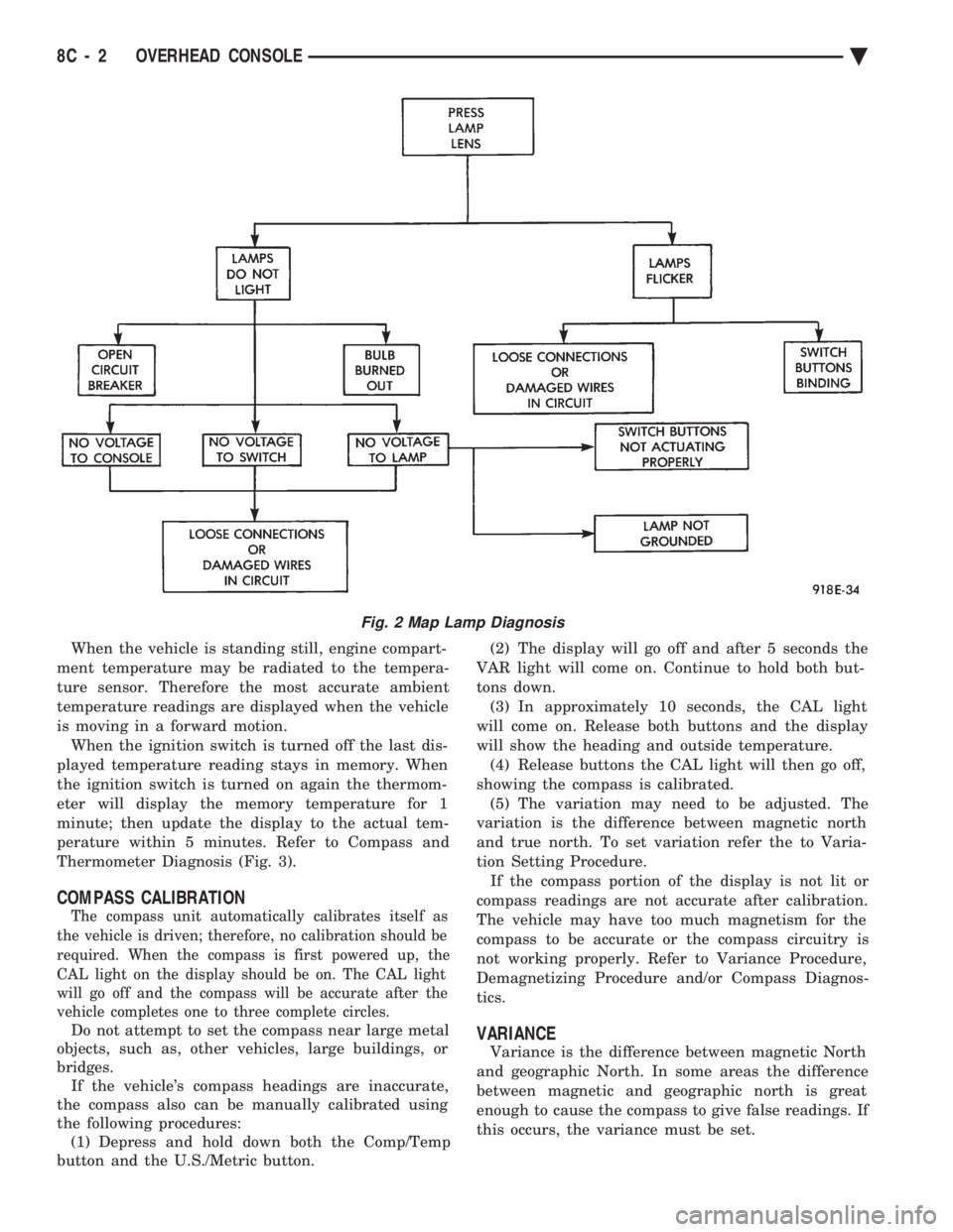
Fig. 2 Map Lamp Diagnosis
8C - 2 OVERHEAD CONSOLE Ä