1993 CHEVROLET PLYMOUTH ACCLAIM tow
[x] Cancel search: towPage 731 of 2438
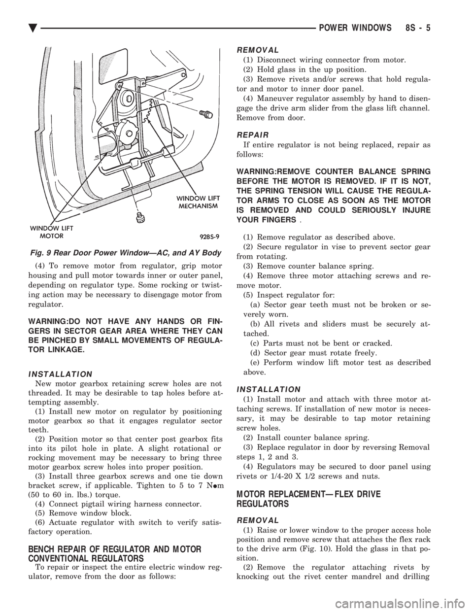
(4) To remove motor from regulator, grip motor
housing and pull motor towards inner or outer panel,
depending on regulator type. Some rocking or twist-
ing action may be necessary to disengage motor from
regulator.
WARNING:DO NOT HAVE ANY HANDS OR FIN-
GERS IN SECTOR GEAR AREA WHERE THEY CAN
BE PINCHED BY SMALL MOVEMENTS OF REGULA-
TOR LINKAGE.
INSTALLATION
New motor gearbox retaining screw holes are not
threaded. It may be desirable to tap holes before at-
tempting assembly. (1) Install new motor on regulator by positioning
motor gearbox so that it engages regulator sector
teeth. (2) Position motor so that center post gearbox fits
into its pilot hole in plate. A slight rotational or
rocking movement may be necessary to bring three
motor gearbox screw holes into proper position. (3) Install three gearbox screws and one tie down
bracket screw, if applicable. Tighten to 5 to 7 N Im
(50 to 60 in. lbs.) torque. (4) Connect pigtail wiring harness connector.
(5) Remove window block.
(6) Actuate regulator with switch to verify satis-
factory operation.
BENCH REPAIR OF REGULATOR AND MOTOR
CONVENTIONAL REGULATORS
To repair or inspect the entire electric window reg-
ulator, remove from the door as follows:
REMOVAL
(1) Disconnect wiring connector from motor.
(2) Hold glass in the up position.
(3) Remove rivets and/or screws that hold regula-
tor and motor to inner door panel. (4) Maneuver regulator assembly by hand to disen-
gage the drive arm slider from the glass lift channel.
Remove from door.
REPAIR
If entire regulator is not being replaced, repair as
follows:
WARNING:REMOVE COUNTER BALANCE SPRING
BEFORE THE MOTOR IS REMOVED. IF IT IS NOT,
THE SPRING TENSION WILL CAUSE THE REGULA-
TOR ARMS TO CLOSE AS SOON AS THE MOTOR
IS REMOVED AND COULD SERIOUSLY INJURE
YOUR FINGERS .
(1) Remove regulator as described above.
(2) Secure regulator in vise to prevent sector gear
from rotating. (3) Remove counter balance spring.
(4) Remove three motor attaching screws and re-
move motor. (5) Inspect regulator for:(a) Sector gear teeth must not be broken or se-
verely worn. (b) All rivets and sliders must be securely at-
tached. (c) Parts must not be bent or cracked.
(d) Sector gear must rotate freely.
(e) Perform window lift motor test as described
above.
INSTALLATION
(1) Install motor and attach with three motor at-
taching screws. If installation of new motor is neces-
sary, it may be desirable to tap motor retaining
screw holes. (2) Install counter balance spring.
(3) Replace regulator in door by reversing Removal
steps 1, 2 and 3. (4) Regulators may be secured to door panel using
rivets or 1/4-20 X 1/2 screws and nuts.
MOTOR REPLACEMENTÐFLEX DRIVE
REGULATORS
REMOVAL
(1) Raise or lower window to the proper access hole
position and remove screw that attaches the flex rack
to the drive arm (Fig. 10). Hold the glass in that po-
sition. (2) Remove the regulator attaching rivets by
knocking out the rivet center mandrel and drilling
Fig. 9 Rear Door Power WindowÐAC, and AY Body
Ä POWER WINDOWS 8S - 5
Page 733 of 2438
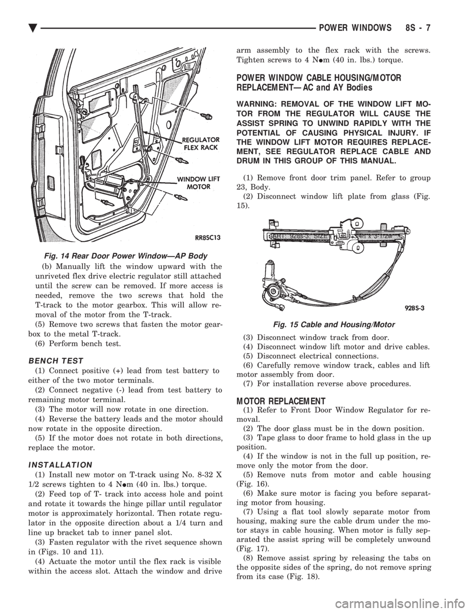
(b) Manually lift the window upward with the
unriveted flex drive electric regulator still attached
until the screw can be removed. If more access is
needed, remove the two screws that hold the
T-track to the motor gearbox. This will allow re-
moval of the motor from the T-track.
(5) Remove two screws that fasten the motor gear-
box to the metal T-track. (6) Perform bench test.
BENCH TEST
(1) Connect positive (+) lead from test battery to
either of the two motor terminals. (2) Connect negative (-) lead from test battery to
remaining motor terminal. (3) The motor will now rotate in one direction.
(4) Reverse the battery leads and the motor should
now rotate in the opposite direction. (5) If the motor does not rotate in both directions,
replace the motor.
INSTALLATION
(1) Install new motor on T-track using No. 8-32 X
1/2 screws tighten to 4 N Im (40 in. lbs.) torque.
(2) Feed top of T- track into access hole and point
and rotate it towards the hinge pillar until regulator
motor is approximately horizontal. Then rotate regu-
lator in the opposite direction about a 1/4 turn and
line up bracket tab to inner panel slot. (3) Fasten regulator with the rivet sequence shown
in (Figs. 10 and 11). (4) Actuate the motor until the flex rack is visible
within the access slot. Attach the window and drive arm assembly to the flex rack with the screws.
Tighten screws to 4 N Im (40 in. lbs.) torque.
POWER WINDOW CABLE HOUSING/MOTOR
REPLACEMENTÐAC and AY Bodies
WARNING: REMOVAL OF THE WINDOW LIFT MO-
TOR FROM THE REGULATOR WILL CAUSE THE
ASSIST SPRING TO UNWIND RAPIDLY WITH THE
POTENTIAL OF CAUSING PHYSICAL INJURY. IF
THE WINDOW LIFT MOTOR REQUIRES REPLACE-
MENT, SEE REGULATOR REPLACE CABLE AND
DRUM IN THIS GROUP OF THIS MANUAL.
(1) Remove front door trim panel. Refer to group
23, Body. (2) Disconnect window lift plate from glass (Fig.
15).
(3) Disconnect window track from door.
(4) Disconnect window lift motor and drive cables.
(5) Disconnect electrical connections.
(6) Carefully remove window track, cables and lift
motor assembly from door. (7) For installation reverse above procedures.
MOTOR REPLACEMENT
(1) Refer to Front Door Window Regulator for re-
moval. (2) The door glass must be in the down position.
(3) Tape glass to door frame to hold glass in the up
position. (4) If the window is not in the full up position, re-
move only the motor from the door. (5) Remove nuts from motor and cable housing
(Fig. 16). (6) Make sure motor is facing you before separat-
ing motor from housing. (7) Using a flat tool slowly separate motor from
housing, making sure the cable drum under the mo-
tor stays in cable housing. When motor is fully sep-
arated the assist spring will be completely unwound
(Fig. 17). (8) Remove assist spring by releasing the tabs on
the opposite sides of the spring, do not remove spring
from its case (Fig. 18).
Fig. 14 Rear Door Power WindowÐAP Body
ART: 928s-3; SIZE (1) = 1-3/4h x 3-1/2w
Fig. 15 Cable and Housing/Motor
Ä POWER WINDOWS 8S - 7
Page 1568 of 2438
The MOPAR Silicone Rubber Adhesive Sealant
gasket material or equivalent should be applied in a
continuous bead approximately 3mm (0.120 inch) in
diameter. All mounting holes must be circled. For
corner sealing, a 3.17 or 6.35 mm (1/8 or 1/4 inch.)
drop is placed in the center of the gasket contact
area. Uncured sealant may be removed with a shop
towels. Components should be torqued in place while
the sealant is still wet to the touch (within 10 min-
utes). The usage of a locating dowel is recommended
during assembly to prevent smearing of material off
location.
CRANKSHAFT SPROCKET BOLT ACCESS PLUG
An Access plug is located in the right inner fender
shield. Remove the plug and insert proper size
socket, extension and rachet, when crankshaft rota-
tion is necessary.
ENGINE PERFORMANCE
If a loss of performance is noticed, ignition timing
should be checked. If ignition timing is retarded by
9, 18 or 27É indicating 1, 2 or 3 (timing belt or chain)
teeth may have skipped, then, camshaft and acces-
sory shaft timing with the crankshaft should be
checked. Refer to Engine Timing Sprockets and Oil
Seals of the Engine Section. To provide best vehicle performance and lowest ve-
hicle emissions, it is most important that the tune-up
be done accurately. Use the specifications listed on
the Vehicle Emission Control Information label
found in the engine compartment. (1) Test cranking amperage draw. See Starting
Motor Cranking Amperage Draw Electrical Section
of this manual. (2) Tighten the intake manifold bolts to specifica-
tions. (3) Perform cylinder compression test.(a) Check engine oil level and add oil if neces-
sary. (b) Drive the vehicle until engine reaches normal
operating temperature. (c) Select a route free from traffic and other
forms of congestion, observe all traffic laws, and ac-
celerate through the gears several times briskly.
CAUTION: Do not overspeed the engine. The higher
engine speed may help clean out valve seat deposits
which can prevent accurate compression readings.
(d) Remove all spark plugs from engine. As
spark plugs are being removed, check electrodes for
abnormal firing indicators fouled, hot, oily, etc.
Record cylinder number of spark plug for future
reference. (e) Disconnect coil wire from distributor and se-
cure to good ground to prevent a spark from start- ing a fire (Conventional Ignition System). For Direct
Ignition System DIS disconnect the coil connector. (f) Be sure throttle blade is fully open during the
compression check. (g) Insert compression gage adaptor into the #1
spark plug hole in cylinder head. Crank engine until
maximum pressure is reached on gage. Record this
pressure as #1 cylinder pressure. (h) Repeat Step G for all remaining cylinders.
(i) Compression should not be less than (689kPa)
100 psi and not vary more than 25 percent from
cylinder to cylinder. (j) If one or more cylinders have abnormally low
compression pressures, repeat steps 3b through 3h. (k) If the same cylinder or cylinders repeat an
abnormally low reading on the second compression
test, it could indicate the existence of a problem in
the cylinder in question.
The recommended compression pressures are
to be used only as a guide to diagnosing engine
problems. An engine should not be disassembled
to determine the cause of low compression un-
less some malfunction is present. (4) Clean or replace spark plugs as necessary and
adjust gap as specified in Electrical Group 8. Tighten to
specifications. (5) Test resistance of spark plug cables. Refer to
Ignition System Secondary Circuit Inspection Electri-
cal Section Group 8. (6) Inspect the primary wire. Test coil output volt-
age, primary and secondary resistance. Replace parts
as necessary. Refer to Ignition System and make nec-
essary adjustment. (7) Ignition timing should be set to specifications.
(See Specification Label in engine compartment). (8) Test fuel pump for pressure and vacuum. Refer to
Fuel System Group 14, Specifications. (9) The air filter elements should be replaced as
specified in Lubrication and Maintenance, Group 0. (10) Inspect crankcase ventilation system as out
lined in Lubrication and Maintenance, Group 0. For
emission controls see Emission Controls Group 25 for
service procedures. (11) Inspect and adjust accessory belt drives refer-
ring to Accessory Belt Drive in Cooling System, Group
7 for proper adjustments. (12) Road test vehicle as a final test.
HONING CYLINDER BORES
Before honing, stuff plenty of clean shop towels
under the bores, over the crankshaft to keep abrasive
materials from entering crankcase area. (1) Used carefully, the cylinder bore resizing hone
C-823 equipped with 220 grit stones, is the best tool for
this job. In addition to deglazing, it will reduce taper
and out-of-round as well as removing light
9 - 2 ENGINE Ä
Page 1570 of 2438
REMOVE ALL SHIMS BEFORE REASSEM-
BLING ENGINE ALTERNATIVE METHOD Ð With the weight of
the crankshaft being supported by a jack under the
counterweight adjacent to the bearing being checked. (3) Place a piece of Plastigage across the entire
width of the bearing shell in the cap approximately
6.35 mm (1/4 inch) off center and away from the oil
holes (Fig. 2). (In addition, suspect areas can be
checked by placing the Plastigage in the suspect area).
Torque the bearing cap bolts of the bearing being
checked to the proper specifications. (4) Remove the bearing cap and compare the width
of the flattened Plastigage (Fig. 3) with the metric scale
provided on the package. Locate the band closest to the
same width. This band shows the amount of clearance
in thousandths of a millimeter. Differences in readings
between the ends indicate the amount of taper present.
Record all readings taken. Refer to Engine Specifica-
tions. Plastic-Gage generally is accompanied by
two scales. One scale is in inches, the other is a
metric scale. (5) Plastigage is available in a variety of clearance
ranges. The 0.025-0.076mm (.001-.003 inch) is usually
the most appropriate for checking engine bearing
proper specifications.
CONNECTING ROD BEARING CLEARANCE
Engine crankshaft bearing clearances can be deter-
mined by use of Plastigage or equivalent. The following
is the recommended procedure for the use of Plasti-
gage: (1) Rotate the crankshaft until the connecting rod to
be checked is at the bottom of its stroke. (2) Remove oil film from surface to be checked.
Plastigage is soluble in oil. (3) Place a piece of Plastigage across the entire
width of the bearing shell in the bearing cap approxi-
mately 6.35 mm (1/4 inch.) off center and away from
the oil hole (Fig. 2). In addition, suspect areas can be
checked by placing plastigage in the suspect area. (4) Before assembling the rod cap with Plastigage in
place, the crankshaft must be rotated until the con-
necting being checked starts moving toward the top of
the engine. Only then should the cap be assembled and
torqued to specifications. Do not rotate the crank-
shaft while assembling the cap or the Plastigage
may be smeared, giving inaccurate results. (5) Remove the bearing cap and compare the width
of the flattened Plastigage (Fig. 3) with the metric
scale provided on the package. Locate the band closest
to the same width. This band shows the amount
of clearance in thousandths of a millimeter. Differences
in readings between the ends indicate the amount
of taper present. Record all readings taken.
Refer to Engine Specifications. Plastigage generally is accompanied by two scales. One scale is in
inches, the other is a metric scale. (6) Plastigage is available in a variety of clearance
ranges. The 0.025-0.076mm (.001-.003 inch) is usually
the most appropriate for checking engine bearing
proper specifications.
LASH ADJUSTER (TAPPET) NOISE DIAGNOSIS
A tappet-like noise may be produced from several
items. Check the following items. (1) Engine oil level too high or too low. This may
cause aerated oil to enter the adjusters and cause them
to be spongy. (2) Insufficient running time after rebuilding cylin-
der head. Low speed running up to 1 hour may be
required. During this time, turn engine off and let set for a few
minutes before restarting. Repeat this several times
after engine has reached normal operating tempera-
ture. (3) Low oil pressure.
(4) The oil restrictor pressed into the vertical oil
passage to the cylinder head of Balance Shaft Engines
Only is plugged with debris. (5) Air ingested into oil due to broken or cracked oil
pump pick up. (6) Worn valve guides.
(7) Rocker arm ears contacting valve spring retainer
(2.2/2.5L engines). (8) Rocker arm loose, adjuster or tappet stuck or at
maximum extension and still leaves lash in the system. (9) Faulty lash adjuster or tappet.(a) Check for sponginess while still installed in
engine. Depress part of rocker arm just over adjuster
or pushrod . Normal adjusters should feel very firm.
Spongy adjusters can be depressed to the bottomed
position easily. (b) Remove suspected lash adjuster or tappet, pry
off retainer cap or snap ring and disassemble. Do
not reuse retainer caps . Do not interchange parts
and make sure that care and cleanliness is exercised
in the handling of parts. (c) Clean out dirt and varnish with solvent.
(d) Reassemble with engine oil.
(e) Check for sponginess.
(f) If still spongy, replace with new adjuster.
REPAIR OF DAMAGED OR WORN THREADS
Damaged or worn threads (including aluminum head
spark plug threads) can be repaired. Essentially, this
repair consists of drilling out worn or damaged
threads, tapping the hole with a special Heli-Coil (or
equivalent) Tap, and installing an insert into the
tapped hole. This brings the hole back to its original
thread size.
9 - 4 ENGINE Ä
Page 1571 of 2438
CAUTION: Be sure that the tapped holes maintain
the original centerline.
Heli-Coil tools and inserts are readily available
from automotive parts jobbers.
HYDROSTATIC LOCKED ENGINE
When an engine is suspected to be hydrostaticly
locked, regardless of what caused the problem, these
steps should be used.
CAUTION: Do Not Use Starter Motor To Rotate En-
gine, severe damage may occur.
(1) Inspect air cleaner, induction system and in-
take manifold to insure system is dry and clear of
foreign material. (2) Remove negative battery cable.
(3) Place a shop towel around the spark plugs
when removing them from the engine. This will
catch any fluid that may possibly be in the cylinder
under pressure. (4) With all spark plugs removed, rotate engine
crankshaft using a breaker bar and socket. (5) Identify the fluid in the cylinder(s) (i.e., cool-
ant, fuel, oil or other). (6) Make sure all fluid has been removed from the
cylinders. Inspect engine for damage (i.e., Connecting
Rods, Pistons, Valves etc.) (7) Repair engine or components as necessary to
prevent this problem from occurring again.
CAUTION: Squirt approximately 1 teaspoon of oil
into cylinders, rotate engine to lubricate the cylin-
der walls to prevent damage on restart.
(8) Install new spark plugs.
(9) Drain engine oil and remove oil filter.
(10) Fill engine with specified amount of approved
oil and install new oil filter. (11) Connect negative battery cable.
(12) Start engine and check for any leaks.
Ä ENGINE 9 - 5
Page 1575 of 2438
Flexible fuel vehicles can operate on a mixture of
up to 85 percent methanol, 15 percent unleaded gas-
oline. These vehicles also operate on mixtures con-
taining a lower percentage of methanol or just pure
unleaded gasoline. Engine components which are required for safe op-
eration using fuel containing methanol alcohol are
identified by a standard green color and/or display
the statement methanol compatible imprinted on the
component. To ensure continued safe operation, these
components must be serviced only with genuine MO-
PAR replacement parts. Methanol compatible parts for the 2.5L FFV (Flex-
ible Fuel Vehicle) engine include, but are not limited
to; the valve stem oil seals, all piston rings, the oil
fill cap, the fuel injectors, fuel rail, fuel pressure reg-
ulator, hoses and the vacuum control harness hose. BLOCK: All four cylinder cast iron blocks have
cast-in recesses in the bottom of each cylinder bore to
provide connecting rod clearance; especially needed
for 2.5L engines. The bores are also siamese to min-
imize engine length. A coolant passage is drilled
cross-ways through the siamese section to enhance
between the bore cooling on some engine types. A
partial open deck is used for cooling and weight re-
duction with oil filter, water pump, and distributor
mounting bosses molded into the front (radiator side)
of the block. Nominal wall thickness is 4.5 mm. Five
main bearing bulkheads and a block skirt extending
3 mm below the crankshaft center line add to the
blocks high rigidity with light weight. CRANKSHAFT: A nodular cast iron crankshaft is
used in TBI engines. A forged steel crankshaft is
used in the Turbo III engine. All engines have 5 main bearings, with number 3 flanged to control
thrust. The 60 mm diameter main and 50 mm diam-
eter crank pin journals (all) have undercut radiuses
fillets that are deep rolled for added strength. To op-
timize bearing loading 4 counterweights are used.
Hydrodynamic seals (installed in diecast aluminum
retainers) provide end sealing, where the crankshaft
exits the block. Anaerobic gasket material is used for
retainer-to-block sealing. No vibration damper is
used. A sintered iron (TBI engine and steel billet
Turbo III engines) timing belt sprocket is mounted
on the crankshaft nose. This sprocket provides mo-
tive power; via timing belt to the camshaft and inter-
mediate shaft sprockets (also sintered iron (TBI
engine and steel billet Turbo III engines) providing
timed valve, distributor, and oil pump actuation. PISTONS: Some Chrysler pistons have cast-in
steel struts at the pin bosses for autothermic control.
All 2.2L and 2.5L piston tops have cuts to provide
valve clearance. Some pistons are dished to provide
various compression ratios. Standard 2.2L and 2.5L
engines are designed for 9.5:1 and 8.9:1 compression
ratios respectively. The 2.5L piston is dished and is a
lightweight design to enhance engine smoothness.
The 2.2L turbo III uses dished pistons providing a
8.3:1 compression ratio. All standard 2.2/2.5L and
2.5L FFV engines use pressed-in piston pins to at-
tach forged steel connecting rods, 2.2L turbo III en-
gine uses a full floating piston pin and connecting
rod assembly. PISTONS RINGS: The 2.2/2.5L engines share
common piston rings throughout, including molybde-
num filled top ring for reliable compression sealing
and a tapered faced intermediate ring for additional
cylinder pressure control. The 2.5L FFV engine fea-
ture all chrome rings for enhanced long term dura-
bility under multi-fueled conditions. CYLINDER HEAD: The cylinder head is cast alu-
minum with in-line valves. The 2.2/2.5L and 2.5L
FFV valves are arranged with alternating exhaust
and intake. The intake and exhaust ports are located
in the rearward, facing side of the head. The Turbo
III valves are arranged in two inline banks, with the
ports of the bank of two intake valves per cylinder
facing toward the radiator side of engine and ports of
the bank of two exhaust valve per cylinder facing to-
ward the dash panel. The intake ports feed fast-burn
design combustion chambers (2.2/2.5L and 2.5L FFV
only) with the spark plug located close to the center
line of the combustion chamber for optimum effi-
ciency. An integral oil gallery within the cylinder
head supplies oil to the hydraulic lash adjusters,
camshaft, and valve mechanisms. CAMSHAFT: The nodular iron camshaft has five
bearing journals (2.2/2.5L and 2.5L FFV). The Turbo
III employs dual camshafts that have nine bearing
journals. Flanges at the rear journal control cam-
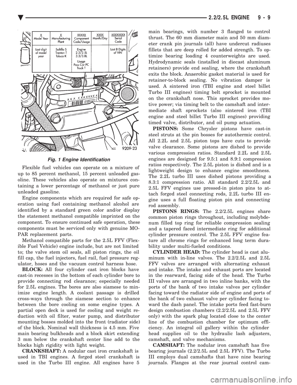
Fig. 1 Engine Identification
Ä 2.2/2.5L ENGINE 9 - 9
Page 1580 of 2438
CAUTION: Make sure clutch cable has been discon-
nected. (20) Remove front engine mount screw and nut.
(21) Remove manual transmission damper.
(22) Remove left insulator through bolt from inside
wheelhouse or insulator bracket to transmission
screws. (23) Remove engine from vehicle.
INSTALLATION
(1) Install hoist to the engine and lower engine
into the engine compartment. SEE: ENGINE MOUNT RUBBER INSULATORS,
THIS GROUP. (2) Align engine mounts and install but do not
tighten until all mounting bolts have been installed.
(3) Install transmission case to cylinder block
mounting screws. Tighten to 95 N Im (70 ft. lbs.)
torque. (4) Remove engine hoist and transmission holding
fixture. (5) Install ground strap.
(6) Install right inner splash shield.
(7) Connect starter. See Electrical Group 8 for in-
stallation. (8) Connect exhaust system. See Exhaust Systems
Group 11 for installation. (9) Manual Transmission: Install transmission
case lower cover. Automatic Transmission: Remove C clamp from
torque converter housing. Align flexplate to torque
converter and install mounting screws. Tighten to 75
N Im (55 ft. lbs.) torque.
(10) Manual Transmission: Connect clutch cable.
See Clutch Group 6. (11) Install power steering pump. Refer to Cooling
System Group 7, Accessory Drive Section for belt
tension adjustment. (12) Connect fuel line, heater hose, and accelerator
cable. (13) Connect all electrical connections and har-
nesses at throttle body and engine. (14) Install oil filter. Fill engine crankcase with
proper oil to correct level. (15) Install air conditioning compressor (if
equipped). See Heater and Air Conditioning, Group
24 for installation. (16) Install air cleaner and hoses.
(17) Install radiator and shroud assembly . Install
radiator hoses. Fill cooling system. See Cooling Sys-
tem Group 7 for filling procedure. (18) Install hood.
(19) Connect battery.
(20) Start engine and run until operating temper-
ature is reached. (21) Adjust transmission linkage, if necessary.
SOLID MOUNT COMPRESSOR BRACKET SERVICE
When service procedures require solid mount
bracket removal and installation for example: cylin-
der head removal, etc., it is important that bracket
fasteners numbered 1 through 7 (Fig. 4) be removed
and installed in sequence, as instructed in Remove
and Install.
ACCESSORIES REMOVAL
(1) Remove (and install/adjust) belts,see Accessory
Drive Belts in Cooling System,Group 7. (2) Remove air conditioning compressor (in vehicle
with lines and set aside) (Fig. 6). (3) Remove generator pivot bolt and remove gener-
ator (in vehicle: turn wiring side up and disconnect,
then rotate generator, pulley end towards engine and
remove). (4) Remove air conditioner compressor belt idler.
SOLID MOUNT BRACKETÐREMOVAL (FIG. 4)
(1) Remove right engine mount yoke screw (see
Engine Remove Fig. 3) securing engine mount sup-
port strut to engine mount bracket. (2) Remove five side mounting bolts #1, #4 , #5,
#6, and #7 (Fig. 4). (3) Remove front mounting nut, #2, and remove
front bolt #3*. (4) Remove front mounting bolt and strut, rotate
solid mount bracket away from engine and slide
bracket on stud until #2 nut mounting stud until
free. Remove spacer from stud.
SOLID MOUNT BRACKETÐINSTALLATION
(1) Put spacer onto stud, then install bracket on
front (#2 nut) mounting stud and slide bracket over
timing belt cover into position. (2) Loosen assembly bracket to engine fasteners
(numbered #1 through #7 in Fig. 6). (3)
CAUTION: Fasteners MUST BE TIGHTENED IN SE-
QUENCE and to specified torque as follows :
² First Bolt #1 to 3.3 N Im (30 in. lbs.)
² Second Nut #2 and Bolt #3 to 54 N Im (40 ft. lbs.).
² Third Bolts #1 (second tightening) #4 and #5 to
54 N Im (40 ft. lbs.).
² Fourth Bolts #6 and #7 to 54 N Im (40 ft. lbs.).
(4) Install generator and compressor. Tighten com-
pressor mounting bracket bolts to 54 N Im (40 ft.
lbs.).
SOLID MOUNT COMPRESSOR BRACKET SERVICEÐTURBO III ENGINE
REMOVAL
(1) Disconnect negative battery cable
9 - 14 2.2/2.5L ENGINE Ä
Page 1589 of 2438
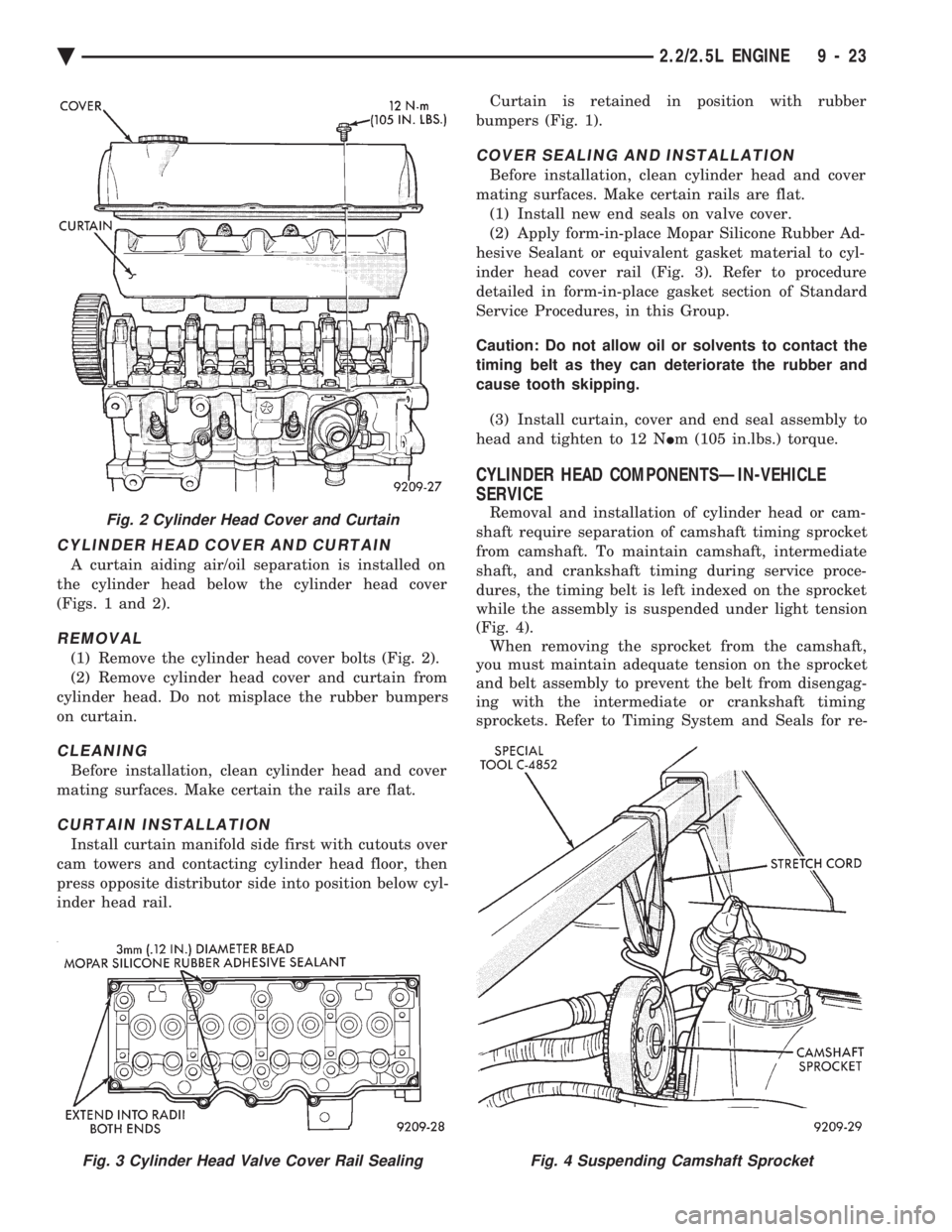
CYLINDER HEAD COVER AND CURTAIN
A curtain aiding air/oil separation is installed on
the cylinder head below the cylinder head cover
(Figs. 1 and 2).
REMOVAL
(1) Remove the cylinder head cover bolts (Fig. 2).
(2) Remove cylinder head cover and curtain from
cylinder head. Do not misplace the rubber bumpers
on curtain.
CLEANING
Before installation, clean cylinder head and cover
mating surfaces. Make certain the rails are flat.
CURTAIN INSTALLATION
Install curtain manifold side first with cutouts over
cam towers and contacting cylinder head floor, then
press opposite distributor side into position below cyl-
inder head rail. Curtain is retained in position with rubber
bumpers (Fig. 1).
COVER SEALING AND INSTALLATION
Before installation, clean cylinder head and cover
mating surfaces. Make certain rails are flat. (1) Install new end seals on valve cover.
(2) Apply form-in-place Mopar Silicone Rubber Ad-
hesive Sealant or equivalent gasket material to cyl-
inder head cover rail (Fig. 3). Refer to procedure
detailed in form-in-place gasket section of Standard
Service Procedures, in this Group.
Caution: Do not allow oil or solvents to contact the
timing belt as they can deteriorate the rubber and
cause tooth skipping.
(3) Install curtain, cover and end seal assembly to
head and tighten to 12 N Im (105 in.lbs.) torque.
CYLINDER HEAD COMPONENTSÐIN-VEHICLE
SERVICE
Removal and installation of cylinder head or cam-
shaft require separation of camshaft timing sprocket
from camshaft. To maintain camshaft, intermediate
shaft, and crankshaft timing during service proce-
dures, the timing belt is left indexed on the sprocket
while the assembly is suspended under light tension
(Fig. 4). When removing the sprocket from the camshaft,
you must maintain adequate tension on the sprocket
and belt assembly to prevent the belt from disengag-
ing with the intermediate or crankshaft timing
sprockets. Refer to Timing System and Seals for re-Fig. 2 Cylinder Head Cover and Curtain
Fig. 3 Cylinder Head Valve Cover Rail SealingFig. 4 Suspending Camshaft Sprocket
Ä 2.2/2.5L ENGINE 9 - 23