1993 CHEVROLET PLYMOUTH ACCLAIM tow
[x] Cancel search: towPage 478 of 2438

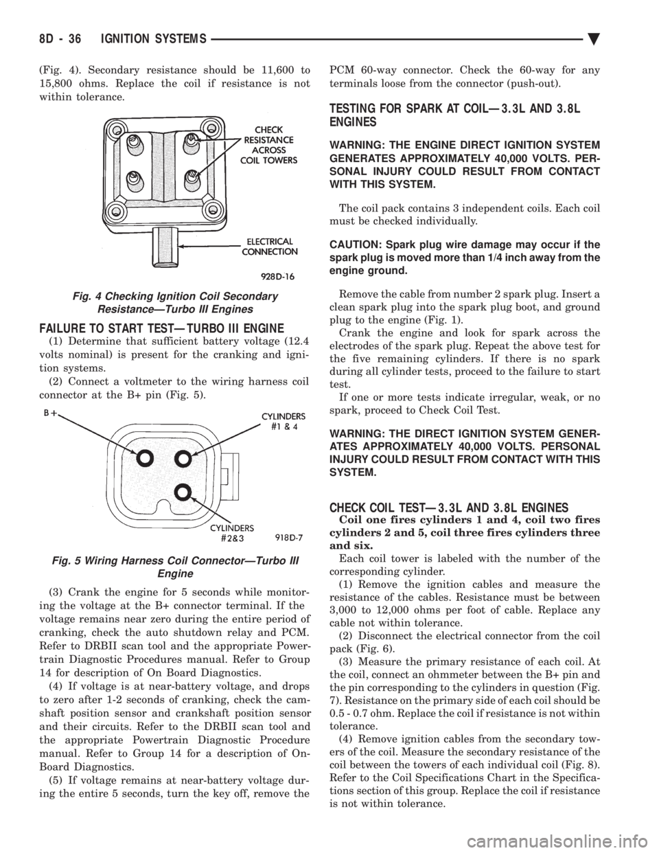
(Fig. 4). Secondary resistance should be 11,600 to
15,800 ohms. Replace the coil if resistance is not
within tolerance.
FAILURE TO START TESTÐTURBO III ENGINE
(1) Determine that sufficient battery voltage (12.4
volts nominal) is present for the cranking and igni-
tion systems. (2) Connect a voltmeter to the wiring harness coil
connector at the B+ pin (Fig. 5).
(3) Crank the engine for 5 seconds while monitor-
ing the voltage at the B+ connector terminal. If the
voltage remains near zero during the entire period of
cranking, check the auto shutdown relay and PCM.
Refer to DRBII scan tool and the appropriate Power-
train Diagnostic Procedures manual. Refer to Group
14 for description of On Board Diagnostics. (4) If voltage is at near-battery voltage, and drops
to zero after 1-2 seconds of cranking, check the cam-
shaft position sensor and crankshaft position sensor
and their circuits. Refer to the DRBII scan tool and
the appropriate Powertrain Diagnostic Procedure
manual. Refer to Group 14 for a description of On-
Board Diagnostics. (5) If voltage remains at near-battery voltage dur-
ing the entire 5 seconds, turn the key off, remove the PCM 60-way connector. Check the 60-way for any
terminals loose from the connector (push-out).
TESTING FOR SPARK AT COILÐ3.3L AND 3.8L
ENGINES
WARNING: THE ENGINE DIRECT IGNITION SYSTEM
GENERATES APPROXIMATELY 40,000 VOLTS. PER-
SONAL INJURY COULD RESULT FROM CONTACT
WITH THIS SYSTEM.
The coil pack contains 3 independent coils. Each coil
must be checked individually.
CAUTION: Spark plug wire damage may occur if the
spark plug is moved more than 1/4 inch away from the
engine ground.
Remove the cable from number 2 spark plug. Insert a
clean spark plug into the spark plug boot, and ground
plug to the engine (Fig. 1). Crank the engine and look for spark across the
electrodes of the spark plug. Repeat the above test for
the five remaining cylinders. If there is no spark
during all cylinder tests, proceed to the failure to start
test. If one or more tests indicate irregular, weak, or no
spark, proceed to Check Coil Test.
WARNING: THE DIRECT IGNITION SYSTEM GENER-
ATES APPROXIMATELY 40,000 VOLTS. PERSONAL
INJURY COULD RESULT FROM CONTACT WITH THIS
SYSTEM.
CHECK COIL TESTÐ3.3L AND 3.8L ENGINES
Coil one fires cylinders 1 and 4, coil two fires
cylinders 2 and 5, coil three fires cylinders three
and six. Each coil tower is labeled with the number of the
corresponding cylinder. (1) Remove the ignition cables and measure the
resistance of the cables. Resistance must be between
3,000 to 12,000 ohms per foot of cable. Replace any
cable not within tolerance. (2) Disconnect the electrical connector from the coil
pack (Fig. 6). (3) Measure the primary resistance of each coil. At
the coil, connect an ohmmeter between the B+ pin and
the pin corresponding to the cylinders in question (Fig.
7). Resistance on the primary side of each coil should be
0.5 - 0.7 ohm. Replace the coil if resistance is not within
tolerance. (4) Remove ignition cables from the secondary tow-
ers of the coil. Measure the secondary resistance of the
coil between the towers of each individual coil (Fig. 8).
Refer to the Coil Specifications Chart in the Specifica-
tions section of this group. Replace the coil if resistance
is not within tolerance.
Fig. 4 Checking Ignition Coil Secondary ResistanceÐTurbo III Engines
Fig. 5 Wiring Harness Coil ConnectorÐTurbo III Engine
8D - 36 IGNITION SYSTEMS Ä
Page 483 of 2438

(2) With engine running, move test probe along
entire length of all cables (approximately 0 to 1/8
inch gap). If punctures or cracks are present there
will be a noticeable spark jump from the faulty area
to the probe. Cracked, leaking or faulty cables should
be replaced. Use the following procedure when removing the
high tension cable from the spark plug. First, remove
the cable from the retaining bracket. Then grasp the
terminal as close as possible to the spark plug. Ro-
tate the cover (boot) slightly and pull straight back.
Do not use pliers and do not pull the cable at an
angle. Doing so will damage the insulation, cable
terminal or the spark plug insulator. Wipe spark
plug insulator clean before reinstalling cable
and cover. Resistance cables are identified by the words Elec-
tronic Suppression .
Use an ohmmeter to check cables for opens, loose
terminals or high resistance. (a) Remove cable from spark plug.
(b) Remove cable from the coil tower.
(c) Connect the ohmmeter between spark plug
end terminal and the coil end terminal. Resistance
should be within tolerance shown in the cable re-
sistance chart. If resistance is not within tolerance,
replace cable assembly. Test all spark plug cables
in same manner.
SPARK PLUG SERVICE
When replacing the spark plug cables, route the ca-
bles correctly and secure them in the appropriate re-
tainers. Incorrectly routed cables can cause the radio
to reproduce ignition noise. It can also cause cross ig-
nition of the spark plugs or short circuit the cables to
ground.
SPARK PLUG REMOVAL
Always remove cables by grasping at boot, rotating
the boot 1/2 turn, and pulling straight back in a
steady motion. (1) Prior to removing the spark plug spray com-
pressed air around the spark plug hole and the area
around the spark plug. (2) Remove the spark plug using a quality socket
with a rubber or foam insert. (3) Inspect the spark plug condition. Refer to
Spark Plug Condition in this section.
SPARK PLUG GAP ADJUSTMENT
Check the spark plug gap with a gap gauge. If the
gap is not correct, adjust it by bending the ground
electrode (Fig. 6).
SPARK PLUG INSTALLATION
(1) To avoid cross threading, start the spark plug
into the cylinder head by hand. (2) Tighten spark plugs to 28 N Im (20 ft. lbs.)
torque. (3) Install spark plug cables over spark plugs.
IDLE RPM TEST
WARNING: BE SURE TO APPLY PARKING BRAKE
AND/OR BLOCK WHEELS BEFORE PERFORMING
ANY ENGINE RUNNING TESTS.
Engine idle set rpmshould be tested and recorded
as it is when the vehicle is first brought into shop
for testing. This will assist in diagnosing complaints
of engine stalling, creeping and hard shifting on ve-
hicles equipped with automatic transaxle. Refer to the
Throttle Body Minimum Airflow procedures in Group
14.
IGNITION TIMING PROCEDURE
Ignition timing cannot be changed or set on Turbo
III, 3.3L or 3.8L engines. For diagnostic information,
refer to the DRBII scan tool and the appropriate
Powertrain Diagnostics Procedures manual.
CABLE RESISTANCE CHART
Fig. 6 Setting Spark Plug GapÐTypical
Ä IGNITION SYSTEMS 8D - 41
Page 488 of 2438

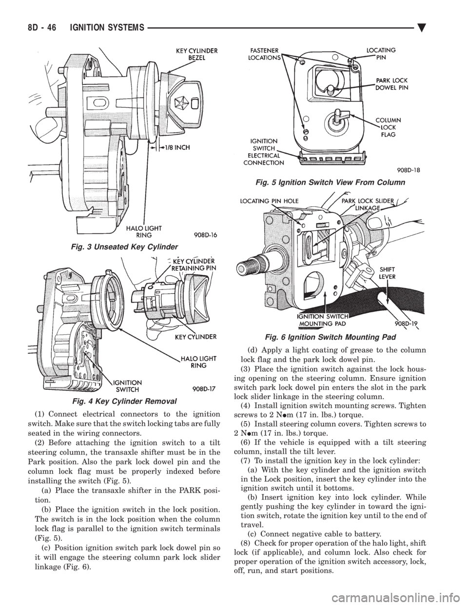
(1) Connect electrical connectors to the ignition
switch. Make sure that the switch locking tabs are fully
seated in the wiring connectors. (2) Before attaching the ignition switch to a tilt
steering column, the transaxle shifter must be in the
Park position. Also the park lock dowel pin and the
column lock flag must be properly indexed before
installing the switch (Fig. 5). (a) Place the transaxle shifter in the PARK posi-
tion. (b) Place the ignition switch in the lock position.
The switch is in the lock position when the column
lock flag is parallel to the ignition switch terminals
(Fig. 5). (c) Position ignition switch park lock dowel pin so
it will engage the steering column park lock slider
linkage (Fig. 6). (d) Apply a light coating of grease to the column
lock flag and the park lock dowel pin.
(3) Place the ignition switch against the lock hous-
ing opening on the steering column. Ensure ignition
switch park lock dowel pin enters the slot in the park
lock slider linkage in the steering column. (4) Install ignition switch mounting screws. Tighten
screws to 2 N Im (17 in. lbs.) torque.
(5) Install steering column covers. Tighten screws to
2N Im (17 in. lbs.) torque.
(6) If the vehicle is equipped with a tilt steering
column, install the tilt lever. (7) To install the ignition key in the lock cylinder:(a) With the key cylinder and the ignition switch
in the Lock position, insert the key cylinder into the
ignition switch until it bottoms. (b) Insert ignition key into lock cylinder. While
gently pushing the key cylinder in toward the igni-
tion switch, rotate the ignition key until to the end of
travel. (c) Connect negative cable to battery.
(8) Check for proper operation of the halo light, shift
lock (if applicable), and column lock. Also check for
proper operation of the ignition switch accessory, lock,
off, run, and start positions.
Fig. 3 Unseated Key Cylinder
Fig. 4 Key Cylinder Removal
Fig. 5 Ignition Switch View From Column
Fig. 6 Ignition Switch Mounting Pad
8D - 46 IGNITION SYSTEMS Ä
Page 584 of 2438

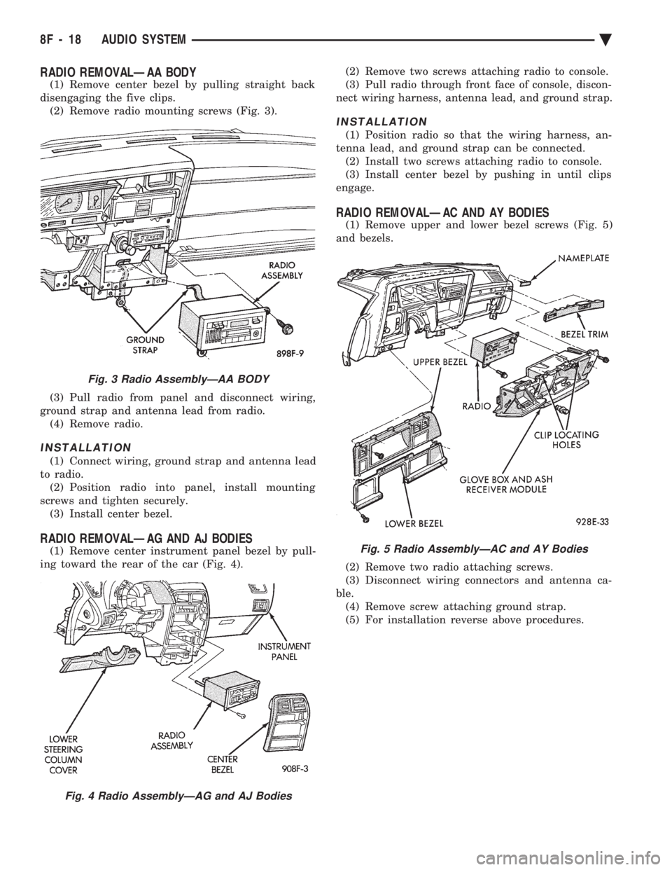
RADIO REMOVALÐAA BODY
(1) Remove center bezel by pulling straight back
disengaging the five clips. (2) Remove radio mounting screws (Fig. 3).
(3) Pull radio from panel and disconnect wiring,
ground strap and antenna lead from radio. (4) Remove radio.
INSTALLATION
(1) Connect wiring, ground strap and antenna lead
to radio. (2) Position radio into panel, install mounting
screws and tighten securely. (3) Install center bezel.
RADIO REMOVALÐAG AND AJ BODIES
(1) Remove center instrument panel bezel by pull-
ing toward the rear of the car (Fig. 4). (2) Remove two screws attaching radio to console.
(3) Pull radio through front face of console, discon-
nect wiring harness, antenna lead, and ground strap.
INSTALLATION
(1) Position radio so that the wiring harness, an-
tenna lead, and ground strap can be connected. (2) Install two screws attaching radio to console.
(3) Install center bezel by pushing in until clips
engage.
RADIO REMOVALÐAC AND AY BODIES
(1) Remove upper and lower bezel screws (Fig. 5)
and bezels.
(2) Remove two radio attaching screws.
(3) Disconnect wiring connectors and antenna ca-
ble. (4) Remove screw attaching ground strap.
(5) For installation reverse above procedures.
Fig. 3 Radio AssemblyÐAA BODY
Fig. 4 Radio AssemblyÐAG and AJ Bodies
Fig. 5 Radio AssemblyÐAC and AY Bodies
8F - 18 AUDIO SYSTEM Ä
Page 589 of 2438

(8) Upon establishing that the fault is in the an-
tenna assembly, it may be traced to one or more of
the following conditions: (a) Broken lead-in wire or shielding.
(b) Grounded lead-in wire or mast assembly.
(c) Moisture in support tube or lead-in assembly.
(d) Poor connection at antenna lead-in assembly
or shielding ground.
REMOVAL
(1) Disconnect battery negative cable.
(2) Remove the right front fender splash shield fas-
teners and pull shield away from the wheel housing.
(3) Disconnect motor leads at the connector (Fig. 15).
(4) Disconnect lead-in cable by twisting at connec-
tor (Fig. 17).
(5) Remove one screw attaching antenna to an-
tenna brace (Fig. 18). (6) Remove cap nut on fender surface with An-
tenna Nut Wench C-4816 (Fig. 11). (7) Remove antenna from under fender.
INSTALLATION
(1) Position antenna under fender and through
fender adapter. (2) Replace and tighten cap nut to 14 N Im (125 in.
lbs.) torque with Antenna Nut Wench C-4816.
(3) Position antenna on antenna brace and install at-
taching screw. Tighten to 4 N Im (40 in. lbs.) torque.
(4) Connect antenna lead at twist connector.
(5) Connect motor leads at connector.
(6) Position right front fender splash shield and in-
stall attaching fasteners. (7) Connect negative battery cable and test opera-
tion of antenna.
POWER ANTENNA MAST
REMOVAL
(1) Remove cap nut using Antenna Nut Wrench
C-4816. (2) Install temporary nut provided with the re-
placement mast. (3) Turn ignition key to ACCESSORY position and
turn on radio. (4) While the mast is moving up pull upward to re-
move mast and drive rod from the mast tube.
INSTALLATION
(1) Insert new drive rod into mast tube with drive
teeth toward antenna motor (Fig. 19).
(2) Turn off radio and guide mast into tube. The
mast may not be fully lowered when first installed. (3) Replace the temporary nut with the original
cap nut and tighten to 14 N Im (125 in. lbs.) torque
using Antenna Nut Wench C-4816. (4) Turn radio on and off to extend and retract an-
tenna. Mast should be fully lowered after recycling.
Fig. 18 Power Antenna Mounting
Fig. 17 Power Antenna Twist Connector
Fig. 19 Power Antenna Mast
Ä AUDIO SYSTEM 8F - 23
Page 596 of 2438

COMPACT DISC PLAYER
WARNING: USE OF THE CONTROLS, ADJUST-
MENTS, OR SERVICE PROCEDURES NOT SPECI-
FIED HERE OR IN THE OWNER MANUAL MAY
RESULT IN HAZARDOUS RADIATION EXPOSURE.
REPAIR PROCEDURES SHOULD ONLY BE PER-
FORMED BY A TRAINED TECHNICIAN.
DIAGNOSIS TEST
Power to the compact disc player is supplied by the
radio through the CD interface cable. The compact
disc player will only work with the radio system
turned ON. When a compact disc is inserted with the
label side facing up, the disc is automatically loaded
and will begin to play. The CD player may eject the disc with a display of
E under the following conditions:
² The surface of the disc is dirty or wet
² The disc was inserted with the label side facing
down
² The disc is defective
² The CD player may skip or mute while playing a
disc under severe vibration conditions example pot
holes, railroad tracks, etc.
² If the CD player becomes too hot at temperatures
above 60ÉC (140 ÉF) the CD player will shut down
with a display of HOT until it cools down. Refer to
the Audio Diagnostic Charts.
COMPACT DISC PLAYER REPLACEMENT
With intergral compact disc player refer to Radio
Removal.
AJ BODY
(1) Remove center instrument panel bezel by pull-
ing toward the rear of the car. (2) Remove two screws attaching disc player to
console (Fig. 36). (3) Pull disc player out of console and disconnect
interface cable. (4) To install compact disc player, above the re-
moval procedures.
Fig. 36 Compact Disc Player
8F - 30 AUDIO SYSTEM Ä
Page 605 of 2438

INOPERATIVE SYSTEM
If road test verifies an inoperative system with a
correct speedometer operation:
² Inspect fuse
² Check for loose electrical and vacuum connections
at the servo
² Check for correct position of the vacuum check
valve in the hose from servo to vacuum source. The
word VAC on the valve must point toward the vac-
uum source.
² Inspection should also be made to verify that both
ends of the vehicle speed control cable are securely
attached. If either end is loose, the vehicle speed con-
trol will be inoperative.
CHECKING FOR FAULT CODE
(1) When trying to verify a vehicle speed control
electronic malfunction: (a) Connect a DRB II if available.
(b) Plug DRB II into the diagnostic connector in
the engine compartment. (c) Check that either a Fault Code 34 or Fault
Code 15 is indicated. (d) An inoperative vehicle speed control may still
occur without either fault code being indicated. (e) With key inserted in ignition switch, cycle
switch to ON position three times. On third cycle,
leave switch in ON position. (f) After switch has been cycled three times, ob-
serve CHECK ENGINE indicator on instrument
cluster. If a Fault Code is present, indicator will
flash (blink) in a series which will show which
Fault Code is the problem. EXAMPLE: A series of
three flashes in rapid succession, a slight pause,
then four flashes in rapid succession would indicate
Fault Code 34.
(2) If no Fault Code appears, or Fault Code 34 is
observed, refer to:
² The Servo Electrical Test.
² The Powertrain Control Module Electrical Test.
(3) If a fault code 15 is observed, test vehicle speed
sensor. For testing vehicle speed sensor and related compo-
nents refer to the Powertrain Diagnostics Test Proce-
dure Manual. (4) Correct any problems found when performing
these tests and recheck for Fault Code if changes
were made. (5) If no problems were found above, replace pow-
ertrain control module.
VEHICLE SPEED CONTROL ELECTRICAL TESTS
WARNING: IF REMOVAL OF AIR BAG MODULE IS
NECESSARY, REFER TO GROUP 8M, RESTRAINT
SYSTEMS.
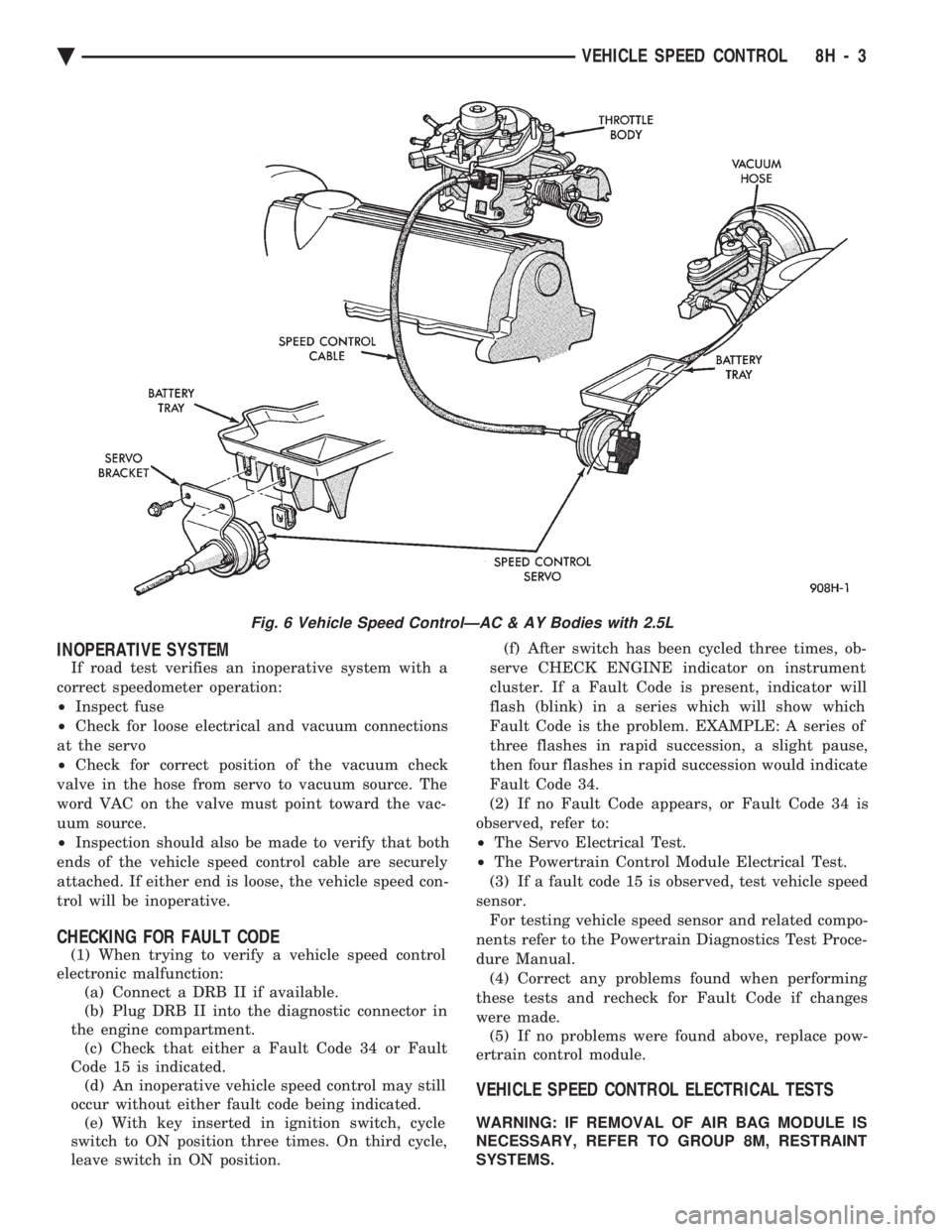
Fig. 6 Vehicle Speed ControlÐAC & AY Bodies with 2.5L
Ä VEHICLE SPEED CONTROL 8H - 3
Page 613 of 2438

TURN SIGNALS AND HAZARD WARNING FLASHER
CONTENTS
page page
AG AND AJ BODIES ..................... 1
CHIME FUNCTIONÐAC, AG, AJ AND AY .... 1
DUAL-FUNCTION SWITCHÐAG AND AJ BODIES.5
GENERAL INFORMATION .................. 1
HAZARD WARNING SYSTEM .............. 1
MULTI-FUNCTION SWITCHÐAA, AC, AP AND AY BODIES .............................. 2 REMOTE TURN SIGNAL SWITCH REMOVALÐAG
AND AJ BODIES ....................... 5
TESTING PROCEDURES ................... 2
TURN SIGNAL AND HAZARD WARNING FLASHER LOCATION ............................ 6
TURN SIGNAL RELAYSÐAG AND AJ BODIES . 6
GENERAL INFORMATION
WARNING: ON VEHICLES EQUIPPED WITH AIR-
BAG, SEE GROUP 8M, RESTRAINT SYSTEMS FOR
AIRBAG REMOVAL PROCEDURES.
TURN SIGNALSÐAC, AY, AA AND AP BODIES
The turn signals are part of the multi-function switch.
Which contains electrical circuitry for turn signal, cor-
nering lamps, hazard warning, headlamp beam select,
headlamp optical horn, windshield wiper, pulse wipe
and windshield washer switching. The integrated switch
assembly is mounted to the left hand side of the steer-
ing column. When the driver wishes to signal his inten-
tions to change direction of travel, he moves the lever
upward to cause the right signals to flash and down-
ward to cause the left signals to flash. After completion
of a turn the system is deactivated automatically. As
the steering wheel returns to the straight ahead posi-
tion, a canceling cam of two lobes molded to the clock-
spring mechanism comes in contact with the cancel
actuator on the turn signal multi-function switch as-
sembly. Either cam lobe, pushing on the cancel actua-
tor, returns the switch to the off position. If only momentary signaling such as indication of a
lane change is desired, the switch is actuated to a left
or right intermediate detent position. In this position
the signal lamps flash as described above, but the
switch returns to the OFF position as soon as the lever
is released.
When the system is activated, 1 of 2 indicator
lamps mounted in the instrument cluster flashes in
unison with the turn signal lamps, indicating to the
driver that the system is operating.
AG AND AJ BODIES
The turn signals are actuated with lever on the left
side of the instrument panel switch pod. When the
driver wishes to signal his intentions to change di- rection of travel, he moves the lever upward to cause
the right signals to flash and downward to cause the
left signals to flash. After completion of a turn the system is deacti-
vated automatically. The cancellation switch in the
steering column sends a signal to a remote turn sig-
nal switch in the switch pod to cancel the turn signal
function. As the steering wheel returns to the
straight ahead position from a turn, a cancel cam
which is located on the steering wheel contacts a
cancel flipper located on the cancellation switch.
When the flipper is contacted by the cancel cam in
the proper rotational direction, the cancel switch
sends a signal to the remote turn signal switch. If only momentary signaling such as indication of a
lane change is desired, the switch is actuated to a
left or right intermediate detent position. In this po-
sition the signal lamps flash as described above, but
the switch returns to the OFF position as soon as the
lever is released. When the system is activated, 1 of 2 indicator
lamps mounted in the instrument cluster flashes in
unison with the turn signal lamps, indicating to the
driver that the system is operating.
HAZARD WARNING SYSTEM
The hazard warning system is actuated by a push
button located on the top of the steering column be-
tween the steering wheel and the instrument panel.
The hazard switch is identified with a double trian-
gle on top of the button. Push and release the button
to turn the hazard function ON or OFF. The button
will move out from the steering column in the ON
position and will remain in toward the column in the
OFF position.
CHIME FUNCTIONÐAC, AG, AJ AND AY
The chime will sound after the vehicle has traveled
a distance of 0.6 miles at a speed above 15 miles per
hour.
Ä TURN SIGNALS AND HAZARD WARNING FLASHER 8J - 1