Page 368 of 2438
by tightening adjusting screw (Figs. 3 and 4 ).
Tighten pulley nut to 54 N Im (40 ft. lbs.) after ad-
justment.
GENERATOR/POWER STEERING PUMP BELT
The Poly-V generator/power steering pump belt is
provided with a dynamic tensioner (Fig. 5) to main-
tain proper belt tension. To remove or install this
belt, Release tension by rotating the tensioner clock-
wise
3.3/3.8L AND TURBO III ENGINE ACCESSORY
DRIVE BELT REMOVE AND INSTALL
GENERATOR, POWER STEERING PUMP, AIR
CONDITIONING COMPRESSOR AND WATER
PUMP DRIVE BELT The Poly-V Drive belt is provided with a dynamic
tensioner (Figs. 7 and 8) to maintain proper belt ten-
sion. To remove or install this belt. (1) Raise vehicle on hoist.
(2) Remove right front splash shield.
(3) Release tension by rotating the tensioner clock-
wise (Figs. 7 and 8). (4) Reverse above procedure to install.
Fig. 5 Release Belt Tensioner
Fig. 6 Belt Tension Chart
Fig. 4 Air Conditioning Belt Idler
7 - 26 COOLING SYSTEM Ä
Page 369 of 2438
Fig. 7 Accessory Drive BeltÐ2.2L Turbo III Engine
Fig. 8 Accessory Drive BeltÐ3.3/3.8L Engines
Ä COOLING SYSTEM 7 - 27
Page 370 of 2438

ENGINE BLOCK HEATER
DESCRIPTION AND OPERATION
On all models an engine block heater is available as
an optional accessory. The heater, operated by ordinary
house current (110 Volt A.C.) through a power cord and
connector behind the radiator grille, provides easier
engine starting and faster warm-up when vehicle is
operated in areas having extremely low temperatures.
The heater is mounted in a core hole (in place of a core
hole plug) in the engine block, with the heating ele-
ment immersed in coolant (Fig. 9). The power cord must be secured in its retainer
clips, and not positioned so it could contact link-
ages or exhaust manifolds and become damaged. If unit does not operate, trouble can be in either the
power cord or the heater element. Test power cord for
continuity with a 110-volt voltmeter or 110-volt test
light; test heater element continuity with an ohmmeter
or 12-volt test light.
REMOVAL
(1) Drain coolant from radiator and cylinder block.
Refer to Cooling System Drain, Clean, Flush and Re-
fill of this section for procedure. (2) Detach power cord plug from heater.
(3) Loosen screw in center of heater. Remove
heater assembly.
INSTALLATION
(1) Thoroughly clean core hole and heater seat.
(2) Insert heater assembly with element loop posi-
tioned upward.
(3) With heater seated, tighten center screw se-
curely to assure a positive seal. (4) Fill cooling system with coolant to the proper
level, vent air, and inspect for leaks. Pressurize sys-
tem with Radiator Pressure Tool before looking for
leaks.
Fig. 9 Engine Block Heater
7 - 28 COOLING SYSTEM Ä
Page 371 of 2438
SPECIFICATIONS
TORQUE
COOLING SYSTEM CAPACITY
Ä COOLING SYSTEM 7 - 29
Page 411 of 2438

GENERATOR INDEX
page page
General Information ........................ 9
Generator ReplacementÐ2.2L Turbo Engine (With 16 Valve Cylinder Head) ............. 10 Generator ReplacementÐ2.2L/2.5L Engine
...... 9
Generator ReplacementÐ3.0L Engine ......... 10
Generator ReplacementÐ3.3L/3.8L Engine ..... 11
GENERAL INFORMATION
This section will cover generator removal and instal-
lation only. Information covering generator on-vehicle
testing and diagnosis can be found in Group 8A,
Battery/Starting/Charging Systems Diagnostics. To
identify the generator, refer to the Generator Specifi-
cation chart at the rear of this section. These generators are not intended to be disas-
sembled for service. It must be replaced as an
assembly.
GENERATOR REPLACEMENTÐ2.2L/2.5L ENGINE
Removal and repositioning of A/C compressor (with-
out disconnecting refrigerant lines) is necessary on
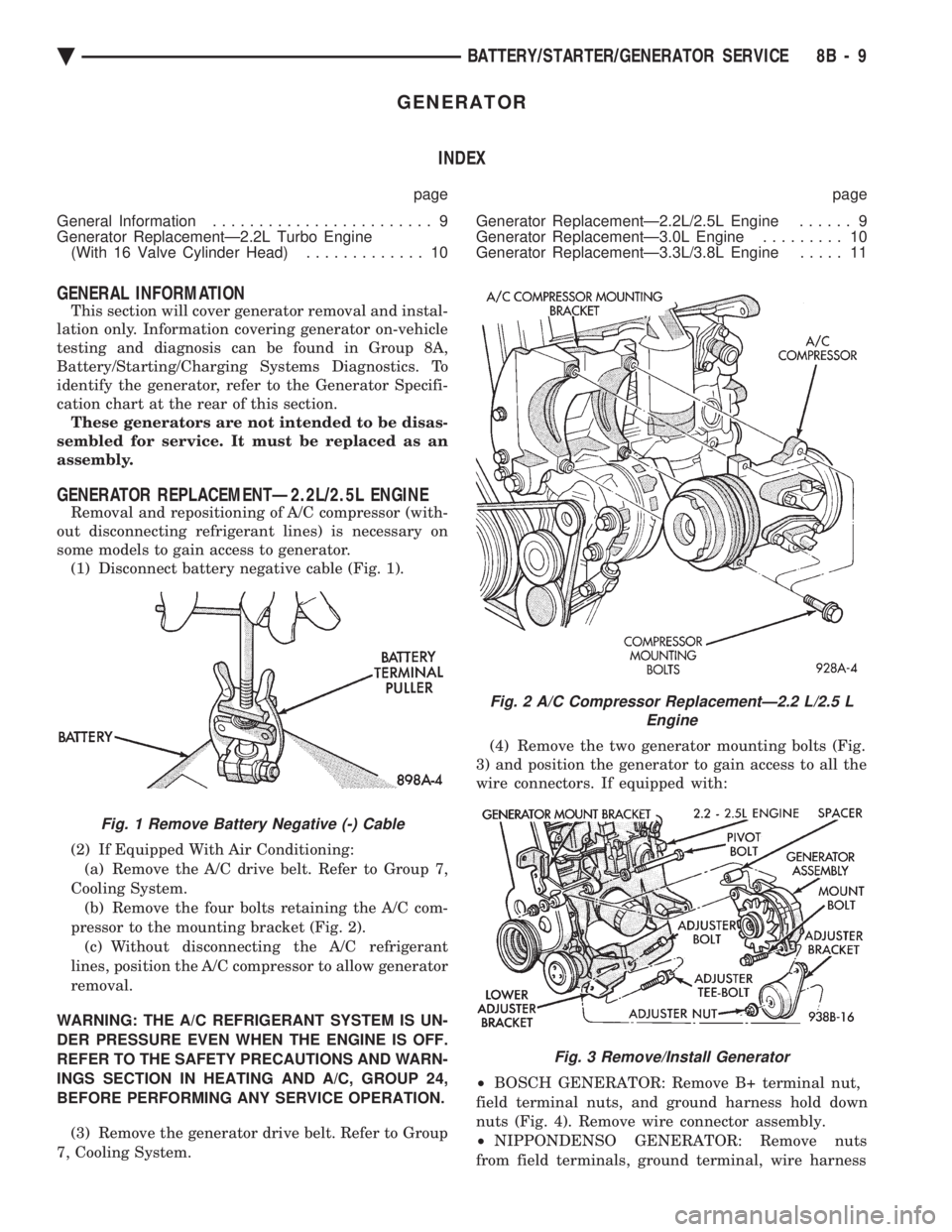
some models to gain access to generator. (1) Disconnect battery negative cable (Fig. 1).
(2) If Equipped With Air Conditioning:
(a) Remove the A/C drive belt. Refer to Group 7,
Cooling System. (b) Remove the four bolts retaining the A/C com-
pressor to the mounting bracket (Fig. 2). (c) Without disconnecting the A/C refrigerant
lines, position the A/C compressor to allow generator
removal.
WARNING: THE A/C REFRIGERANT SYSTEM IS UN-
DER PRESSURE EVEN WHEN THE ENGINE IS OFF.
REFER TO THE SAFETY PRECAUTIONS AND WARN-
INGS SECTION IN HEATING AND A/C, GROUP 24,
BEFORE PERFORMING ANY SERVICE OPERATION. (3) Remove the generator drive belt. Refer to Group
7, Cooling System. (4) Remove the two generator mounting bolts (Fig.
3) and position the generator to gain access to all the
wire connectors. If equipped with:
² BOSCH GENERATOR: Remove B+ terminal nut,
field terminal nuts, and ground harness hold down
nuts (Fig. 4). Remove wire connector assembly.
² NIPPONDENSO GENERATOR: Remove nuts
from field terminals, ground terminal, wire harness
Fig. 1 Remove Battery Negative (-) Cable
Fig. 2 A/C Compressor ReplacementÐ2.2 L/2.5 L Engine
Fig. 3 Remove/Install Generator
Ä BATTERY/STARTER/GENERATOR SERVICE 8B - 9
Page 412 of 2438

and B+ terminal (Fig. 5). B+ terminal nut must be
removed last to prevent damage to terminal insula-
tor. (5) Remove the generator from the vehicle.
(6) For installation, reverse above procedures.
Tighten all fasteners to the proper torque. Refer to
the Torque Specifications chart at the rear of this
group.
GENERATOR REPLACEMENTÐ2.2L TURBO
ENGINE (WITH 16 VALVE CYLINDER HEAD)
(1) Disconnect battery NEGATIVE cable (Fig. 1).
(2) Remove generator/air conditioning drive belt.
Refer to Group 7, Cooling System. (3) Remove the bolts retaining the A/C compressor
to the mounting bracket. (4) Without disconnecting the A/C refrigerant
lines, position the A/C compressor to allow generator
removal. WARNING: THE A/C REFRIGERANT SYSTEM IS UN-
DER PRESSURE EVEN WHEN THE ENGINE IS OFF.
REFER TO THE SAFETY PRECAUTIONS AND
WARNINGS SECTION IN HEATING AND A/C,
GROUP 24, BEFORE PERFORMING ANY SERVICE
OPERATION.
(5) Remove the generator mounting bracket bolts
and separate generator from mounting bracket (Fig.
6).
(6) Remove the B+ terminal nut, field terminal
nuts, and ground/wire harness hold-down nuts. Re-
move wire connectors. (7) Remove the generator from the vehicle.
(8) For installation, reverse above procedures.
Tighten all fasteners to the proper torque. Refer to
the Torque Specifications chart at the rear of this
group.
GENERATOR REPLACEMENTÐ3.0L ENGINE
(1) Disconnect battery negative cable (Fig. 1).
(2) Remove generator drive belt. Refer to Group 7,
Cooling System. (3) Remove the generator mounting bolts and sep-
arate the generator from the mounting bracket (Fig.
7). (4) Remove the B+ terminal nut, field terminal
nuts, and ground/wire harness hold-down nuts. Re-
move wire connectors. (5) Remove the generator from the vehicle.
Fig. 4 Remove or Install Wire Connector AssemblyÐBosch Generator
Fig. 5 Remove or Install Wire ConnectorAssemblyÐNippondenso Generator
Fig. 6 Generator MountingÐ2.2 L Turbo Engine With 16 Valve Cylinder Head
8B - 10 BATTERY/STARTER/GENERATOR SERVICE Ä
Page 413 of 2438

(6) For installation, reverse above procedure.
Tighten all fasteners to the proper torque. Refer to
the Torque Specifications chart at the rear of this
group.
GENERATOR REPLACEMENTÐ3.3L/3.8L ENGINE
(1) Disconnect battery negative cable (Fig. 1).
(2) Remove generator drive belt. Refer to Group 7,
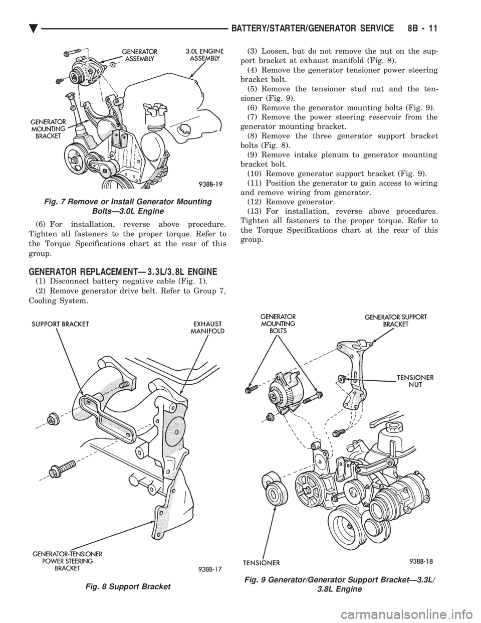
Cooling System. (3) Loosen, but do not remove the nut on the sup-
port bracket at exhaust manifold (Fig. 8). (4) Remove the generator tensioner power steering
bracket bolt. (5) Remove the tensioner stud nut and the ten-
sioner (Fig. 9). (6) Remove the generator mounting bolts (Fig. 9).
(7) Remove the power steering reservoir from the
generator mounting bracket. (8) Remove the three generator support bracket
bolts (Fig. 8). (9) Remove intake plenum to generator mounting
bracket bolt. (10) Remove generator support bracket (Fig. 9).
(11) Position the generator to gain access to wiring
and remove wiring from generator. (12) Remove generator.
(13) For installation, reverse above procedures.
Tighten all fasteners to the proper torque. Refer to
the Torque Specifications chart at the rear of this
group.
Fig. 7 Remove or Install Generator Mounting BoltsÐ3.0L Engine
Fig. 8 Support BracketFig. 9 Generator/Generator Support BracketÐ3.3L/ 3.8L Engine
Ä BATTERY/STARTER/GENERATOR SERVICE 8B - 11
Page 448 of 2438

ing, detonation and cooling system malfunctions also
can cause spark plug overheating.
SPARK PLUG SERVICE
When replacing the spark plug and coil cables,
route the cables correctly and secure them in the ap-
propriate retainers. Failure to route the cables prop-
erly can cause the radio to reproduce ignition noise,
cross ignition of the spark plugs or short circuit the
cables to ground.
SPARK PLUG REMOVAL
Always remove the spark plug cable by grasping at
the spark plug boot turning, the boot 1/2 turn and
pulling straight back in a steady motion. (1) Prior to removing the spark plug spray com-
pressed air around the spark plug hole and the area
around the spark plug. (2) Remove the spark plug using a quality socket
with a rubber or foam insert. (3) Inspect the spark plug condition. Refer to
Spark Plug Condition in this section.
SPARK PLUG GAP ADJUSTMENT Check the spark plug gap with a gap gauge. If the
gap is not correct, adjust it by bending the ground
electrode (Fig. 6).
SPARK PLUG INSTALLATION (1) To avoid cross threading, start the spark plug
into the cylinder head by hand. (2) Tighten spark plugs to 28 N Im (20 ft. lbs.)
torque. (3) Install spark plug cables over spark plugs.
POWERTRAIN CONTROL MODULE (PCM)
The ignition system is regulated by the powertrain
control module (PCM) (Fig. 14). The PCM supplies
battery voltage to the ignition coil through the Auto
Shutdown (ASD) Relay. The PCM also controls the
ground circuit for the ignition coil. By switching the ground path for the coil on and off, the PCM adjusts
ignition timing to meet changing engine operating
conditions.
During the crank-start period the PCM advances
ignition timing a set amount. During engine opera-
tion, the amount of spark advance provided by the
PCM is determined by these input factors:
² coolant temperature
² engine RPM
² available manifold vacuum
The PCM also regulates the fuel injection system.
Refer to the Fuel Injection sections of Group 14.
DISTRIBUTOR PICK-UPÐPCM INPUT
The engine speed input is supplied to the power-
train control module (PCM) by the distributor pick-
up. The distributor pick-up is a Hall Effect device
(Fig. 15 or Fig. 16).
A shutter (sometimes referred to as an interrupter)
is attached to the distributor shaft. The shutter con-
tains four blades, one per engine cylinder. A switch
plate is mounted to the distributor housing above the
shutter. The switch plate contains the distributor
Fig. 14 Powertrain control module (PCM)
Fig. 15 DistributorÐ2.2L and 2.5L TBI Engines
Fig. 13 Spark Plug Overheating
8D - 6 IGNITION SYSTEMS Ä