1993 CHEVROLET PLYMOUTH ACCLAIM cooling
[x] Cancel search: coolingPage 1580 of 2438
CAUTION: Make sure clutch cable has been discon-
nected. (20) Remove front engine mount screw and nut.
(21) Remove manual transmission damper.
(22) Remove left insulator through bolt from inside
wheelhouse or insulator bracket to transmission
screws. (23) Remove engine from vehicle.
INSTALLATION
(1) Install hoist to the engine and lower engine
into the engine compartment. SEE: ENGINE MOUNT RUBBER INSULATORS,
THIS GROUP. (2) Align engine mounts and install but do not
tighten until all mounting bolts have been installed.
(3) Install transmission case to cylinder block
mounting screws. Tighten to 95 N Im (70 ft. lbs.)
torque. (4) Remove engine hoist and transmission holding
fixture. (5) Install ground strap.
(6) Install right inner splash shield.
(7) Connect starter. See Electrical Group 8 for in-
stallation. (8) Connect exhaust system. See Exhaust Systems
Group 11 for installation. (9) Manual Transmission: Install transmission
case lower cover. Automatic Transmission: Remove C clamp from
torque converter housing. Align flexplate to torque
converter and install mounting screws. Tighten to 75
N Im (55 ft. lbs.) torque.
(10) Manual Transmission: Connect clutch cable.
See Clutch Group 6. (11) Install power steering pump. Refer to Cooling
System Group 7, Accessory Drive Section for belt
tension adjustment. (12) Connect fuel line, heater hose, and accelerator
cable. (13) Connect all electrical connections and har-
nesses at throttle body and engine. (14) Install oil filter. Fill engine crankcase with
proper oil to correct level. (15) Install air conditioning compressor (if
equipped). See Heater and Air Conditioning, Group
24 for installation. (16) Install air cleaner and hoses.
(17) Install radiator and shroud assembly . Install
radiator hoses. Fill cooling system. See Cooling Sys-
tem Group 7 for filling procedure. (18) Install hood.
(19) Connect battery.
(20) Start engine and run until operating temper-
ature is reached. (21) Adjust transmission linkage, if necessary.
SOLID MOUNT COMPRESSOR BRACKET SERVICE
When service procedures require solid mount
bracket removal and installation for example: cylin-
der head removal, etc., it is important that bracket
fasteners numbered 1 through 7 (Fig. 4) be removed
and installed in sequence, as instructed in Remove
and Install.
ACCESSORIES REMOVAL
(1) Remove (and install/adjust) belts,see Accessory
Drive Belts in Cooling System,Group 7. (2) Remove air conditioning compressor (in vehicle
with lines and set aside) (Fig. 6). (3) Remove generator pivot bolt and remove gener-
ator (in vehicle: turn wiring side up and disconnect,
then rotate generator, pulley end towards engine and
remove). (4) Remove air conditioner compressor belt idler.
SOLID MOUNT BRACKETÐREMOVAL (FIG. 4)
(1) Remove right engine mount yoke screw (see
Engine Remove Fig. 3) securing engine mount sup-
port strut to engine mount bracket. (2) Remove five side mounting bolts #1, #4 , #5,
#6, and #7 (Fig. 4). (3) Remove front mounting nut, #2, and remove
front bolt #3*. (4) Remove front mounting bolt and strut, rotate
solid mount bracket away from engine and slide
bracket on stud until #2 nut mounting stud until
free. Remove spacer from stud.
SOLID MOUNT BRACKETÐINSTALLATION
(1) Put spacer onto stud, then install bracket on
front (#2 nut) mounting stud and slide bracket over
timing belt cover into position. (2) Loosen assembly bracket to engine fasteners
(numbered #1 through #7 in Fig. 6). (3)
CAUTION: Fasteners MUST BE TIGHTENED IN SE-
QUENCE and to specified torque as follows :
² First Bolt #1 to 3.3 N Im (30 in. lbs.)
² Second Nut #2 and Bolt #3 to 54 N Im (40 ft. lbs.).
² Third Bolts #1 (second tightening) #4 and #5 to
54 N Im (40 ft. lbs.).
² Fourth Bolts #6 and #7 to 54 N Im (40 ft. lbs.).
(4) Install generator and compressor. Tighten com-
pressor mounting bracket bolts to 54 N Im (40 ft.
lbs.).
SOLID MOUNT COMPRESSOR BRACKET SERVICEÐTURBO III ENGINE
REMOVAL
(1) Disconnect negative battery cable
9 - 14 2.2/2.5L ENGINE Ä
Page 1581 of 2438
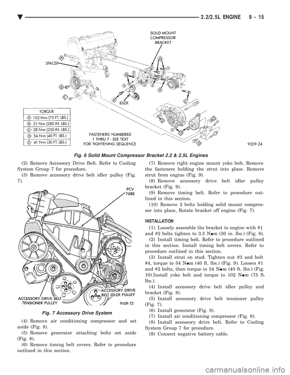
(2) Remove Accessory Drive Belt. Refer to Cooling
System Group 7 for procedure. (3) Remove accessory drive belt idler pulley (Fig.
7).
(4) Remove air conditioning compressor and set
aside (Fig. 8). (5) Remove generator attaching bolts set aside
(Fig. 8). (6) Remove timing belt covers. Refer to procedure
outlined in this section. (7) Remove right engine mount yoke bolt. Remove
the fasteners holding the strut into place. Remove
strut from engine (Fig. 9). (8) Remove accessory drive belt idler pulley
bracket (Fig. 9). (9) Remove timing belt. Refer to procedure out-
lined in this section. (10) Remove 2 bolts holding solid mount compres-
sor into place, Rotate bracket off engine (Fig. 7).
INSTALLATION
(1) Loosely assemble the bracket to engine with #1
and #2 bolts tighten to 3.3 N Im (30 in. lbs.) (Fig. 8).
(2) Install timing belt. Refer to procedure outlined
in this section. Install timing belt covers. Refer to
procedure outlined in this section. (3) Install strut on stud. Tighten nut #3 and bolt
#4, torque to 54 N Im (40 ft. lbs.) (Fig. 9). Loosen #1
and #2 bolts, then torque to 54 N Im (40 ft. lbs.) (Fig.
10).Install yoke bolt and torque to 102 N Im (75 ft.
lbs.). (4) Install accessory drive belt idler pulley and
bracket (Fig. 8). (5) Install accessory drive belt tensioner pulley
(Fig. 7). (6) Install generator (Fig. 8).
(7) Install air conditioning compressor (Fig. 8).
(8) Install accessory drive belt. Refer to Cooling
System Group 7 for procedure. (9) Connect negative battery cable.
Fig. 6 Solid Mount Compressor Bracket 2.2 & 2.5L Engines
Fig. 7 Accessory Drive System
Ä 2.2/2.5L ENGINE 9 - 15
Page 1582 of 2438
POWER STEERING/ACCESSORY DRIVE BELT TENSIONER BRACKET
REMOVAL
(1) Remove Accessory Drive Belt. Refer to Cooling
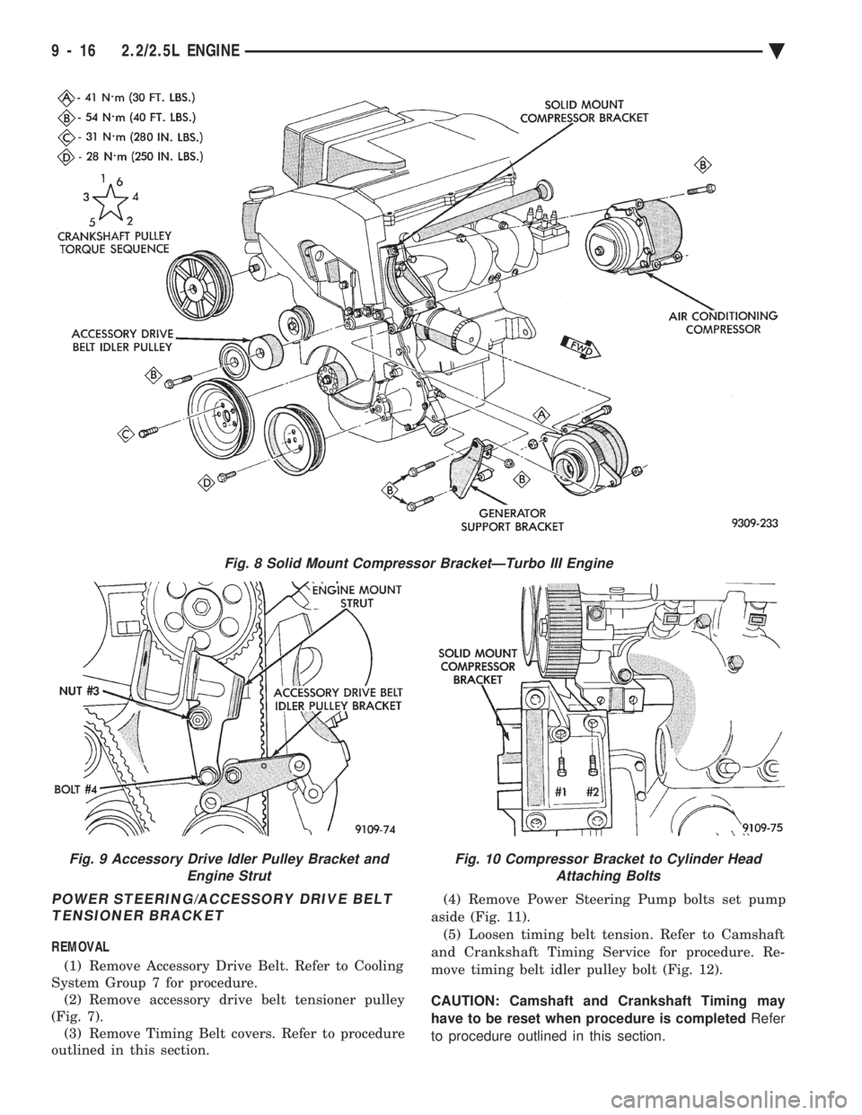
System Group 7 for procedure. (2) Remove accessory drive belt tensioner pulley
(Fig. 7). (3) Remove Timing Belt covers. Refer to procedure
outlined in this section. (4) Remove Power Steering Pump bolts set pump
aside (Fig. 11). (5) Loosen timing belt tension. Refer to Camshaft
and Crankshaft Timing Service for procedure. Re-
move timing belt idler pulley bolt (Fig. 12).
CAUTION: Camshaft and Crankshaft Timing may
have to be reset when procedure is completed Refer
to procedure outlined in this section.
Fig. 8 Solid Mount Compressor BracketÐTurbo III Engine
Fig. 9 Accessory Drive Idler Pulley Bracket and Engine StrutFig. 10 Compressor Bracket to Cylinder HeadAttaching Bolts
9 - 16 2.2/2.5L ENGINE Ä
Page 1583 of 2438
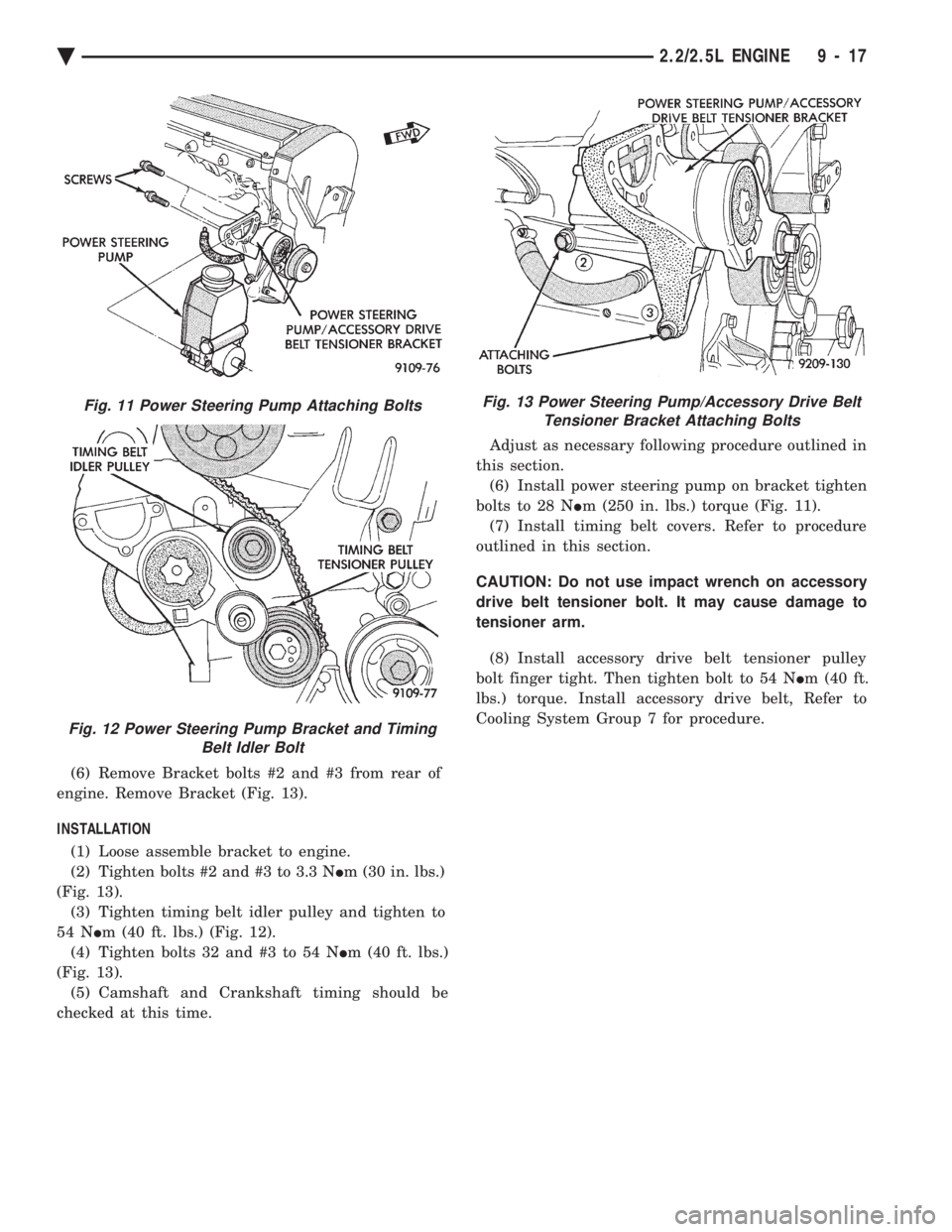
(6) Remove Bracket bolts #2 and #3 from rear of
engine. Remove Bracket (Fig. 13).
INSTALLATION (1) Loose assemble bracket to engine.
(2) Tighten bolts #2 and #3 to 3.3 N Im (30 in. lbs.)
(Fig. 13). (3) Tighten timing belt idler pulley and tighten to
54 N Im (40 ft. lbs.) (Fig. 12).
(4) Tighten bolts 32 and #3 to 54 N Im (40 ft. lbs.)
(Fig. 13). (5) Camshaft and Crankshaft timing should be
checked at this time. Adjust as necessary following procedure outlined in
this section. (6) Install power steering pump on bracket tighten
bolts to 28 N Im (250 in. lbs.) torque (Fig. 11).
(7) Install timing belt covers. Refer to procedure
outlined in this section.
CAUTION: Do not use impact wrench on accessory
drive belt tensioner bolt. It may cause damage to
tensioner arm.
(8) Install accessory drive belt tensioner pulley
bolt finger tight. Then tighten bolt to 54 N Im (40 ft.
lbs.) torque. Install accessory drive belt, Refer to
Cooling System Group 7 for procedure.
Fig. 11 Power Steering Pump Attaching Bolts
Fig. 12 Power Steering Pump Bracket and Timing Belt Idler Bolt
Fig. 13 Power Steering Pump/Accessory Drive BeltTensioner Bracket Attaching Bolts
Ä 2.2/2.5L ENGINE 9 - 17
Page 1592 of 2438
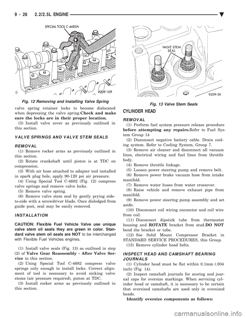
valve spring retainer locks to become dislocated
when depressing the valve spring. Check and make
sure the locks are in their proper location. (3) Install valve cover as previously outlined in
this section.
VALVE SPRINGS AND VALVE STEM SEALS
REMOVAL
(1) Remove rocker arms as previously outlined in
this section. (2) Rotate crankshaft until piston is at TDC on
compression. (3) With air hose attached to adapter tool installed
in spark plug hole, apply 90-120 psi air pressure. (4) Using Special Tool C-4682 (Fig. 12) compress
valve springs and remove valve locks. (5) Remove valve spring.
(6) Remove valve stem seal by gently prying side-
to-side with a screwdriver blade. Once dislodged from
guide post, seal may be easily removed.
INSTALLATION
CAUTION: Flexible Fuel Vehicle Valve use unique
valve stem oil seals they are green in color. Stan-
dard valve stem oil seals are NOT to be interchanged
with Flexible Fuel Vehicles engines.
(1) Install valve seals (Fig. 13) as outlined in step
(2) of Valve Gear Reassembly - After Valve Ser-
vice in this section.
(2) Using Special Tool C-4682 compress valve
springs only enough to install locks. Correct align-
ment of tool is necessary to avoid nicking valve
stems (air pressure required), piston at TDC. (3) Install rocker arms as previously outlined in
this section.
CYLINDER HEAD
REMOVAL
(1) Perform fuel system pressure release procedure
before attempting any repairs. Refer to Fuel Sys-
tem Group 14 (2) Disconnect negative battery cable. Drain cool-
ing system. Refer to Cooling System, Group 7. (3) Remove air cleaner and disconnect all vacuum
lines, electrical wiring and fuel lines from throttle
body. (4) Remove throttle linkage.
(5) Loosen power steering pump and remove belt.
(6) Remove power brake vacuum hose from intake
manifold. (7) Remove water hoses from water crossover.
(8) Raise vehicle and remove exhaust pipe from
manifold. (9) Remove power steering pump assembly and set
aside. (10) Disconnect coil wiring connector and coil wire
from coil. (11) Disconnect dipstick tube from thermostat
housing and ROTATEbracket from stud. DO NOT
bend the bracket or tube. (12) See Solid Mount Compressor Bracket in
STANDARD SERVICE PROCEDURES, this Group. (13) Remove cylinder head bolts.
INSPECT HEAD AND CAMSHAFT BEARINGJOURNALS
(1) Cylinder head must be flat within 0.1mm (.004
inch) (Fig. 14). (2) Inspect camshaft journals for scoring and jour-
nal caps for oversize markings. When servicing cyl-
inder head or camshaft, it is necessary to be certain
that oversized camshafts are used only in oversized
heads. Identify oversize components as follows:
Fig. 12 Removing and Installing Valve SpringFig. 13 Valve Stem Seals
9 - 26 2.2/2.5L ENGINE Ä
Page 1598 of 2438
Before installing the bolts, the threads should be
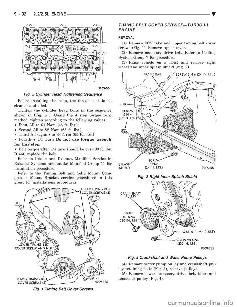
cleaned and oiled. Tighten the cylinder head bolts in the sequence
shown in (Fig. 5 ). Using the 4 step torque turn
method, tighten according to the following values:
² First All to 61 N Im (45 ft. lbs.)
² Second All to 88 N Im (65 ft. lbs.)
² Third All (again) to 88 N Im (65 ft., lbs.)
² Fourth + 1/4 Turn Do not use torque wrench
for this step.
² Bolt torque after 1/4 turn should be over 90 ft. lbs.
If not, replace the bolt. Refer to Intake and Exhaust Manifold Service in
Exhaust Systems and Intake Manifold Group 11 for
installation procedure. Refer to the Timing Belt and Solid Mount Com-
pressor Mount Bracket service procedures in this
group for installations procedures.
TIMING BELT COVER SERVICEÐTURBO III
ENGINE
REMOVAL
(1) Remove PCV tube and upper timing belt cover
screws (Fig. 1). Remove upper cover. (2) Remove accessory drive belt. Refer to Cooling
System Group 7 for procedure. (3) Raise vehicle on a hoist and remove right
wheel and inner splash shield (Fig. 2).
(4) Remove water pump pulley and crankshaft pul-
ley retaining bolts (Fig. 3), remove pulleys. (5) Remove lower accessory drive belt idler and
tensioner pulley (Fig. 4).
Fig. 1 Timing Belt Cover Screws
Fig. 5 Cylinder Head Tightening Sequence
Fig. 2 Right Inner Splash Shield
Fig. 3 Crankshaft and Water Pump Pulleys
9 - 32 2.2/2.5L ENGINE Ä
Page 1599 of 2438
CAUTION: Do not use a impact wrench to remove
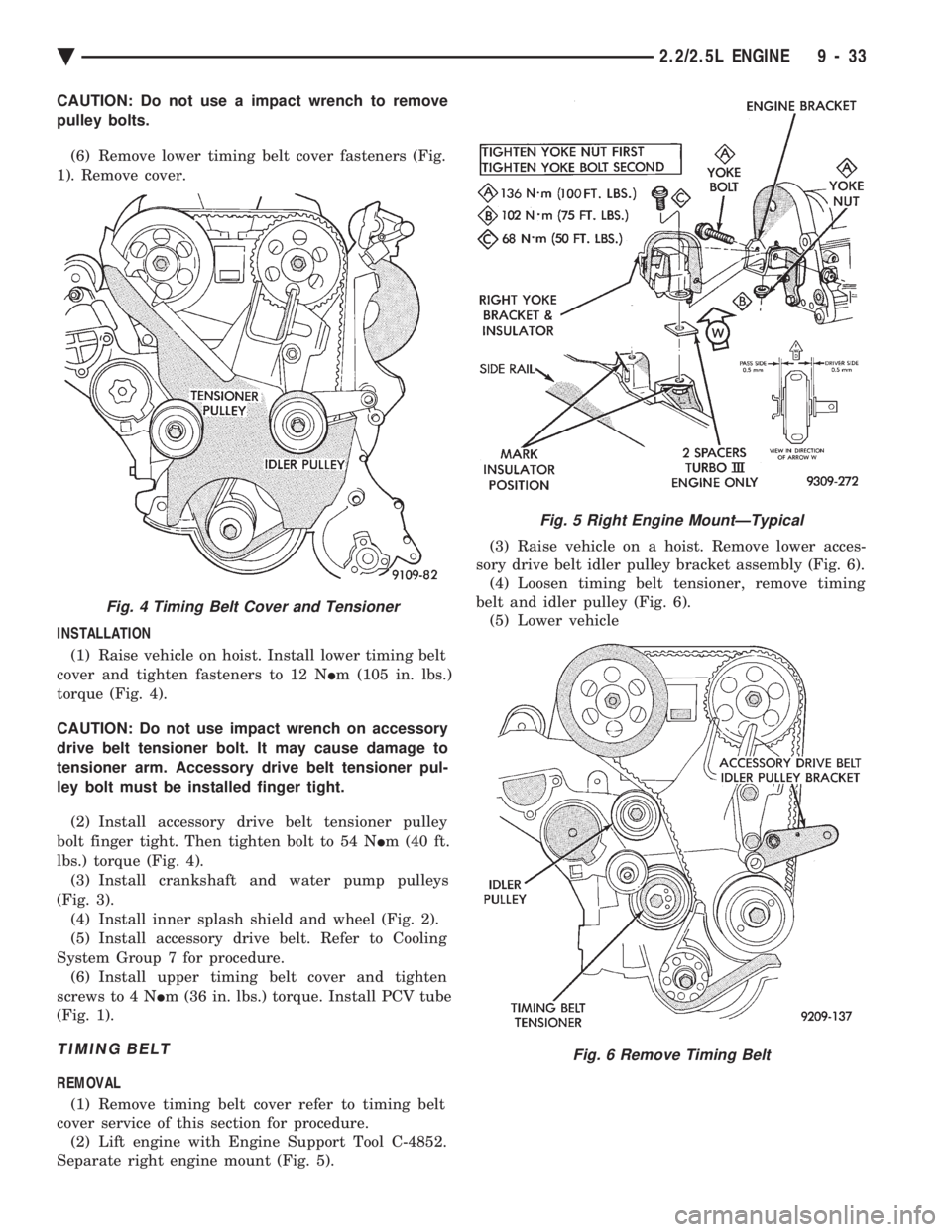
pulley bolts. (6) Remove lower timing belt cover fasteners (Fig.
1). Remove cover.
INSTALLATION (1) Raise vehicle on hoist. Install lower timing belt
cover and tighten fasteners to 12 N Im (105 in. lbs.)
torque (Fig. 4).
CAUTION: Do not use impact wrench on accessory
drive belt tensioner bolt. It may cause damage to
tensioner arm. Accessory drive belt tensioner pul-
ley bolt must be installed finger tight. (2) Install accessory drive belt tensioner pulley
bolt finger tight. Then tighten bolt to 54 N Im (40 ft.
lbs.) torque (Fig. 4). (3) Install crankshaft and water pump pulleys
(Fig. 3). (4) Install inner splash shield and wheel (Fig. 2).
(5) Install accessory drive belt. Refer to Cooling
System Group 7 for procedure. (6) Install upper timing belt cover and tighten
screws to 4 N Im (36 in. lbs.) torque. Install PCV tube
(Fig. 1).
TIMING BELT
REMOVAL
(1) Remove timing belt cover refer to timing belt
cover service of this section for procedure. (2) Lift engine with Engine Support Tool C-4852.
Separate right engine mount (Fig. 5). (3) Raise vehicle on a hoist. Remove lower acces-
sory drive belt idler pulley bracket assembly (Fig. 6). (4) Loosen timing belt tensioner, remove timing
belt and idler pulley (Fig. 6). (5) Lower vehicle
Fig. 4 Timing Belt Cover and Tensioner
Fig. 5 Right Engine MountÐTypical
Fig. 6 Remove Timing Belt
Ä 2.2/2.5L ENGINE 9 - 33
Page 1621 of 2438
CONNECTING RODS
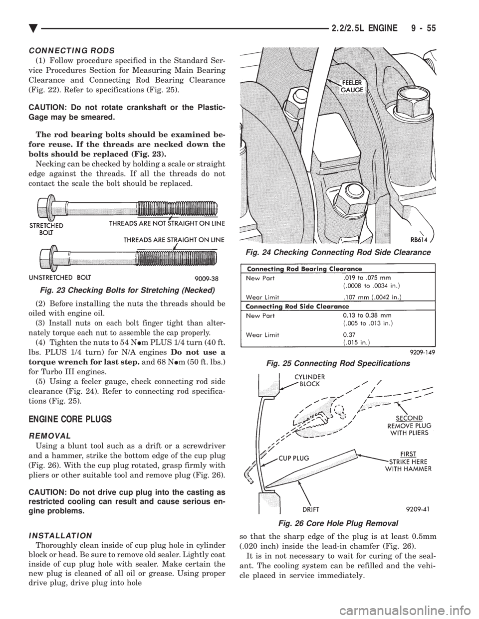
(1) Follow procedure specified in the Standard Ser-
vice Procedures Section for Measuring Main Bearing
Clearance and Connecting Rod Bearing Clearance
(Fig. 22). Refer to specifications (Fig. 25).
CAUTION: Do not rotate crankshaft or the Plastic-
Gage may be smeared.
The rod bearing bolts should be examined be-
fore reuse. If the threads are necked down the
bolts should be replaced (Fig. 23). Necking can be checked by holding a scale or straight
edge against the threads. If all the threads do not
contact the scale the bolt should be replaced.
(2) Before installing the nuts the threads should be
oiled with engine oil.
(3) Install nuts on each bolt finger tight than alter-
nately torque each nut to assemble the cap properly.
(4) Tighten the nuts to 54 N Im PLUS 1/4 turn (40 ft.
lbs. PLUS 1/4 turn) for N/A engines Do not use a
torque wrench for last step. and 68 NIm (50 ft. lbs.)
for Turbo III engines. (5) Using a feeler gauge, check connecting rod side
clearance (Fig. 24). Refer to connecting rod specifica-
tions (Fig. 25).
ENGINE CORE PLUGS
REMOVAL
Using a blunt tool such as a drift or a screwdriver
and a hammer, strike the bottom edge of the cup plug
(Fig. 26). With the cup plug rotated, grasp firmly with
pliers or other suitable tool and remove plug (Fig. 26).
CAUTION: Do not drive cup plug into the casting as
restricted cooling can result and cause serious en-
gine problems.
INSTALLATION
Thoroughly clean inside of cup plug hole in cylinder
block or head. Be sure to remove old sealer. Lightly coat
inside of cup plug hole with sealer. Make certain the
new plug is cleaned of all oil or grease. Using proper
drive plug, drive plug into hole so that the sharp edge of the plug is at least 0.5mm
(.020 inch) inside the lead-in chamfer (Fig. 26).
It is in not necessary to wait for curing of the seal-
ant. The cooling system can be refilled and the vehi-
cle placed in service immediately.
Fig. 24 Checking Connecting Rod Side Clearance
Fig. 25 Connecting Rod Specifications
Fig. 26 Core Hole Plug Removal
Fig. 23 Checking Bolts for Stretching (Necked)
Ä 2.2/2.5L ENGINE 9 - 55