Page 2242 of 2438

AJ/27-VEHICLE CONVERTIBLE BODY COMPONENT SERVICE INDEX
page page
Adjustment Procedures .................... 92
Folding Top Cover ....................... 90
Folding Top Headlining .................... 87
Folding Top Storage Sling Well .............. 87
Hydraulic Cylinder ........................ 95
Hydraulic Cylinder Line Seals ............... 95
Hydraulic Pump Assembly .................. 95
Hydraulic Pump Line Seals ................. 95 Hydraulic System Tests
.................... 95
Hydraulic Systems ........................ 95
Quarter Window ......................... 87
Rear Seat Back .......................... 86
Rear Seat Belt Retractors .................. 86
Rear Seat Cushion ....................... 86
Rear Window and Zipper ................... 88
Rear WindowÐWithout Zipper ............... 88
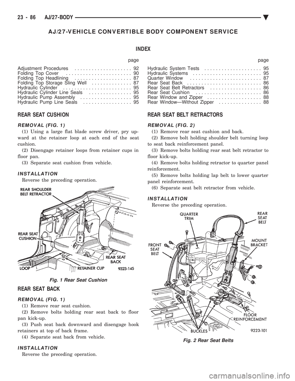
REAR SEAT CUSHION
REMOVAL (FIG. 1)
(1) Using a large flat blade screw driver, pry up-
ward at the retainer loop at each end of the seat
cushion. (2) Disengage retainer loops from retainer cups in
floor pan. (3) Separate seat cushion from vehicle.
INSTALLATION
Reverse the preceding operation.
REAR SEAT BACK
REMOVAL (FIG. 1)
(1) Remove rear seat cushion.
(2) Remove bolts holding rear seat back to floor
pan kick-up. (3) Push seat back downward and disengage hook
retainers at top of back frame. (4) Separate seat back from vehicle.
INSTALLATION
Reverse the preceding operation.
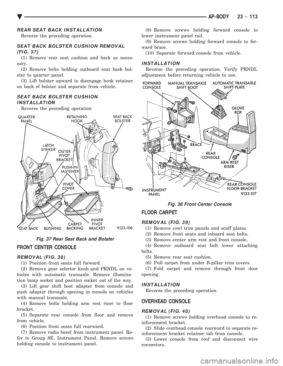
REAR SEAT BELT RETRACTORS
REMOVAL (FIG. 2)
(1) Remove rear seat cushion and back.
(2) Remove bolt holding shoulder belt turning loop
to seat back reinforcement panel. (3) Remove bolts holding rear seat belt retractor to
floor kick-up. (4) Remove bolts holding retractor to quarter panel
reinforcement. (5) Remove bolts holding lap belt to lower quarter
panel reinforcement. (6) Separate seat belt retractor from vehicle.
INSTALLATION
Reverse the preceding operation.
Fig. 1 Rear Seat Cushion
Fig. 2 Rear Seat Belts
23 - 86 AJ/27-BODY Ä
Page 2269 of 2438

REAR SEAT BACK INSTALLATION
Reverse the preceding operation.
SEAT BACK BOLSTER CUSHION REMOVAL (FIG. 37)
(1) Remove rear seat cushion and back as neces-
sary. (2) Remove bolts holding outboard seat back bol-
ster to quarter panel. (3) Lift bolster upward to disengage hook retainer
on back of bolster and separate from vehicle.
SEAT BACK BOLSTER CUSHION INSTALLATION
Reverse the preceding operation
FRONT CENTER CONSOLE
REMOVAL (FIG. 38)
(1) Position front seats full forward.
(2) Remove gear selector knob and PRNDL on ve-
hicles with automatic transaxle. Remove illumina-
tion lamp socket and position socket out of the way. (3) Lift gear shift boot adapter from console and
push adapter through opening in console on vehicles
with manual transaxle. (4) Remove bolts holding arm rest riser to floor
bracket. (5) Separate rear console from floor and remove
from vehicle. (6) Position front seats full rearward.
(7) Remove radio bezel from instrument panel. Re-
fer to Group 8E, Instrument Panel. Remove screws
holding console to instrument panel. (8) Remove screws holding forward console to
lower instrument panel rail. (9) Remove screws holding forward console to for-
ward brace. (10) Separate forward console from vehicle.
INSTALLATION
Reverse the preceding operation. Verify PRNDL
adjustment before returning vehicle to use.
FLOOR CARPET
REMOVAL (FIG. 39)
(1) Remove cowl trim panels and scuff plates.
(2) Remove front seats and inboard seat belts.
(3) Remove center arm rest and front console.
(4) Remove outboard seat belt lower attaching
bolts. (5) Remove rear seat cushion.
(6) Pull carpet from under B-pillar trim covers.
(7) Fold carpet and remove through front door
opening.
INSTALLATION
Reverse the preceding operation.
OVERHEAD CONSOLE
REMOVAL (FIG. 40)
(1) Remove screws holding overhead console to re-
inforcement bracket. (2) Slide overhead console rearward to separate re-
inforcement bracket retainer tab from console. (3) Lower console from roof and disconnect wire
connectors.
Fig. 37 Rear Seat Back and Bolster
Fig. 38 Front Center Console
Ä AP-BODY 23 - 113
Page 2273 of 2438

AP/27-VEHICLE CONVERTIBLE BODY COMPONENT SERVICE INDEX
page page
A-Pillar and Windshield Header Weatherstrip . . . 117
Convertible Top Adjustments ............... 131
Convertible Top Header ................... 118
Convertible Top Latch Hooks ............... 131
Door Glass Alignment .................... 131
Door Glass Rear Channel ................. 127
Door Striker Guide ...................... 128
Forward Roof Rail ....................... 121
Fourth Roof Bow and Slat ................. 120
Fourth Roof Bow Slat .................... 132
Front Door Belt Moulding and Weatherstrip .... 127
Front Door Glass ........................ 125
Front Door Stationary Glass and Division Channel ............................. 126
Front Door Stationary Glass Channel Weatherstrip .......................... 126
Front Door Striker Guide Socket ............ 127
Front Seat Belt Retractor .................. 128
General Information ...................... 117
Quarter Glass and Roller Bracket ........... 132
Quarter Panel Belt Moulding ............... 129
Quarter Trim Panel ...................... 128
Rear Roof Rail ......................... 121
Rear Seat Back ......................... 128 Rear Seat Belt Retractor
.................. 129
Rear Tensioner Plate ..................... 132
Rear Window .......................... 122
Roof Linkage ........................... 121
Roof Rail Weatherstrip ................... 118
Roof Rail Weatherstrip Retainer ............. 131
Second Roof Bow and Linkage ............. 119
Sling-Well ............................. 124
Stationary Quarter Glass and Weatherstrip .... 121
Third Roof Bow ......................... 120
Top Cover ............................. 124
Top Frame ............................ 125
Top Header Trim Cover ................... 118
Top Latch ............................. 118
Top Lift Assist Cylinder ................... 122
Top Stack Down-Stop .................... 132
Top Stack Up-Stop ...................... 132
Trunk Hinge Lid ........................ 130
Trunk Lid .............................. 130
Trunk Lid Applique ...................... 130
Trunk Lid Lining ........................ 129
Trunk Opening Weatherstrip ............... 130
Windshield Header Lining ................. 117
Windshield Header Moulding ............... 117
GENERAL INFORMATION
This section will cover components that are unique
to the AP-vehicle convertible. All components that
are common to the AP-vehicle two door hardtop are
covered in the AP-Vehicle Body Components section.
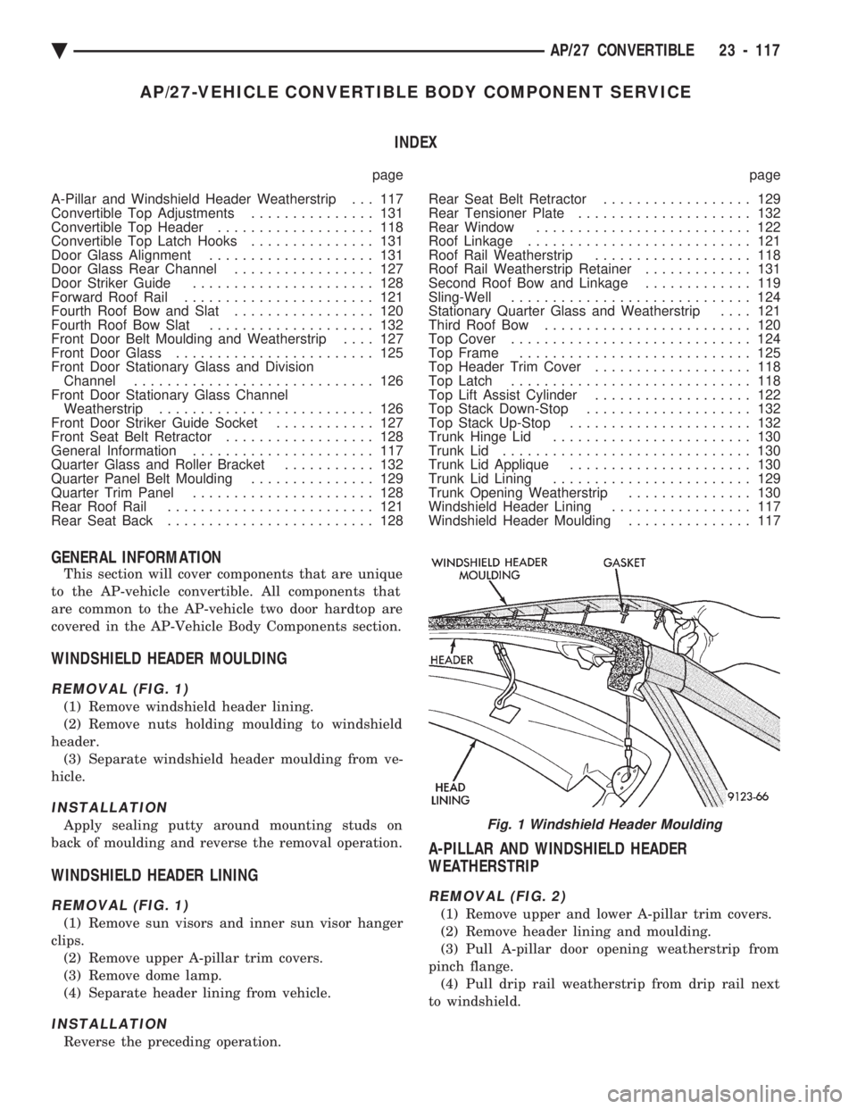
WINDSHIELD HEADER MOULDING
REMOVAL (FIG. 1)
(1) Remove windshield header lining.
(2) Remove nuts holding moulding to windshield
header. (3) Separate windshield header moulding from ve-
hicle.
INSTALLATION
Apply sealing putty around mounting studs on
back of moulding and reverse the removal operation.
WINDSHIELD HEADER LINING
REMOVAL (FIG. 1)
(1) Remove sun visors and inner sun visor hanger
clips. (2) Remove upper A-pillar trim covers.
(3) Remove dome lamp.
(4) Separate header lining from vehicle.
INSTALLATION
Reverse the preceding operation.
A-PILLAR AND WINDSHIELD HEADER
WEATHERSTRIP
REMOVAL (FIG. 2)
(1) Remove upper and lower A-pillar trim covers.
(2) Remove header lining and moulding.
(3) Pull A-pillar door opening weatherstrip from
pinch flange. (4) Pull drip rail weatherstrip from drip rail next
to windshield.
Fig. 1 Windshield Header Moulding
Ä AP/27 CONVERTIBLE 23 - 117