1993 CHEVROLET PLYMOUTH ACCLAIM seat adjustment
[x] Cancel search: seat adjustmentPage 60 of 2438

FRONT SUSPENSION
FRONT SUSPENSION MAJOR COMPONENTS (FIG. 2)
STRUT SUPPORT
The system is supported by coil springs positioned
offset around the struts. The springs are contained
between an upper seat, located just below the top
strut mount assembly (Fig. 2) and a lower spring
seat on the strut lower housing. The top of each strut assembly is bolted to the up-
per fender reinforcement (shock tower) through a
rubber isolated mount. The bottom attaches to the top of the steering
knuckle with two through bolts. On some vehicles,
one bolt has an eccentric cam located below the head
of the bolt for camber adjustment. On the other ve-
hicles the camber adjustment is done by manually
moving the steering knuckle within the strut assem-
bly. Caster is a fixed setting on all vehicles and is
not adjustable.
STEERING KNUCKLE
The steering knuckle is a single casting with legs
machined for attachment to the strut damper, steer-
ing linkage, brake adaptor, and lower control arm
ball joint. The knuckle also holds the front drive hub
bearing. The hub is positioned through the bearing
and knuckle, with the constant velocity stub shaft
splined through the hub.
LOWER CONTROL ARM
The lower control arm is a steel casting with 2
large spool type rubber pivot bushings. The lower
control arm is bolted to the crossmember with pivot
bolts through the center of the rubber pivot bush-
ings. The ball joint is pressed into the control arm and
has a non-tapered stud with a notch for clamp bolt
clearance. The stud is clamped and locked into the
steering knuckle leg with a clamp bolt. The lower control arms are inter-connected through
a rubber isolated sway bar (Fig. 2).
DRIVESHAFTS
A left and right driveshaft is attached inboard to
the transaxle differential side gears, and outboard to
the driven wheel hub. To deliver driving force from the transaxle to the
front wheels during turning maneuvers and suspen-
sion movement. Both shafts are constructed with con-
stant velocity universal joints at both ends. Both shafts have a Tripod (sliding) joint at the
transaxle end and Rzeppa joints (with splined stub
shafts) on the hub ends. Due to the transaxle loca-
tion the connecting shafts between the C/V joints are
of different length and construction. The right shaft
is longer and of tubular construction. The left shaft
is solid.
2 - 2 SUSPENSION AND DRIVESHAFTS Ä
Page 156 of 2438

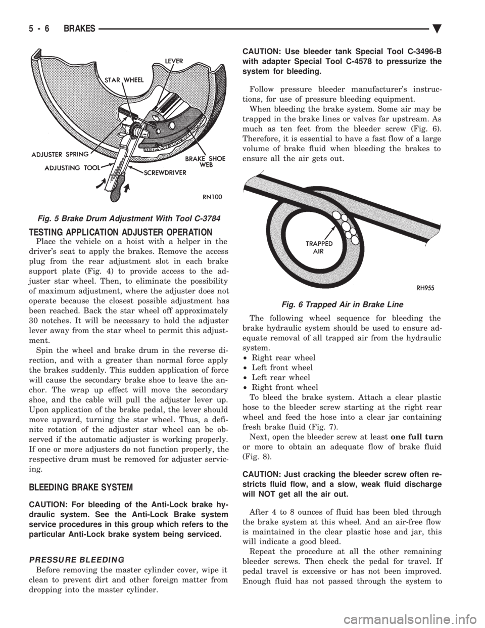
TESTING APPLICATION ADJUSTER OPERATION
Place the vehicle on a hoist with a helper in the
driver's seat to apply the brakes. Remove the access
plug from the rear adjustment slot in each brake
support plate (Fig. 4) to provide access to the ad-
juster star wheel. Then, to eliminate the possibility
of maximum adjustment, where the adjuster does not
operate because the closest possible adjustment has
been reached. Back the star wheel off approximately
30 notches. It will be necessary to hold the adjuster
lever away from the star wheel to permit this adjust-
ment. Spin the wheel and brake drum in the reverse di-
rection, and with a greater than normal force apply
the brakes suddenly. This sudden application of force
will cause the secondary brake shoe to leave the an-
chor. The wrap up effect will move the secondary
shoe, and the cable will pull the adjuster lever up.
Upon application of the brake pedal, the lever should
move upward, turning the star wheel. Thus, a defi-
nite rotation of the adjuster star wheel can be ob-
served if the automatic adjuster is working properly.
If one or more adjusters do not function properly, the
respective drum must be removed for adjuster servic-
ing.
BLEEDING BRAKE SYSTEM
CAUTION: For bleeding of the Anti-Lock brake hy-
draulic system. See the Anti-Lock Brake system
service procedures in this group which refers to the
particular Anti-Lock brake system being serviced.
PRESSURE BLEEDING
Before removing the master cylinder cover, wipe it
clean to prevent dirt and other foreign matter from
dropping into the master cylinder. CAUTION: Use bleeder tank Special Tool C-3496-B
with adapter Special Tool C-4578 to pressurize the
system for bleeding.
Follow pressure bleeder manufacturer's instruc-
tions, for use of pressure bleeding equipment. When bleeding the brake system. Some air may be
trapped in the brake lines or valves far upstream. As
much as ten feet from the bleeder screw (Fig. 6).
Therefore, it is essential to have a fast flow of a large
volume of brake fluid when bleeding the brakes to
ensure all the air gets out.
The following wheel sequence for bleeding the
brake hydraulic system should be used to ensure ad-
equate removal of all trapped air from the hydraulic
system.
² Right rear wheel
² Left front wheel
² Left rear wheel
² Right front wheel
To bleed the brake system. Attach a clear plastic
hose to the bleeder screw starting at the right rear
wheel and feed the hose into a clear jar containing
fresh brake fluid (Fig. 7). Next, open the bleeder screw at least one full turn
or more to obtain an adequate flow of brake fluid
(Fig. 8).
CAUTION: Just cracking the bleeder screw often re-
stricts fluid flow, and a slow, weak fluid discharge
will NOT get all the air out.
After 4 to 8 ounces of fluid has been bled through
the brake system at this wheel. And an air-free flow
is maintained in the clear plastic hose and jar, this
will indicate a good bleed. Repeat the procedure at all the other remaining
bleeder screws. Then check the pedal for travel. If
pedal travel is excessive or has not been improved.
Enough fluid has not passed through the system to
Fig. 5 Brake Drum Adjustment With Tool C-3784
Fig. 6 Trapped Air in Brake Line
5 - 6 BRAKES Ä
Page 163 of 2438

(3) Position the tubing in the jaws of the Flaring
Tool so that it is flush with the top surface of the
flaring tool bar assembly. (See Fig. 17). (4) Install the correct size adaptor for the brake
tubing being flared, on the feed screw of the yoke as-
sembly. Center the yoke and adapter over the end of
the tubing. Apply lubricant to the adapter area that
contacts brake tubing. Making sure the adapter pilot
is fully inserted in the end of the brake tubing.
Screw in the feed screw of the yoke assembly until
the adaptor has seated squarely on the surface of the
bar assembly (Fig. 17). This process has created the
(metric) ISO tubing flare.STOP LAMP SWITCH ADJUSTMENT (ALL
VEHICLES)
The stop lamp switch incorporates a self adjusting
feature. If adjustment or replacement is required,
proceed as follows: Install the switch in the retaining
bracket and push the switch forward as far as it will
go. The brake pedal will move forward slightly (Fig.
18). Gently pull back on the brake pedal bringing the
striker back toward the switch until the brake pedal
will go back no further. This will cause the switch to
ratchet backward to the correct position. Very little
movement is required, and no further adjustment is
necessary.
Fig. 17 ISO Tubing Flare ProcessFig. 18 Stop Lamp Switch
BASIC DIAGNOSIS GUIDE
Ä BRAKES 5 - 13
Page 168 of 2438

REAR WHEEL DRUM BRAKES INDEX
page page
Brake Drum Refacing ..................... 21
Brake Shoe Assemblies ................... 19 Description
............................. 18
Service Procedures ....................... 18
DESCRIPTION
Rear wheel drum brakes (Fig .2&3)aretwoshoe,
internal expanding type with an automatic adjuster
screw assembly that is activated each time the
brakes are applied. The automatic adjuster screw is
located directly below the wheel cylinder as shown in
figure (Fig .2&3).
WARNING: DUST AND DIRT ON BRAKE PARTS
GENERATED DURING THE NORMAL USE AND
WEAR OF MOTOR VEHICLE BRAKE SYSTEMS MAY
CONTAIN ASBESTOS FIBERS. BREATHING EXCES-
SIVE CONCENTRATIONS OF ASBESTOS FIBERS
CAN CAUSE SERIOUS BODILY HARM, SUCH AS
ASBESTOSIS AND CANCER. EXTREME CARE
SHOULD BE EXERCISED WHILE SERVICING
BRAKE ASSEMBLIES OR COMPONENTS. DO NOT CLEAN BRAKE ASSEMBLIES OR COM-
PONENTS WITH COMPRESSED AIR OR BY DRY
BRUSHING; USE A VACUUM CLEANER SPECIFI-
CALLY RECOMMENDED FOR USE WITH ASBES-
TOS FIBERS. IF A SUITABLE VACUUM CLEANER IS
NOT AVAILABLE, CLEANING SHOULD BE DONE
WET USING A WATER DAMPENED CLOTH. DO NOT CREATE DUST BY SANDING, GRINDING,
AND/OR SHAVING BRAKE LININGS OR PADS UN-
LESS SUCH OPERATION IS DONE WHILE USING
PROPERLY EXHAUST VENTILATED EQUIPMENT. DISPOSE OF ALL DUST AND DIRT SUSPECTED
TO CONTAIN ANY ASBESTOS FIBERS IN SEALED
BAGS OR CONTAINERS TO MINIMIZE DUST EXPO-
SURE TO YOURSELF AND OTHERS. FOLLOW ALL RECOMMENDED PRACTICES PRE-
SCRIBED BY THE OCCUPATIONAL SAFETY AND
HEALTH ADMINISTRATION AND THE ENVIRON-
MENTAL PROTECTION AGENCY. FOR THE HAN-
DLING, PROCESSING, AND DISPOSITION OF DUST
OR DIRT WHICH MAY CONTAIN ASBESTOS FI-
BERS. IT IS RECOMMENDED NOT TO BREATH ANY
TYPE OF BRAKE LINING MATERIAL DUST EVEN
ASBESTOS FREE, DUE TO THE FIBROUS NATURE
OF THE MATERIALS BEING USED.
SERVICE PROCEDURES
REAR BRAKE DRUM REMOVAL
If the rear brake drum is difficult to remove, fur-
ther clearance can be obtained by backing off the
brake automatic adjuster screw. Remove rubber plug
from the top of the support plate and rotate the au-
tomatic adjuster screw assembly with an upward mo-
tion, using the Brake Adjuster, Special Tool C-3784. See adjusting rear service brakes in the Service
Adjustments section in this group of the service man-
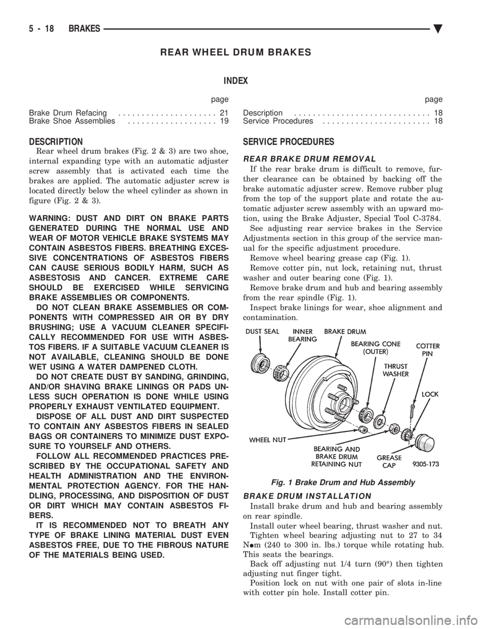
ual for the specific adjustment procedure. Remove wheel bearing grease cap (Fig. 1).
Remove cotter pin, nut lock, retaining nut, thrust
washer and outer bearing cone (Fig. 1). Remove brake drum and hub and bearing assembly
from the rear spindle (Fig. 1). Inspect brake linings for wear, shoe alignment and
contamination.
BRAKE DRUM INSTALLATION
Install brake drum and hub and bearing assembly
on rear spindle. Install outer wheel bearing, thrust washer and nut.
Tighten wheel bearing adjusting nut to 27 to 34
N Im (240 to 300 in. lbs.) torque while rotating hub.
This seats the bearings. Back off adjusting nut 1/4 turn (90É) then tighten
adjusting nut finger tight. Position lock on nut with one pair of slots in-line
with cotter pin hole. Install cotter pin.
Fig. 1 Brake Drum and Hub Assembly
5 - 18 BRAKES Ä
Page 211 of 2438

WARNING: THE SELF ADJUSTING FEATURE OF THIS
PARKING BRAKE LEVER ASSEMBLY CONTAINS A
CLOCK SPRING LOADED TO APPROXIMATELY 30
POUNDS. CARE MUST BE TAKEN TO PREVENT EX-
CESSIVE JARRING OF THE ASSEMBLY. DO NOT
RELEASE THE SELF ADJUSTER LOCKOUT DEVICE
BEFORE INSTALLING CABLES INTO THE EQUAL-
IZER. KEEP HANDS OUT OF SELF ADJUSTER SEC-
TOR AND PAWL AREA. FAILURE TO OBSERVE CAU-
TION IN HANDLING THIS MECHANISM COULD LEAD
TO SERIOUS INJURY.
When repairs to the hand lever assembly or cable
system are required the self adjuster must be reloaded
and locked out.
SELF ADJUSTING PROCEDURES (AG & AJ BODY)
TO RELOAD SELF ADJUSTER
(1) Remove ash receiver or courtesy light from rear
of center console to gain access to self adjuster. Also,
remove carpet from sides of console. (2) Pull on equalizer/output cable to wind up sprin-
g(requires greater than 30 pounds effort). Continue
until self adjuster lockout pawl is positioned about
midway on the self adjuster sector (Fig. 6). Rotate
lockout pawl into self adjuster sector by turning allen
screw clockwise. Rotating lockout device requires
very little effort. Do not force or failure of lock-
out device will occur. (3) When repairs are complete, adjust rear brakes
before adjusting parking brake. On drum-in-hat type of
rear disc brake adjust shoe diameter to 171.5 mm (6.75
inch).
ADJUST PARKING BRAKE (AG & AJ BODY)
Be sure that the cables are properly assembled to the
equalizer bracket prior to cable adjustment. (1) Insert a 7/32 inch allen wrench into hex socket
and turn counter-clockwise through approximately 15É
of rotation (Fig. 4). In turning lockout device, self
adjuster release is a loud snapping noise followed by
reaching a more felt than heard detent. Very light
effort is required to seat lockout arm into detent.
Follow through to the detent is important in prevent-
ing the lockout rod from rattling. Note: The parking brake handle can be in any
position when releasing self adjuster. (2) Cycle lever to position cables. Rear wheels should
rotate freely without dragging.
REAR PARKING BRAKE CABLE REMOVAL (AA, AC,
AP, AY BODY)
The rear brake cables are attached to rear connec-
tors. Should it become necessary to remove either parking
brake cable for installation of a new cable, proceed as
follows: With vehicle jacked up on a suitable hoist, remove
wheel and tire assembly (Fig. 6). Back off cable adjusting nut to provide slack and
disconnect rear brake cable from connector.
DRUM BRAKES
(1) Disconnect park brake cable from park brake
lever in rear wheel brakes. (2) Using an aircraft type hose clamp compress re-
tainers on end of cable housing and start cable out of
retaining hole in the support plate. Remove clamp
when retainers are free of the mounting hole in the
support plate, (Fig. 6).
(3) Remove clip from brake cable at support
bracket and pull cable away from trailing arm as-
sembly (Figs. 3 and 4).
DISC BRAKES
(1) Remove disc brake caliper from adapter, and
brake disc (rotor) from rear hub.
Fig. 5 Self Adjusting Parking Brake Lever Assembly
Fig. 6 Removing Brake Cable from Support Plate
Ä BRAKES 5 - 61
Page 336 of 2438

CLUTCH PEDAL POSITION SWITCH
The clutch pedal position switch functions as a
safety interlock device. It prevents possible engine
cranking with the clutch engaged. The clutch pedal position switch is wired in series
between the starter relay coil and the ignition
switch. The clutch pedal position switch is mounted to a
bracket located next to the clutch pedal. The switch
is held in place by four plastic wing tabs. The clutch pedal position switch has an adjustable
striker plate. The striker plate is located on the left
side of the clutch pedal (Fig. 3).
DIAGNOSIS
Disconnect clutch pedal position switch harness
from instrument panel wiring harness. Using a ohm
meter, check for continuity between the two termi-
nals in the connector on the switch harness. There
should be no continuity between the terminals when
the switch is in its neutral (fully extended) position.
When the switch is depressed more than 1.25 mm
(0.050) the ohm meter should show continuity. If all ohm meter readings are correct and the
switch does not operate correctly, adjustment is re-
quired. Refer to Switch Adjustment Procedure to ad-
just switch.
REMOVAL
(1) Disconnect electrical harness to switch connec-
tor. (2) Depress wing tabs on switch and push switch out
of mounting bracket. Then slide wires through slot in
bracket.
INSTALLATION
(1) Slide switch wires through slot in switch bracket.
(2) Line up switch tab with slot in switch bracket
and push switch into position. Do not pull on the switch
wires to seat switch into bracket, switch damage may
occur. (3) After installation, the switch must be adjusted
and checked for proper operation. Refer to Switch
Adjustment Procedure.
ADJUSTMENT PROCEDURE
When performing switch adjustment, the floor mat
should be removed before beginning adjustment proce-
dures. (1) Set the park brake.
(2) Disconnect clutch cable at the transaxle end of
the cable. (3) Depress clutch pedal, loosen adjusting nut and
slide the striker plate forward to fully compress the
clutch pedal position switch plunger. (4) Tighten adjusting nut to 12 N Im (105 in. lbs.).
(5) Reconnect clutch cable.
The clutch pedal position switch is now ad-
justed. A final check is required to insure that the
switch is ``made'' below the clutch release point. (1) With the park brake set and the vehicle IN
NEUTRAL turn the key to the start position. The
vehicle should not crank. If the vehicle cranks do
not continue with this test. Recheck the switch and
switch adjustment to determine the cause. If the ve-
hicle does not crank proceed to step 2. (2) With the park brake set and the vehicle IN
GEAR turn the key to the start position.
WARNING: BEFORE PERFORMING STEP THREE BE
SURE THAT THE AREA IN FRONT OF THE VEHICLE
IS CLEAR OF OBSTRUCTIONS AND PEOPLE. VE-
HICLE MAY MOVE WHEN PERFORMING THIS TEST.
(3) Slowly depress the clutch pedal and feel for any
vehicle motion when the starter is energized. If there is
no motion the switch is properly adjusted. If motion is
felt, repeat the adjustment procedure.
Fig. 3 Clutch Pedal Position Switch and Components
6 - 4 MANUAL TRANSAXLE CLUTCH Ä
Page 1568 of 2438

The MOPAR Silicone Rubber Adhesive Sealant
gasket material or equivalent should be applied in a
continuous bead approximately 3mm (0.120 inch) in
diameter. All mounting holes must be circled. For
corner sealing, a 3.17 or 6.35 mm (1/8 or 1/4 inch.)
drop is placed in the center of the gasket contact
area. Uncured sealant may be removed with a shop
towels. Components should be torqued in place while
the sealant is still wet to the touch (within 10 min-
utes). The usage of a locating dowel is recommended
during assembly to prevent smearing of material off
location.
CRANKSHAFT SPROCKET BOLT ACCESS PLUG
An Access plug is located in the right inner fender
shield. Remove the plug and insert proper size
socket, extension and rachet, when crankshaft rota-
tion is necessary.
ENGINE PERFORMANCE
If a loss of performance is noticed, ignition timing
should be checked. If ignition timing is retarded by
9, 18 or 27É indicating 1, 2 or 3 (timing belt or chain)
teeth may have skipped, then, camshaft and acces-
sory shaft timing with the crankshaft should be
checked. Refer to Engine Timing Sprockets and Oil
Seals of the Engine Section. To provide best vehicle performance and lowest ve-
hicle emissions, it is most important that the tune-up
be done accurately. Use the specifications listed on
the Vehicle Emission Control Information label
found in the engine compartment. (1) Test cranking amperage draw. See Starting
Motor Cranking Amperage Draw Electrical Section
of this manual. (2) Tighten the intake manifold bolts to specifica-
tions. (3) Perform cylinder compression test.(a) Check engine oil level and add oil if neces-
sary. (b) Drive the vehicle until engine reaches normal
operating temperature. (c) Select a route free from traffic and other
forms of congestion, observe all traffic laws, and ac-
celerate through the gears several times briskly.
CAUTION: Do not overspeed the engine. The higher
engine speed may help clean out valve seat deposits
which can prevent accurate compression readings.
(d) Remove all spark plugs from engine. As
spark plugs are being removed, check electrodes for
abnormal firing indicators fouled, hot, oily, etc.
Record cylinder number of spark plug for future
reference. (e) Disconnect coil wire from distributor and se-
cure to good ground to prevent a spark from start- ing a fire (Conventional Ignition System). For Direct
Ignition System DIS disconnect the coil connector. (f) Be sure throttle blade is fully open during the
compression check. (g) Insert compression gage adaptor into the #1
spark plug hole in cylinder head. Crank engine until
maximum pressure is reached on gage. Record this
pressure as #1 cylinder pressure. (h) Repeat Step G for all remaining cylinders.
(i) Compression should not be less than (689kPa)
100 psi and not vary more than 25 percent from
cylinder to cylinder. (j) If one or more cylinders have abnormally low
compression pressures, repeat steps 3b through 3h. (k) If the same cylinder or cylinders repeat an
abnormally low reading on the second compression
test, it could indicate the existence of a problem in
the cylinder in question.
The recommended compression pressures are
to be used only as a guide to diagnosing engine
problems. An engine should not be disassembled
to determine the cause of low compression un-
less some malfunction is present. (4) Clean or replace spark plugs as necessary and
adjust gap as specified in Electrical Group 8. Tighten to
specifications. (5) Test resistance of spark plug cables. Refer to
Ignition System Secondary Circuit Inspection Electri-
cal Section Group 8. (6) Inspect the primary wire. Test coil output volt-
age, primary and secondary resistance. Replace parts
as necessary. Refer to Ignition System and make nec-
essary adjustment. (7) Ignition timing should be set to specifications.
(See Specification Label in engine compartment). (8) Test fuel pump for pressure and vacuum. Refer to
Fuel System Group 14, Specifications. (9) The air filter elements should be replaced as
specified in Lubrication and Maintenance, Group 0. (10) Inspect crankcase ventilation system as out
lined in Lubrication and Maintenance, Group 0. For
emission controls see Emission Controls Group 25 for
service procedures. (11) Inspect and adjust accessory belt drives refer-
ring to Accessory Belt Drive in Cooling System, Group
7 for proper adjustments. (12) Road test vehicle as a final test.
HONING CYLINDER BORES
Before honing, stuff plenty of clean shop towels
under the bores, over the crankshaft to keep abrasive
materials from entering crankcase area. (1) Used carefully, the cylinder bore resizing hone
C-823 equipped with 220 grit stones, is the best tool for
this job. In addition to deglazing, it will reduce taper
and out-of-round as well as removing light
9 - 2 ENGINE Ä
Page 1578 of 2438

ENGINE MOUNTS
REMOVAL AND INSTALLATION RIGHT SIDE MOUNT
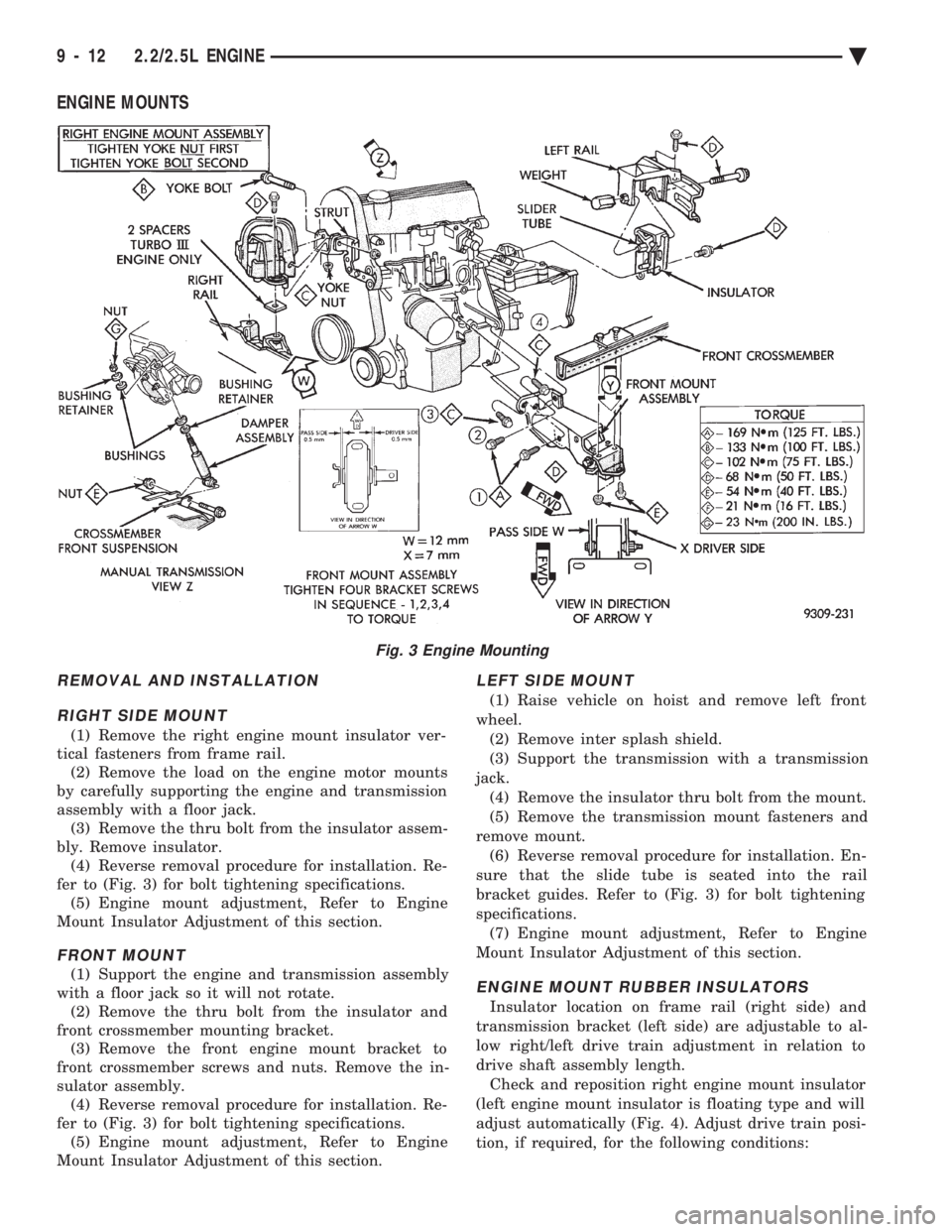
(1) Remove the right engine mount insulator ver-
tical fasteners from frame rail. (2) Remove the load on the engine motor mounts
by carefully supporting the engine and transmission
assembly with a floor jack. (3) Remove the thru bolt from the insulator assem-
bly. Remove insulator. (4) Reverse removal procedure for installation. Re-
fer to (Fig. 3) for bolt tightening specifications. (5) Engine mount adjustment, Refer to Engine
Mount Insulator Adjustment of this section.
FRONT MOUNT
(1) Support the engine and transmission assembly
with a floor jack so it will not rotate. (2) Remove the thru bolt from the insulator and
front crossmember mounting bracket. (3) Remove the front engine mount bracket to
front crossmember screws and nuts. Remove the in-
sulator assembly. (4) Reverse removal procedure for installation. Re-
fer to (Fig. 3) for bolt tightening specifications. (5) Engine mount adjustment, Refer to Engine
Mount Insulator Adjustment of this section.
LEFT SIDE MOUNT
(1) Raise vehicle on hoist and remove left front
wheel. (2) Remove inter splash shield.
(3) Support the transmission with a transmission
jack. (4) Remove the insulator thru bolt from the mount.
(5) Remove the transmission mount fasteners and
remove mount. (6) Reverse removal procedure for installation. En-
sure that the slide tube is seated into the rail
bracket guides. Refer to (Fig. 3) for bolt tightening
specifications. (7) Engine mount adjustment, Refer to Engine
Mount Insulator Adjustment of this section.
ENGINE MOUNT RUBBER INSULATORS
Insulator location on frame rail (right side) and
transmission bracket (left side) are adjustable to al-
low right/left drive train adjustment in relation to
drive shaft assembly length. Check and reposition right engine mount insulator
(left engine mount insulator is floating type and will
adjust automatically (Fig. 4). Adjust drive train posi-
tion, if required, for the following conditions:
Fig. 3 Engine Mounting
9 - 12 2.2/2.5L ENGINE Ä