1993 CHEVROLET PLYMOUTH ACCLAIM seat adjustment
[x] Cancel search: seat adjustmentPage 1992 of 2438
ing seat will give a false end play reading while
gauging for proper shims. Improperly seated bearing
cups and cones are subject to low mileage failure.(2) Bearing cups and cones should be replaced if they
show signs of pitting or heat distress. If distress is seen
on either the cup or bearing rollers, both cup and cone
must be replaced. (3) Bearing preload and drag torque specifications
must be maintained to avoid premature bearing
failures. Used (original) bearing may lose up to 50% of
the original drag torque after break in. All bearing
adjustments must be made with no other compo-
nent interference or gear intermesh. (4) Replace bearings as a pair. For example, if one
differential bearing is defective, replace both differen-
tial bearings. If one input shaft bearing is defective,
replace both input shaft bearings. (5) Bearing cones must notbe reused if removed.
(6) Turning torque readings should be obtained
while smoothly rotating in either direction (break-
away reading is not indicative of the true turning
torque). (7) Replace oil baffle, if damaged.
INPUT SHAFT BEARING END PLAY ADJUST-MENT
(1) Using Tool C-4656 with Handle C-4171, press
input shaft front bearing cup slightly forward in case.
Then, using Tool C-4655 with Handle C-4171, press
bearing cup back into case from the front. Properly
position bearing cup, before checking input shaft end
play (see input shaft front bearing cup replace in
Subassembly Recondition section).This step is
not necessary if Tool C-4655 was previously used
to install input shaft front bearing cup in the
case. Also no input shaft shim has been installed
since pressing cup into case. (2) Select a gauging shim which will give 0.025 to
0.254mm (.001 to .010 inch) end play. SUGGESTION:
Measure original shim from input shaft seal retainer and select a shim 0.254mm (.010
inch) thinner than original for the gauging shim.
(3) Install gauging shim on bearing cup and install
input shaft seal retainer.
CAUTION: The input shaft seal retainer is used to
draw the input shaft front bearing cup the proper
distance into the case bore during this step. Alter-
nately tighten input shaft seal retainer bolts until
input shaft seal retainer is bottomed against case.
Tighten bolts to 28 N Im (21 ft. lbs.).
(4) Oil input shaft bearings with SAE 5W-30 engine
oil and install input shaft in case. Install bearing
retainer plate with input shaft rear bearing cup
pressed in and bearing support plate installed. Tighten
all bolts and nuts to 28 N Im (21 ft. lbs.).
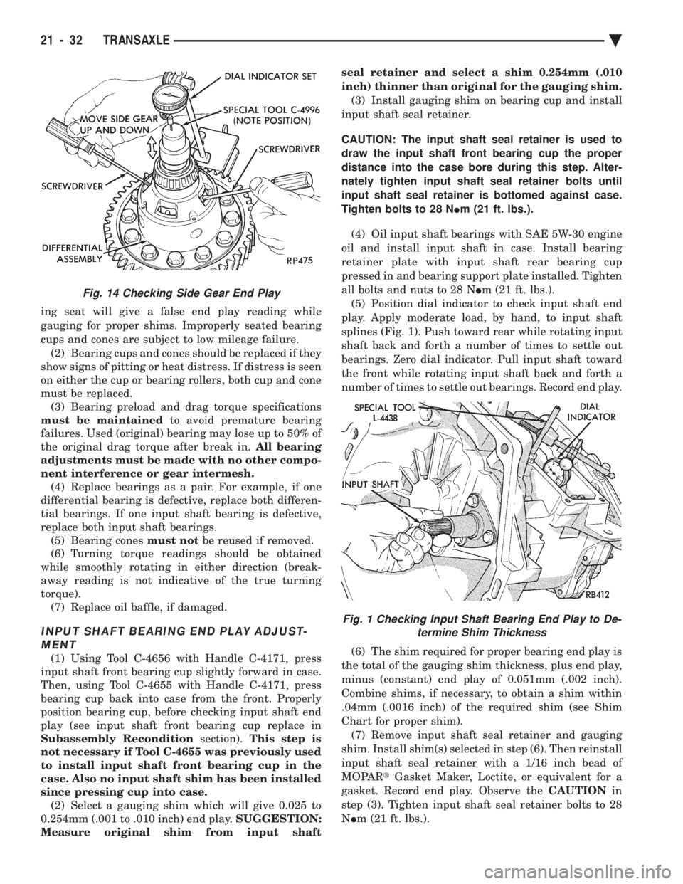
(5) Position dial indicator to check input shaft end
play. Apply moderate load, by hand, to input shaft
splines (Fig. 1). Push toward rear while rotating input
shaft back and forth a number of times to settle out
bearings. Zero dial indicator. Pull input shaft toward
the front while rotating input shaft back and forth a
number of times to settle out bearings. Record end play.
(6) The shim required for proper bearing end play is
the total of the gauging shim thickness, plus end play,
minus (constant) end play of 0.051mm (.002 inch).
Combine shims, if necessary, to obtain a shim within
.04mm (.0016 inch) of the required shim (see Shim
Chart for proper shim). (7) Remove input shaft seal retainer and gauging
shim. Install shim(s) selected in step (6). Then reinstall
input shaft seal retainer with a 1/16 inch bead of
MOPAR tGasket Maker, Loctite, or equivalent for a
gasket. Record end play. Observe the CAUTIONin
step (3). Tighten input shaft seal retainer bolts to 28
N Im (21 ft. lbs.).
Fig. 14 Checking Side Gear End Play
Fig. 1 Checking Input Shaft Bearing End Play to De-
termine Shim Thickness
21 - 32 TRANSAXLE Ä
Page 2000 of 2438
FLUID LEVEL AND CONDITION
The transmission and differential sump have a
common oil sump with a communicating opening
between the two. Before removing the dipstick, wipe all dirt off of the
protective disc and the dipstick handle. The torque converter will fill in both the PPark or N
Neutral positions. Place the selector lever in PPark to
check fluid level. Inspect fluid level on dipstick every six months.
Allow the engine to idle for at least one minute
with vehicle on level ground. This will assure
complete oil level stabilization between differen-
tial and transmission. A properly filled transaxle
will read near the addmark when fluid temperature is
21 degrees Celsius (70 degrees Fahrenheit). When the
transaxle reaches operating temperature the fluid
should be in the HOTregion.
Low fluid level can cause a variety of conditions
because it allows the pump to take in air along with the
fluid. As in any hydraulic system, air bubbles make the
fluid spongy, therefore, pressures will be low and build
up slowly. Improper filling can also raise the fluid level too
high. When the transaxle has too much fluid, the gears
churn up foam and cause the same conditions which
occur with a low fluid level. In either case, the air bubbles can cause overheating,
fluid oxidation, and varnishing, which can interfere
with normal valve, clutch, and servo operation. Foam-
ing can also result in fluid escaping from the transaxle
vent (dipstick handle) where it may be mistaken for a
leak. Along with fluid level, it is important to check the
condition of the fluid. When the fluid smells burned,
and is contaminated with metal or friction material
particles, a complete transaxle overhaul is needed. Be
sure to examine the fluid on the dipstick closely. If
there is any doubt about its condition, drain out a
sample for a double check. After the fluid has been checked, seat the dipstick
fully to seal out water and dirt.
SELECTION OF LUBRICANT
It is important that the proper lubricant be used in
these transmissions. MOPAR tATF PLUS (Automatic
Transmission Fluid-Type 7176) should be used to aid in
assuring optimum transmission performance. Fluids of
the type labeled DEXRON II Automatic Transmission
Fluid should be used only if the recommended fluid is
not available. It is important that the transmission
fluid be maintained at the prescribed level using the
recommended fluids.
SPECIAL ADDITIVES
Chrysler Corporation does not recommend the addi-
tion of any fluids to the transmission, other than the
automatic transmission fluid listed above. An ex- ception to this policy is the use of special dyes to aid in
detecting fluid leaks. The use of transmission sealers
should be avoided, since they may adversely affect
seals.
FLUID AND FILTER CHANGE
When the factory fill fluid is changed, only
fluids of the type labeled MOPAR tATF PLUS
(Automatic Transmission fluid) Type 7176 should
be used. A band adjustment and filter change
should be made at the time of the oil change. The
magnet (on the inside of the oil pan) should also
be cleaned with a clean, dry cloth. If the transaxle is disassembled for any reason,
the fluid and filter should be changed, and the
band(s) adjusted.
FLUID DRAIN AND REFILL
(1) Raise vehicle on a hoist (See Lubrication, Group
0). Place a drain container with a large opening, under
transaxle oil pan. (2) Loosen pan bolts and tap the pan at one corner to
break it loose allowing fluid to drain, then remove the
oil pan. (3) Install a new filter and gasket on bottom of the
valve body and tighten retaining screws to 5 N Im (40
in. lbs.). (4) Clean the oil pan and magnet. Reinstall pan
using new MOPAR tAdhesive sealant. Tighten oil pan
bolts to 19 N Im (165 in. lbs.).
(5) Pour four quarts of MOPAR tATF PLUS (Auto-
matic Transmission Fluid) Type 7176 through the
dipstick opening. (6) Start engine and allow to idle for at least one
minute. Then, with parking and service brakes ap-
plied, move selector lever momentarily to each posi-
tion, ending in the park or neutral position. (7) Add sufficient fluid to bring level to 1/8 inch
below the ADD mark. Recheck fluid level after transaxle is at normal
operating temperature. The level should be in the HOT
region (Fig. 1). To prevent dirt from entering transaxle, make cer-
tain that dipstick is full seated into the dipstick open-
ing.
TORQUE CONVERTER CLUTCH SOLENOID WIRING
CONNECTOR
If wiring connector is unplugged, the torque con-
verter clutch will not operate (Fig. 2).
ROAD TEST
Prior to performing a road test, be certain that the
fluid level and condition, and control cable adjustments
have been checked and approved. During the road test, the transaxle should be oper-
ated in each position to check for slipping and any
variation in shifting.
21 - 40 TRANSAXLE Ä
Page 2041 of 2438
Remove old sealant before applying new seal-
ant. Use MOPAR tAdhesive Sealant on retainer
to seal retainer to case.
BEARING ADJUSTMENT PROCEDURES
GENERAL RULES ON SERVICING BEARINGS
(1) Take extreme care when removing and in stalling
bearing cups and cones. Use only an arbor press for
installation, as a hammer may not properly align the
bearing cup or cone. Burrs or nicks on the bearing seat
will give a false end play reading, while gauging for
proper shims. Improperly seated bearing cup and cones
are subject to low-mileage failure. (2) Bearing cups and cones should be replaced if they
show signs of pitting or heat distress. If distress is seen on either the cup or bearing rollers,
both cup and cone must be replaced. Bearing end play and drag torque specifica-
tions must be maintained to avoid premature
bearing failures. Used (original) bearing may lose up to 50 of the
original drag torque after break-in. All bearing adjustments must be made with no
other component interference or gear inter-
mesh, except the transfer gear bearing.
OUTPUT SHAFT BEARING
With output shaft gear removed.
(1) Install a 13.65 mm (.537 inch) and a 1.34 mm
(.053 inch) gauging shims on the planetary rear annu-
lus gear hub using grease to hold the shims in place.
The 13.65 mm shim has a larger inside diameter and
must be installed over the output shaft first. The 1.34
mm shim pilots on the output shaft. (2) Install output shaft gear and bearing assembly,
torque to 271 N Im (200 ft. lbs.).
(3) To measure bearing end play: (a) Attach Tool L-4432 to the output shaft gear.
(b) Mount a steel ball with grease into the end of
the output shaft. (c) Push and pull the gear while rotating back and
forth to insure seating of the bearing rollers. (d) Using a dial indicator, mounted to the tran-
saxle case, measure output shaft end play.
(4) Once bearing end play has been determined,
refer to the output shaft bearing shim chart for the
required shim combination to obtain proper bearing
setting. (a) The 12.65 mm (.498 inch), 13.15 mm (.518 inch)
or 13.65 mm (.537 inch) shims are always in-
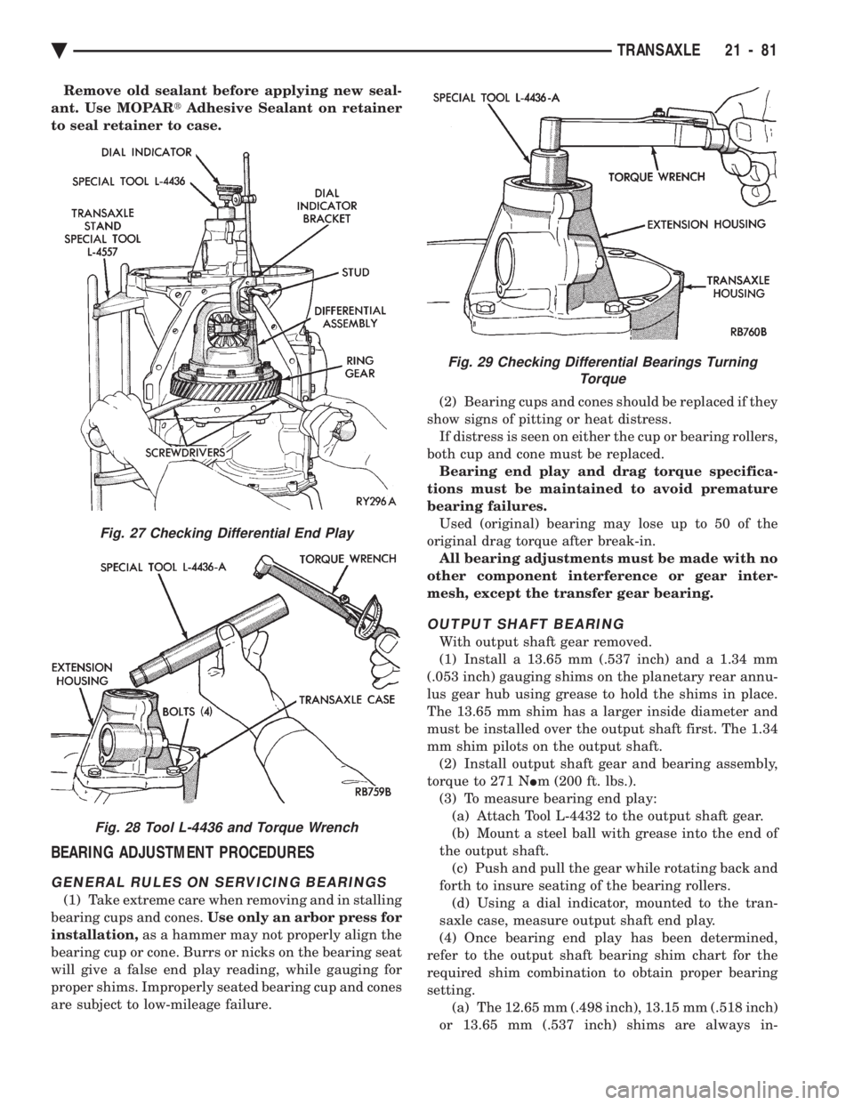
Fig. 27 Checking Differential End Play
Fig. 28 Tool L-4436 and Torque Wrench
Fig. 29 Checking Differential Bearings Turning Torque
Ä TRANSAXLE 21 - 81
Page 2080 of 2438
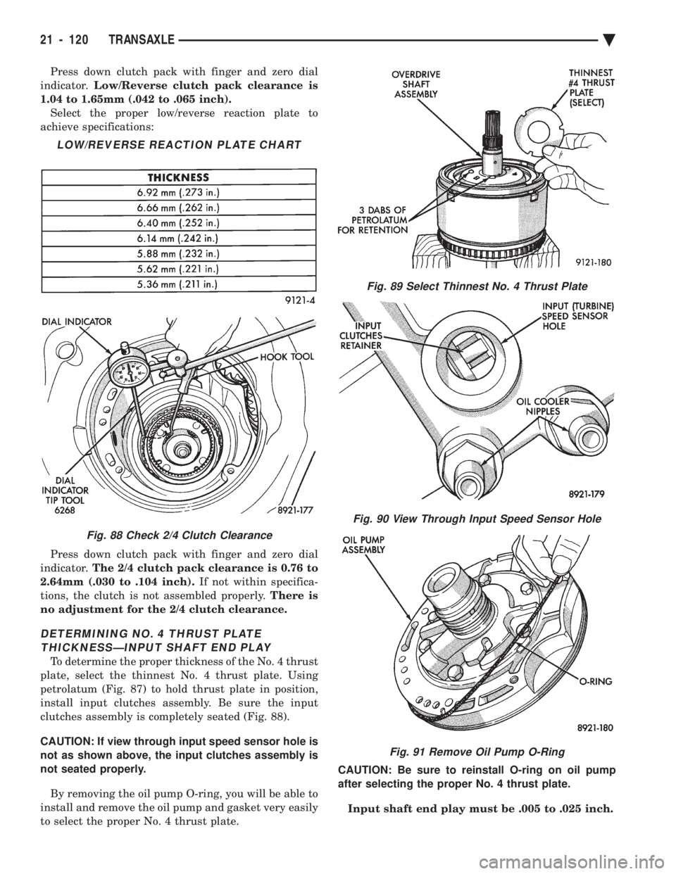
Press down clutch pack with finger and zero dial
indicator. Low/Reverse clutch pack clearance is
1.04 to 1.65mm (.042 to .065 inch). Select the proper low/reverse reaction plate to
achieve specifications:
Press down clutch pack with finger and zero dial
indicator. The 2/4 clutch pack clearance is 0.76 to
2.64mm (.030 to .104 inch). If not within specifica-
tions, the clutch is not assembled properly. There is
no adjustment for the 2/4 clutch clearance.
DETERMINING NO. 4 THRUST PLATE THICKNESSÐINPUT SHAFT END PLAY
To determine the proper thickness of the No. 4 thrust
plate, select the thinnest No. 4 thrust plate. Using
petrolatum (Fig. 87) to hold thrust plate in position,
install input clutches assembly. Be sure the input
clutches assembly is completely seated (Fig. 88).
CAUTION: If view through input speed sensor hole is
not as shown above, the input clutches assembly is
not seated properly.
By removing the oil pump O-ring, you will be able to
install and remove the oil pump and gasket very easily
to select the proper No. 4 thrust plate. CAUTION: Be sure to reinstall O-ring on oil pump
after selecting the proper No. 4 thrust plate.
Input shaft end play must be .005 to .025 inch.
LOW/REVERSE REACTION PLATE CHART
Fig. 88 Check 2/4 Clutch Clearance
Fig. 89 Select Thinnest No. 4 Thrust Plate
Fig. 90 View Through Input Speed Sensor Hole
Fig. 91 Remove Oil Pump O-Ring
21 - 120 TRANSAXLE Ä
Page 2101 of 2438
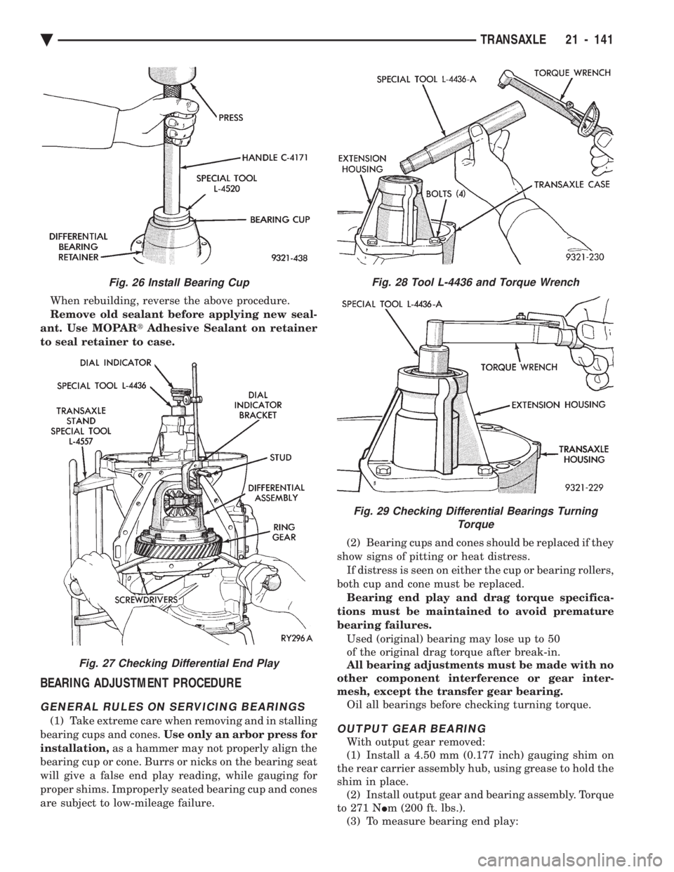
When rebuilding, reverse the above procedure.
Remove old sealant before applying new seal-
ant. Use MOPAR tAdhesive Sealant on retainer
to seal retainer to case.
BEARING ADJUSTMENT PROCEDURE
GENERAL RULES ON SERVICING BEARINGS
(1) Take extreme care when removing and in stalling
bearing cups and cones. Use only an arbor press for
installation, as a hammer may not properly align the
bearing cup or cone. Burrs or nicks on the bearing seat
will give a false end play reading, while gauging for
proper shims. Improperly seated bearing cup and cones
are subject to low-mileage failure. (2) Bearing cups and cones should be replaced if they
show signs of pitting or heat distress. If distress is seen on either the cup or bearing rollers,
both cup and cone must be replaced. Bearing end play and drag torque specifica-
tions must be maintained to avoid premature
bearing failures. Used (original) bearing may lose up to 50
of the original drag torque after break-in.
All bearing adjustments must be made with no
other component interference or gear inter-
mesh, except the transfer gear bearing. Oil all bearings before checking turning torque.OUTPUT GEAR BEARING
With output gear removed:
(1) Install a 4.50 mm (0.177 inch) gauging shim on
the rear carrier assembly hub, using grease to hold the
shim in place. (2) Install output gear and bearing assembly. Torque
to 271 N Im (200 ft. lbs.).
(3) To measure bearing end play:
Fig. 26 Install Bearing Cup
Fig. 27 Checking Differential End Play
Fig. 28 Tool L-4436 and Torque Wrench
Fig. 29 Checking Differential Bearings Turning Torque
Ä TRANSAXLE 21 - 141
Page 2163 of 2438
(2) position wind deflector so 19 mm (0.75 in.)
above top surface of roof panel and 1 mm (0.040 in.)
rearward of roof panel forward edge. (3) Secure wind deflector to sunroof unit.
GLASS PANEL
GLASS PANEL REMOVAL
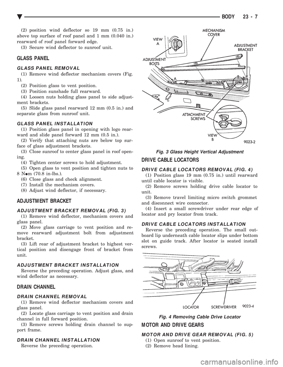
(1) Remove wind deflector mechanism covers (Fig.
1). (2) Position glass to vent position.
(3) Position sunshade full rearward.
(4) Loosen nuts holding glass panel to side adjust-
ment brackets. (5) Slide glass panel rearward 12 mm (0.5 in.) and
separate glass from sunroof unit.
GLASS PANEL INSTALLATION
(1) Position glass panel in opening with logo rear-
ward and slide panel forward 12 mm (0.5 in.). (2) Verify that attaching nuts are below top sur-
face of glass adjustment brackets. (3) Close sunroof to center glass panel in roof open-
ing. (4) Tighten center screws to hold adjustment.
(5) Open glass to vent position and tighten nuts to
8N Im (70.8 in-lbs.).
(6) Close glass and check alignment.
(7) Install the mechanism covers.
(8) Adjust wind deflector, if necessary.
ADJUSTMENT BRACKET
ADJUSTMENT BRACKET REMOVAL (FIG. 3)
(1) Remove wind deflector, mechanism covers and
glass panel. (2) Move glass carriage to vent position and re-
move rearward adjustment bolt from adjustment
bracket. (3) Lift rear of adjustment bracket to highest ver-
tical position and disengage front of bracket from
unit.
ADJUSTMENT BRACKET INSTALLATION
Reverse the preceding operation. Adjust glass, and
wind deflector as necessary.
DRAIN CHANNEL
DRAIN CHANNEL REMOVAL
(1) Remove wind deflector mechanism covers and
glass panel. (2) Locate glass carriage to vent position and drain
channel in full forward position. (3) Remove screws holding drain channel to sup-
port frame.
DRAIN CHANNEL INSTALLATION
Reverse the preceding operation.
DRIVE CABLE LOCATORS
DRIVE CABLE LOCATORS REMOVAL (FIG. 4)
(1) Position glass 19 mm (0.75 in.) until rearward
until cable locator is visible. (2) Remove screws holding drive cable locator to
unit. (3) Remove travel limiting micro switch grommet
and disconnect wire connector. (4) Insert a small screwdriver under rear edge of
locator and pry locator from track.
DRIVE CABLE LOCATORS INSTALLATION
Reverse the preceding operation. The small out-
board lip underneath cable locator slips under bottom
slot on guide track. After locator is seated install
screws.
MOTOR AND DRIVE GEARS
MOTOR AND DRIVE GEAR REMOVAL (FIG. 5)
(1) Open sunroof to vent position.
(2) Remove head lining.
Fig. 3 Glass Height Vertical Adjustment
Fig. 4 Removing Cable Drive Locator
Ä BODY 23 - 7
Page 2186 of 2438
INSTALLATION
Reverse the preceding operation. On vehicles with
automatic transaxle, verify gear selector indicator
adjustment before returning vehicle to use.
FLOOR CARPET
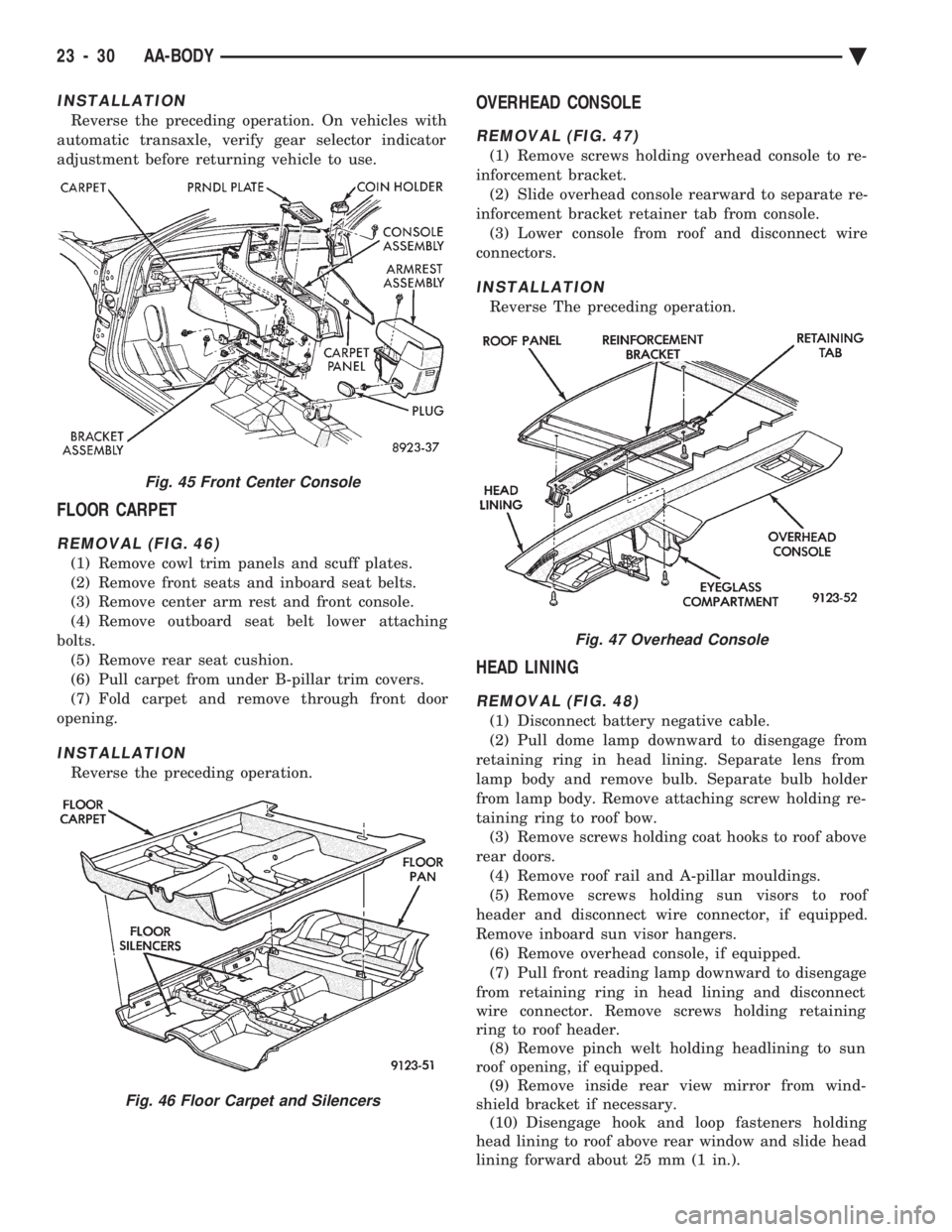
REMOVAL (FIG. 46)
(1) Remove cowl trim panels and scuff plates.
(2) Remove front seats and inboard seat belts.
(3) Remove center arm rest and front console.
(4) Remove outboard seat belt lower attaching
bolts. (5) Remove rear seat cushion.
(6) Pull carpet from under B-pillar trim covers.
(7) Fold carpet and remove through front door
opening.
INSTALLATION
Reverse the preceding operation.
OVERHEAD CONSOLE
REMOVAL (FIG. 47)
(1) Remove screws holding overhead console to re-
inforcement bracket. (2) Slide overhead console rearward to separate re-
inforcement bracket retainer tab from console. (3) Lower console from roof and disconnect wire
connectors.
INSTALLATION
Reverse The preceding operation.
HEAD LINING
REMOVAL (FIG. 48)
(1) Disconnect battery negative cable.
(2) Pull dome lamp downward to disengage from
retaining ring in head lining. Separate lens from
lamp body and remove bulb. Separate bulb holder
from lamp body. Remove attaching screw holding re-
taining ring to roof bow. (3) Remove screws holding coat hooks to roof above
rear doors. (4) Remove roof rail and A-pillar mouldings.
(5) Remove screws holding sun visors to roof
header and disconnect wire connector, if equipped.
Remove inboard sun visor hangers. (6) Remove overhead console, if equipped.
(7) Pull front reading lamp downward to disengage
from retaining ring in head lining and disconnect
wire connector. Remove screws holding retaining
ring to roof header. (8) Remove pinch welt holding headlining to sun
roof opening, if equipped. (9) Remove inside rear view mirror from wind-
shield bracket if necessary. (10) Disengage hook and loop fasteners holding
head lining to roof above rear window and slide head
lining forward about 25 mm (1 in.).
Fig. 45 Front Center Console
Fig. 46 Floor Carpet and Silencers
Fig. 47 Overhead Console
23 - 30 AA-BODY Ä
Page 2212 of 2438
mm (0.240 in) gap to front door edge. All surfaces
across gaps should be flush.
DOOR TRIM PANEL
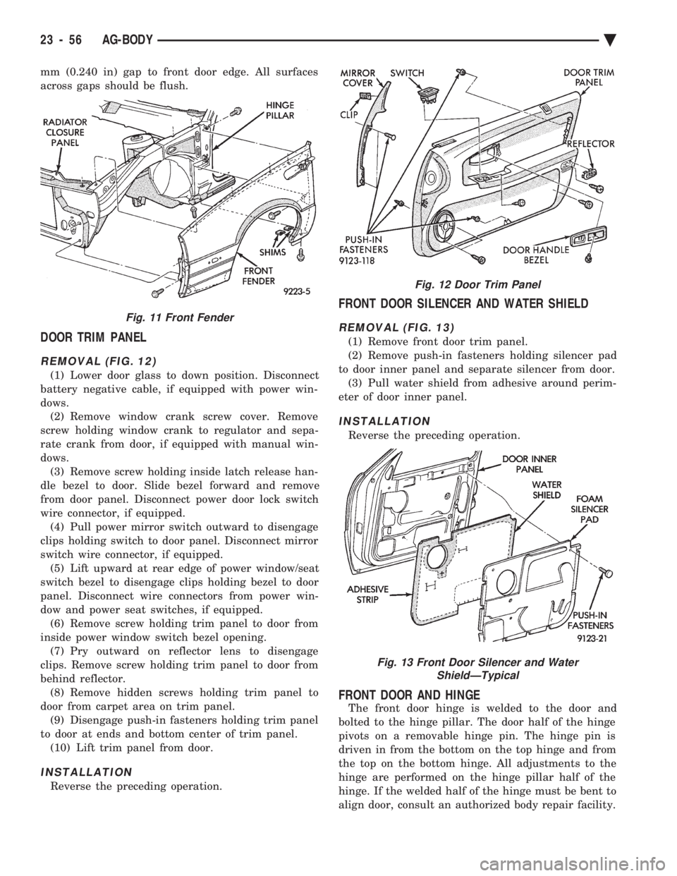
REMOVAL (FIG. 12)
(1) Lower door glass to down position. Disconnect
battery negative cable, if equipped with power win-
dows. (2) Remove window crank screw cover. Remove
screw holding window crank to regulator and sepa-
rate crank from door, if equipped with manual win-
dows. (3) Remove screw holding inside latch release han-
dle bezel to door. Slide bezel forward and remove
from door panel. Disconnect power door lock switch
wire connector, if equipped. (4) Pull power mirror switch outward to disengage
clips holding switch to door panel. Disconnect mirror
switch wire connector, if equipped. (5) Lift upward at rear edge of power window/seat
switch bezel to disengage clips holding bezel to door
panel. Disconnect wire connectors from power win-
dow and power seat switches, if equipped. (6) Remove screw holding trim panel to door from
inside power window switch bezel opening. (7) Pry outward on reflector lens to disengage
clips. Remove screw holding trim panel to door from
behind reflector. (8) Remove hidden screws holding trim panel to
door from carpet area on trim panel. (9) Disengage push-in fasteners holding trim panel
to door at ends and bottom center of trim panel. (10) Lift trim panel from door.
INSTALLATION
Reverse the preceding operation.
FRONT DOOR SILENCER AND WATER SHIELD
REMOVAL (FIG. 13)
(1) Remove front door trim panel.
(2) Remove push-in fasteners holding silencer pad
to door inner panel and separate silencer from door. (3) Pull water shield from adhesive around perim-
eter of door inner panel.
INSTALLATION
Reverse the preceding operation.
FRONT DOOR AND HINGE
The front door hinge is welded to the door and
bolted to the hinge pillar. The door half of the hinge
pivots on a removable hinge pin. The hinge pin is
driven in from the bottom on the top hinge and from
the top on the bottom hinge. All adjustments to the
hinge are performed on the hinge pillar half of the
hinge. If the welded half of the hinge must be bent to
align door, consult an authorized body repair facility.
Fig. 11 Front Fender
Fig. 12 Door Trim Panel
Fig. 13 Front Door Silencer and Water ShieldÐTypical
23 - 56 AG-BODY Ä