Page 2269 of 2438

REAR SEAT BACK INSTALLATION
Reverse the preceding operation.
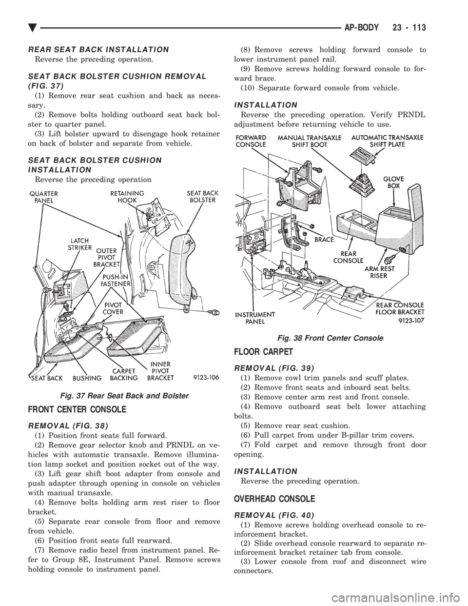
SEAT BACK BOLSTER CUSHION REMOVAL (FIG. 37)
(1) Remove rear seat cushion and back as neces-
sary. (2) Remove bolts holding outboard seat back bol-
ster to quarter panel. (3) Lift bolster upward to disengage hook retainer
on back of bolster and separate from vehicle.
SEAT BACK BOLSTER CUSHION INSTALLATION
Reverse the preceding operation
FRONT CENTER CONSOLE
REMOVAL (FIG. 38)
(1) Position front seats full forward.
(2) Remove gear selector knob and PRNDL on ve-
hicles with automatic transaxle. Remove illumina-
tion lamp socket and position socket out of the way. (3) Lift gear shift boot adapter from console and
push adapter through opening in console on vehicles
with manual transaxle. (4) Remove bolts holding arm rest riser to floor
bracket. (5) Separate rear console from floor and remove
from vehicle. (6) Position front seats full rearward.
(7) Remove radio bezel from instrument panel. Re-
fer to Group 8E, Instrument Panel. Remove screws
holding console to instrument panel. (8) Remove screws holding forward console to
lower instrument panel rail. (9) Remove screws holding forward console to for-
ward brace. (10) Separate forward console from vehicle.
INSTALLATION
Reverse the preceding operation. Verify PRNDL
adjustment before returning vehicle to use.
FLOOR CARPET
REMOVAL (FIG. 39)
(1) Remove cowl trim panels and scuff plates.
(2) Remove front seats and inboard seat belts.
(3) Remove center arm rest and front console.
(4) Remove outboard seat belt lower attaching
bolts. (5) Remove rear seat cushion.
(6) Pull carpet from under B-pillar trim covers.
(7) Fold carpet and remove through front door
opening.
INSTALLATION
Reverse the preceding operation.
OVERHEAD CONSOLE
REMOVAL (FIG. 40)
(1) Remove screws holding overhead console to re-
inforcement bracket. (2) Slide overhead console rearward to separate re-
inforcement bracket retainer tab from console. (3) Lower console from roof and disconnect wire
connectors.
Fig. 37 Rear Seat Back and Bolster
Fig. 38 Front Center Console
Ä AP-BODY 23 - 113
Page 2292 of 2438

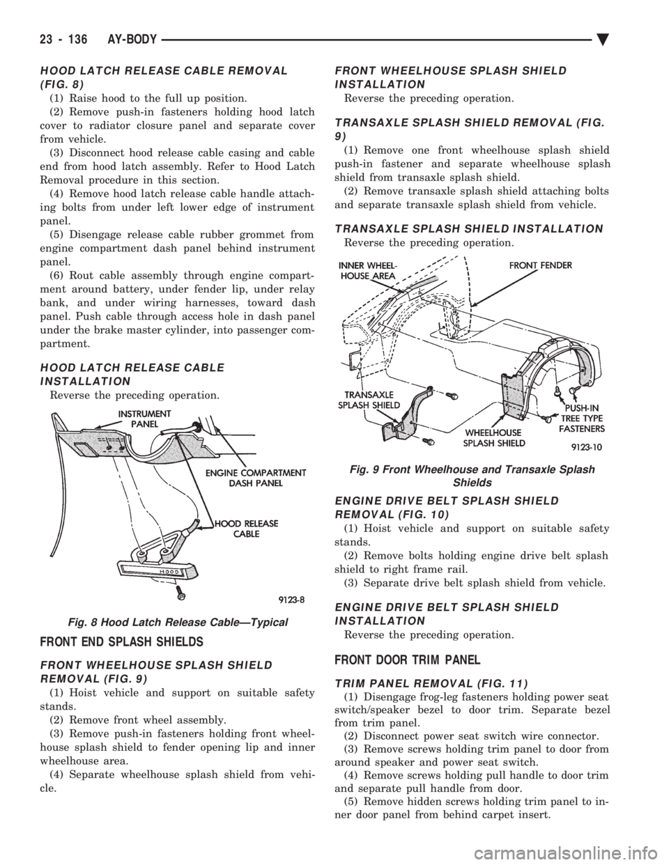
HOOD LATCH RELEASE CABLE REMOVAL (FIG. 8)
(1) Raise hood to the full up position.
(2) Remove push-in fasteners holding hood latch
cover to radiator closure panel and separate cover
from vehicle. (3) Disconnect hood release cable casing and cable
end from hood latch assembly. Refer to Hood Latch
Removal procedure in this section. (4) Remove hood latch release cable handle attach-
ing bolts from under left lower edge of instrument
panel. (5) Disengage release cable rubber grommet from
engine compartment dash panel behind instrument
panel. (6) Rout cable assembly through engine compart-
ment around battery, under fender lip, under relay
bank, and under wiring harnesses, toward dash
panel. Push cable through access hole in dash panel
under the brake master cylinder, into passenger com-
partment.
HOOD LATCH RELEASE CABLE INSTALLATION
Reverse the preceding operation.
FRONT END SPLASH SHIELDS
FRONT WHEELHOUSE SPLASH SHIELDREMOVAL (FIG. 9)
(1) Hoist vehicle and support on suitable safety
stands. (2) Remove front wheel assembly.
(3) Remove push-in fasteners holding front wheel-
house splash shield to fender opening lip and inner
wheelhouse area. (4) Separate wheelhouse splash shield from vehi-
cle.
FRONT WHEELHOUSE SPLASH SHIELD INSTALLATION
Reverse the preceding operation.
TRANSAXLE SPLASH SHIELD REMOVAL (FIG.9)
(1) Remove one front wheelhouse splash shield
push-in fastener and separate wheelhouse splash
shield from transaxle splash shield. (2) Remove transaxle splash shield attaching bolts
and separate transaxle splash shield from vehicle.
TRANSAXLE SPLASH SHIELD INSTALLATION
Reverse the preceding operation.
ENGINE DRIVE BELT SPLASH SHIELD REMOVAL (FIG. 10)
(1) Hoist vehicle and support on suitable safety
stands. (2) Remove bolts holding engine drive belt splash
shield to right frame rail. (3) Separate drive belt splash shield from vehicle.
ENGINE DRIVE BELT SPLASH SHIELDINSTALLATION
Reverse the preceding operation.
FRONT DOOR TRIM PANEL
TRIM PANEL REMOVAL (FIG. 11)
(1) Disengage frog-leg fasteners holding power seat
switch/speaker bezel to door trim. Separate bezel
from trim panel. (2) Disconnect power seat switch wire connector.
(3) Remove screws holding trim panel to door from
around speaker and power seat switch. (4) Remove screws holding pull handle to door trim
and separate pull handle from door. (5) Remove hidden screws holding trim panel to in-
ner door panel from behind carpet insert.
Fig. 8 Hood Latch Release CableÐTypical
Fig. 9 Front Wheelhouse and Transaxle Splash Shields
23 - 136 AY-BODY Ä
Page 2397 of 2438
ENGINE VACUUM SCHEMATICÐ3.0L, AUTOMATIC TRANSAXLE, ALL WITHOUT ABS AND AA, AG, AJ, AP, WITH ABS
Ä EMISSION CONTROL SYSTEMS 25 - 9
Page 2398 of 2438
ENGINE VACUUM SCHEMATICÐ3.0L, AUTOMATIC TRANSAXLE, AC BODY WITH ABS
25 - 10 EMISSION CONTROL SYSTEMS Ä
Page 2399 of 2438
ENGINE VACUUM SCHEMATICÐ3.0L, MANUAL TRANSAXLE, AG, AJ, AP
Ä EMISSION CONTROL SYSTEMS 25 - 11
Page 2417 of 2438

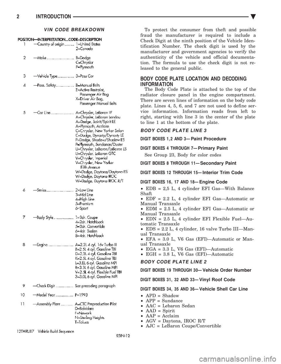
To protect the consumer from theft and possible
fraud the manufacturer is required to include a
Check Digit at the ninth position of the Vehicle Iden-
tification Number. The check digit is used by the
manufacturer and government agencies to verify the
authenticity of the vehicle and official documenta-
tion. The formula to use the check digit is not re-
leased to the general public.
BODY CODE PLATE LOCATION AND DECODING
INFORMATION
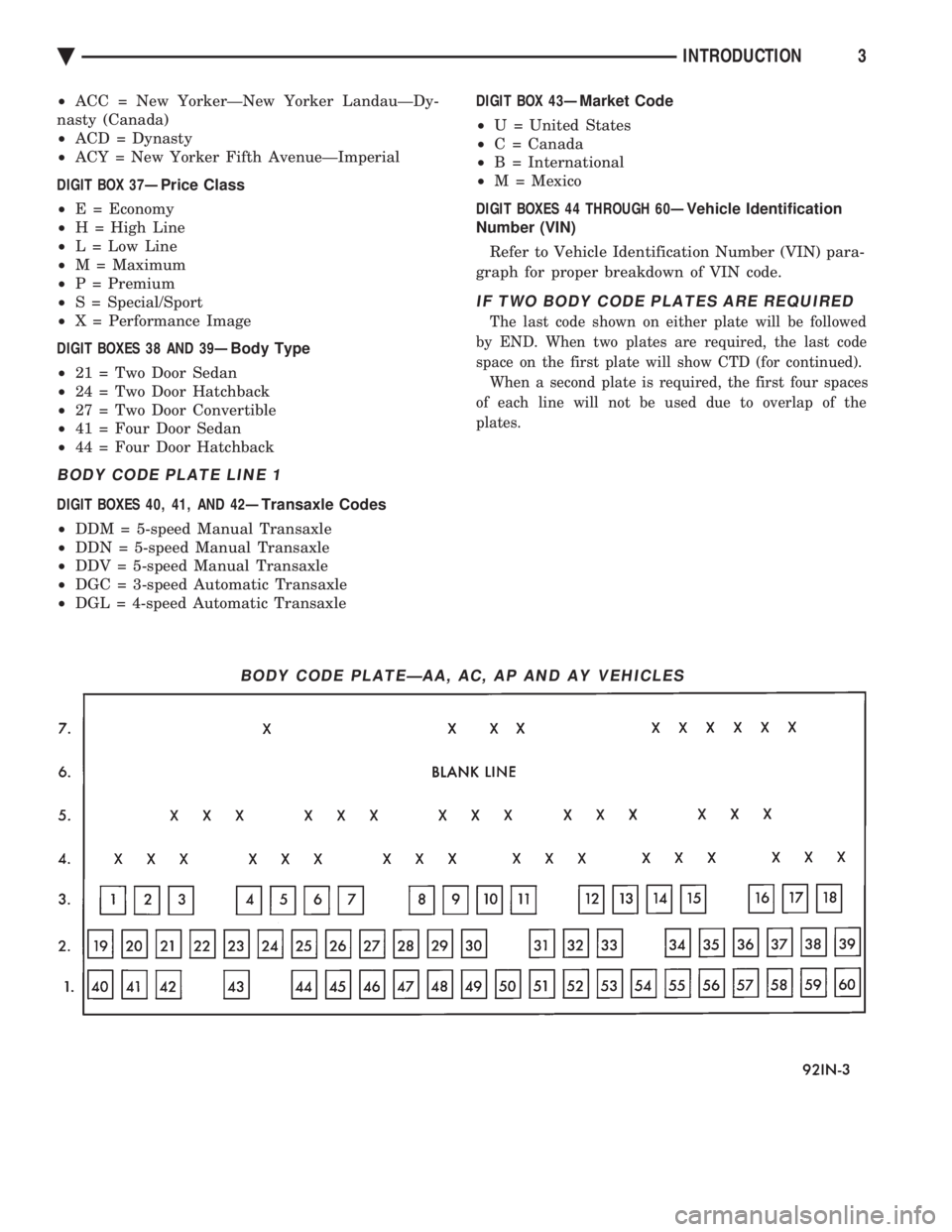
The Body Code Plate is attached to the top of the
radiator closure panel in the engine compartment.
There are seven lines of information on the body code
plate. Lines 4, 5, 6, and 7 are not used to define ser-
vice information. Information reads from left to
right, starting with line 3 in the center of the plate
to line 1 at the bottom of the plate.
BODY CODE PLATE LINE 3
DIGIT BOXES 1,2 AND 3Ð Paint Procedure
DIGIT BOXES 4 THROUGH 7Ð Primary Paint
See Group 23, Body for color codes
DIGIT BOXES 8 THROUGH 11Ð Secondary Paint
DIGIT BOXES 12 THROUGH 15Ð Interior Trim Code
DIGIT BOXES 16, 17 AND 18Ð Engine Code
² EDB = 2,5 L, 4 cylinder EFI GasÐWith Balance
Shaft
² EDF = 2.2 L, 4 cylinder EFI GasÐAutomatic or
Manual Transaxle
² EDM = 2.5 L, 4 cylinder EFI GasÐAutomatic or
Manual Transaxle
² EDN = 2.5 L, 4 cylinder EFI Flexible FuelÐAu-
tomatic Transaxle
² EDS = 2.2 L, 4 cylinder, 16 valve Turbo IIIÐMan-
ual Transaxle
² EFA = 3.0 L, V6 Gas (EFI)ÐAutomatic or Man-
ual Transaxle
² EGA = 3.3 L, V6 Gas (EFI)ÐAutomatic
² EGH = 3.8 L, V6 Gas (EFI)ÐAutomatic
BODY CODE PLATE LINE 2
DIGIT BOXES 19 THROUGH 30Ð Vehicle Order Number
DIGIT BOXES 31, 32 AND 33Ð Vinyl Roof Code
DIGIT BOXES 34, 35 AND 36Ð Vehicle Shell Car Line
² APD = Shadow
² APP = Sundance
² AAC = Lebaron Sedan
² AAD = Spirit
² AAP = Acclaim
² AGV = Daytona, IROC R/T
² AJC = LeBaron Coupe/Convertible
VIN CODE BREAKDOWN
2 INTRODUCTION Ä
Page 2418 of 2438

² ACC = New YorkerÐNew Yorker LandauÐDy-
nasty (Canada)
² ACD = Dynasty
² ACY = New Yorker Fifth AvenueÐImperial
DIGIT BOX 37Ð Price Class
² E = Economy
² H = High Line
² L = Low Line
² M = Maximum
² P = Premium
² S = Special/Sport
² X = Performance Image
DIGIT BOXES 38 AND 39Ð Body Type
² 21 = Two Door Sedan
² 24 = Two Door Hatchback
² 27 = Two Door Convertible
² 41 = Four Door Sedan
² 44 = Four Door Hatchback
BODY CODE PLATE LINE 1
DIGIT BOXES 40, 41, AND 42Ð Transaxle Codes
² DDM = 5-speed Manual Transaxle
² DDN = 5-speed Manual Transaxle
² DDV = 5-speed Manual Transaxle
² DGC = 3-speed Automatic Transaxle
² DGL = 4-speed Automatic Transaxle DIGIT BOX 43Ð
Market Code
² U = United States
² C = Canada
² B = International
² M = Mexico
DIGIT BOXES 44 THROUGH 60Ð Vehicle Identification
Number (VIN)
Refer to Vehicle Identification Number (VIN) para-
graph for proper breakdown of VIN code.
IF TWO BODY CODE PLATES ARE REQUIRED
The last code shown on either plate will be followed
by END. When two plates are required, the last code
space on the first plate will show CTD (for continued). When a second plate is required, the first four spaces
of each line will not be used due to overlap of the
plates.
BODY CODE PLATEÐAA, AC, AP AND AY VEHICLES
Ä INTRODUCTION3