1993 CHEVROLET PLYMOUTH ACCLAIM Transaxle
[x] Cancel search: TransaxlePage 2185 of 2438
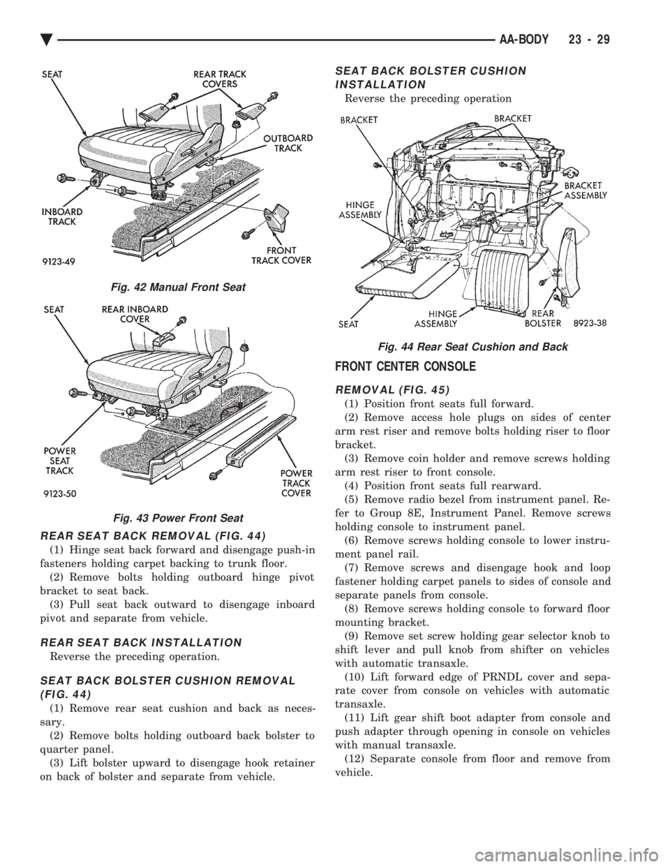
REAR SEAT BACK REMOVAL (FIG. 44)
(1) Hinge seat back forward and disengage push-in
fasteners holding carpet backing to trunk floor. (2) Remove bolts holding outboard hinge pivot
bracket to seat back. (3) Pull seat back outward to disengage inboard
pivot and separate from vehicle.
REAR SEAT BACK INSTALLATION
Reverse the preceding operation.
SEAT BACK BOLSTER CUSHION REMOVAL (FIG. 44)
(1) Remove rear seat cushion and back as neces-
sary. (2) Remove bolts holding outboard back bolster to
quarter panel. (3) Lift bolster upward to disengage hook retainer
on back of bolster and separate from vehicle.
SEAT BACK BOLSTER CUSHION INSTALLATION
Reverse the preceding operation
FRONT CENTER CONSOLE
REMOVAL (FIG. 45)
(1) Position front seats full forward.
(2) Remove access hole plugs on sides of center
arm rest riser and remove bolts holding riser to floor
bracket. (3) Remove coin holder and remove screws holding
arm rest riser to front console. (4) Position front seats full rearward.
(5) Remove radio bezel from instrument panel. Re-
fer to Group 8E, Instrument Panel. Remove screws
holding console to instrument panel. (6) Remove screws holding console to lower instru-
ment panel rail. (7) Remove screws and disengage hook and loop
fastener holding carpet panels to sides of console and
separate panels from console. (8) Remove screws holding console to forward floor
mounting bracket. (9) Remove set screw holding gear selector knob to
shift lever and pull knob from shifter on vehicles
with automatic transaxle. (10) Lift forward edge of PRNDL cover and sepa-
rate cover from console on vehicles with automatic
transaxle. (11) Lift gear shift boot adapter from console and
push adapter through opening in console on vehicles
with manual transaxle. (12) Separate console from floor and remove from
vehicle.
Fig. 42 Manual Front Seat
Fig. 43 Power Front Seat
Fig. 44 Rear Seat Cushion and Back
Ä AA-BODY 23 - 29
Page 2186 of 2438
INSTALLATION
Reverse the preceding operation. On vehicles with
automatic transaxle, verify gear selector indicator
adjustment before returning vehicle to use.
FLOOR CARPET
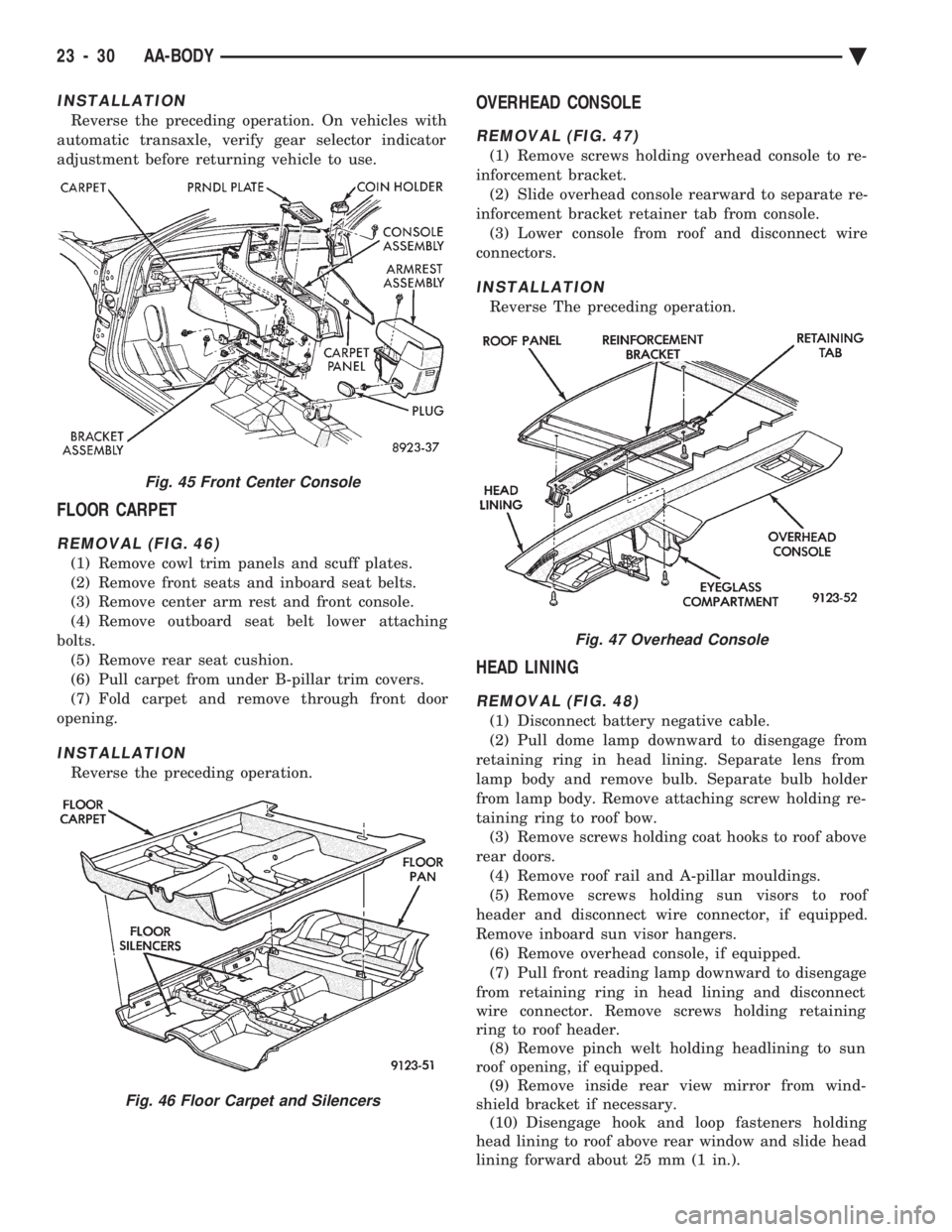
REMOVAL (FIG. 46)
(1) Remove cowl trim panels and scuff plates.
(2) Remove front seats and inboard seat belts.
(3) Remove center arm rest and front console.
(4) Remove outboard seat belt lower attaching
bolts. (5) Remove rear seat cushion.
(6) Pull carpet from under B-pillar trim covers.
(7) Fold carpet and remove through front door
opening.
INSTALLATION
Reverse the preceding operation.
OVERHEAD CONSOLE
REMOVAL (FIG. 47)
(1) Remove screws holding overhead console to re-
inforcement bracket. (2) Slide overhead console rearward to separate re-
inforcement bracket retainer tab from console. (3) Lower console from roof and disconnect wire
connectors.
INSTALLATION
Reverse The preceding operation.
HEAD LINING
REMOVAL (FIG. 48)
(1) Disconnect battery negative cable.
(2) Pull dome lamp downward to disengage from
retaining ring in head lining. Separate lens from
lamp body and remove bulb. Separate bulb holder
from lamp body. Remove attaching screw holding re-
taining ring to roof bow. (3) Remove screws holding coat hooks to roof above
rear doors. (4) Remove roof rail and A-pillar mouldings.
(5) Remove screws holding sun visors to roof
header and disconnect wire connector, if equipped.
Remove inboard sun visor hangers. (6) Remove overhead console, if equipped.
(7) Pull front reading lamp downward to disengage
from retaining ring in head lining and disconnect
wire connector. Remove screws holding retaining
ring to roof header. (8) Remove pinch welt holding headlining to sun
roof opening, if equipped. (9) Remove inside rear view mirror from wind-
shield bracket if necessary. (10) Disengage hook and loop fasteners holding
head lining to roof above rear window and slide head
lining forward about 25 mm (1 in.).
Fig. 45 Front Center Console
Fig. 46 Floor Carpet and Silencers
Fig. 47 Overhead Console
23 - 30 AA-BODY Ä
Page 2196 of 2438
panel. Push cable through access hole in dash panel
under the brake master cylinder, into passenger com-
partment.
INSTALLATION
Reverse the preceding operation.
FRONT END SPLASH SHIELDS
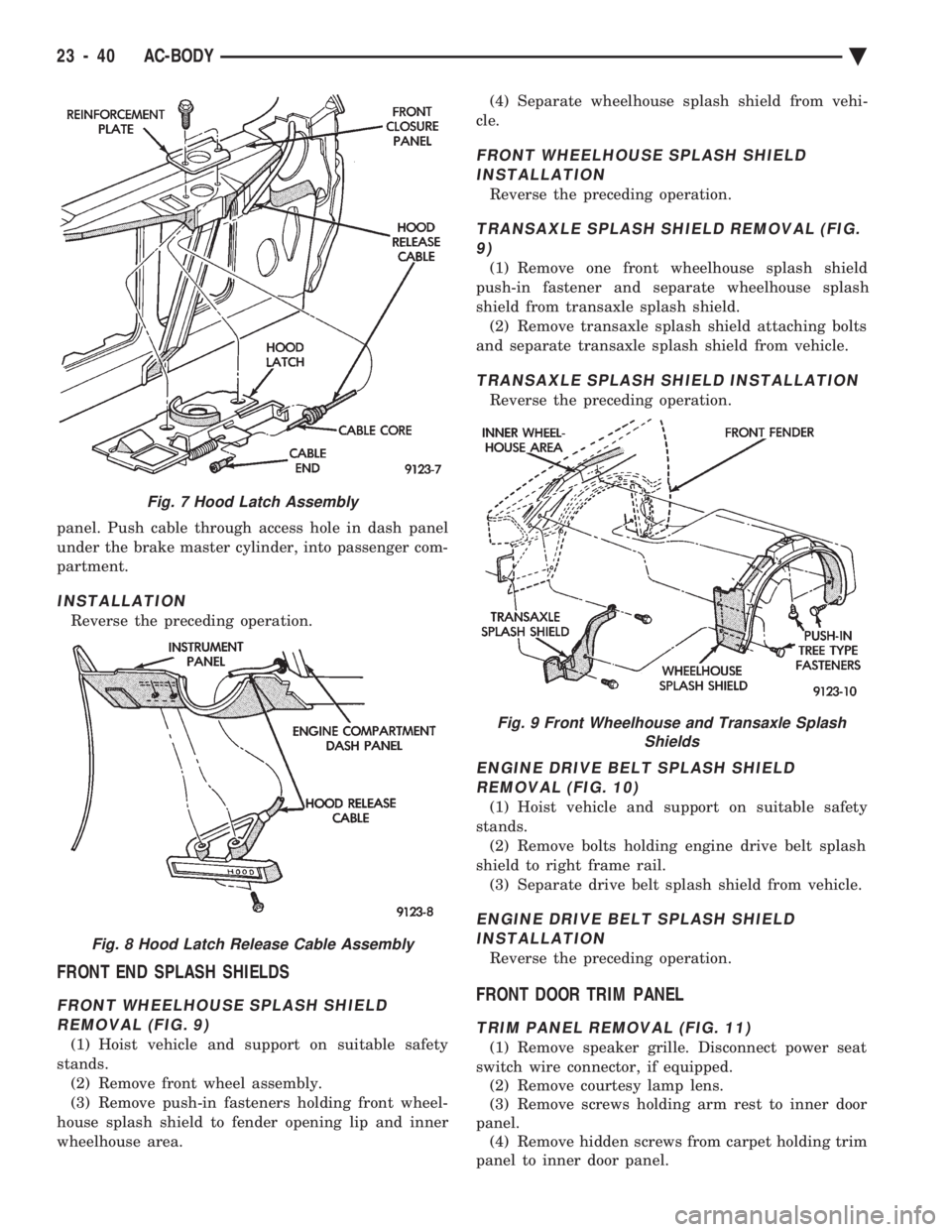
FRONT WHEELHOUSE SPLASH SHIELD REMOVAL (FIG. 9)
(1) Hoist vehicle and support on suitable safety
stands. (2) Remove front wheel assembly.
(3) Remove push-in fasteners holding front wheel-
house splash shield to fender opening lip and inner
wheelhouse area. (4) Separate wheelhouse splash shield from vehi-
cle.
FRONT WHEELHOUSE SPLASH SHIELD INSTALLATION
Reverse the preceding operation.
TRANSAXLE SPLASH SHIELD REMOVAL (FIG.9)
(1) Remove one front wheelhouse splash shield
push-in fastener and separate wheelhouse splash
shield from transaxle splash shield. (2) Remove transaxle splash shield attaching bolts
and separate transaxle splash shield from vehicle.
TRANSAXLE SPLASH SHIELD INSTALLATION
Reverse the preceding operation.
ENGINE DRIVE BELT SPLASH SHIELD REMOVAL (FIG. 10)
(1) Hoist vehicle and support on suitable safety
stands. (2) Remove bolts holding engine drive belt splash
shield to right frame rail. (3) Separate drive belt splash shield from vehicle.
ENGINE DRIVE BELT SPLASH SHIELDINSTALLATION
Reverse the preceding operation.
FRONT DOOR TRIM PANEL
TRIM PANEL REMOVAL (FIG. 11)
(1) Remove speaker grille. Disconnect power seat
switch wire connector, if equipped. (2) Remove courtesy lamp lens.
(3) Remove screws holding arm rest to inner door
panel. (4) Remove hidden screws from carpet holding trim
panel to inner door panel.
Fig. 7 Hood Latch Assembly
Fig. 8 Hood Latch Release Cable Assembly
Fig. 9 Front Wheelhouse and Transaxle Splash Shields
23 - 40 AC-BODY Ä
Page 2211 of 2438
(4) Separate wheelhouse splash shield from vehi-
cle.
INSTALLATION
Reverse the preceding operation.
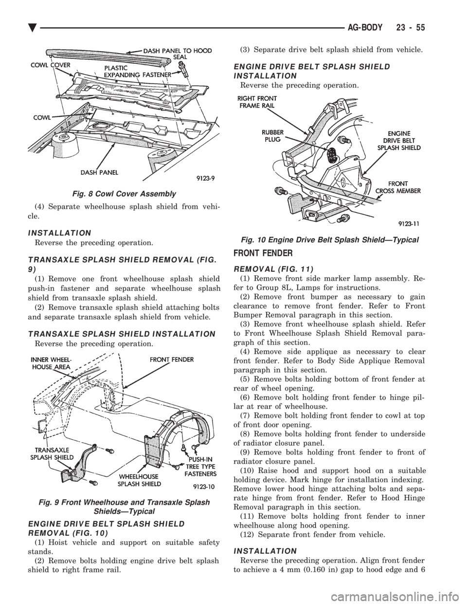
TRANSAXLE SPLASH SHIELD REMOVAL (FIG. 9)
(1) Remove one front wheelhouse splash shield
push-in fastener and separate wheelhouse splash
shield from transaxle splash shield. (2) Remove transaxle splash shield attaching bolts
and separate transaxle splash shield from vehicle.
TRANSAXLE SPLASH SHIELD INSTALLATION
Reverse the preceding operation.
ENGINE DRIVE BELT SPLASH SHIELD REMOVAL (FIG. 10)
(1) Hoist vehicle and support on suitable safety
stands. (2) Remove bolts holding engine drive belt splash
shield to right frame rail. (3) Separate drive belt splash shield from vehicle.
ENGINE DRIVE BELT SPLASH SHIELD
INSTALLATION
Reverse the preceding operation.
FRONT FENDER
REMOVAL (FIG. 11)
(1) Remove front side marker lamp assembly. Re-
fer to Group 8L, Lamps for instructions. (2) Remove front bumper as necessary to gain
clearance to remove front fender. Refer to Front
Bumper Removal paragraph in this section. (3) Remove front wheelhouse splash shield. Refer
to Front Wheelhouse Splash Shield Removal para-
graph of this section. (4) Remove side applique as necessary to clear
front fender. Refer to Body Side Applique Removal
paragraph in this section. (5) Remove bolts holding bottom of front fender at
rear of wheel opening. (6) Remove bolt holding front fender to hinge pil-
lar at rear of wheelhouse. (7) Remove bolt holding front fender to cowl at top
of front door opening. (8) Remove bolts holding front fender to underside
of radiator closure panel. (9) Remove bolts holding front fender to front of
radiator closure panel. (10) Raise hood and support hood on a suitable
holding device. Mark hinge for installation indexing.
Remove lower hood hinge attaching bolts and sepa-
rate hinge from front fender. Refer to Hood Hinge
Removal paragraph in this section. (11) Remove bolts holding front fender to inner
wheelhouse along hood opening. (12) Separate front fender from vehicle.
INSTALLATION
Reverse the preceding operation. Align front fender
to achiev ea4mm (0.160 in) gap to hood edge and 6
Fig. 8 Cowl Cover Assembly
Fig. 9 Front Wheelhouse and Transaxle Splash
ShieldsÐTypical
Fig. 10 Engine Drive Belt Splash ShieldÐTypical
Ä AG-BODY 23 - 55
Page 2220 of 2438
INSTALLATION
Reverse the preceding operation.
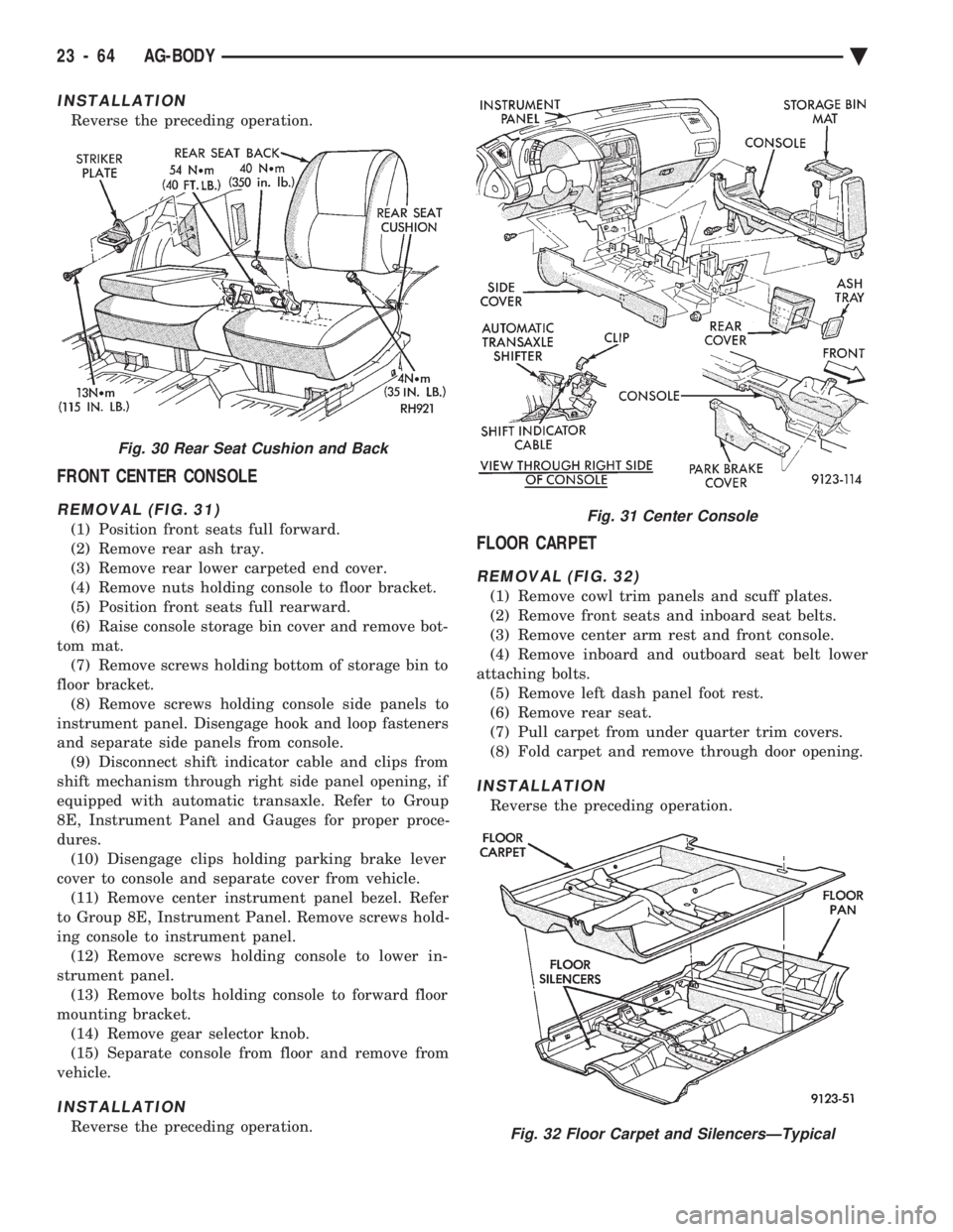
FRONT CENTER CONSOLE
REMOVAL (FIG. 31)
(1) Position front seats full forward.
(2) Remove rear ash tray.
(3) Remove rear lower carpeted end cover.
(4) Remove nuts holding console to floor bracket.
(5) Position front seats full rearward.
(6) Raise console storage bin cover and remove bot-
tom mat. (7) Remove screws holding bottom of storage bin to
floor bracket. (8) Remove screws holding console side panels to
instrument panel. Disengage hook and loop fasteners
and separate side panels from console. (9) Disconnect shift indicator cable and clips from
shift mechanism through right side panel opening, if
equipped with automatic transaxle. Refer to Group
8E, Instrument Panel and Gauges for proper proce-
dures. (10) Disengage clips holding parking brake lever
cover to console and separate cover from vehicle. (11) Remove center instrument panel bezel. Refer
to Group 8E, Instrument Panel. Remove screws hold-
ing console to instrument panel. (12) Remove screws holding console to lower in-
strument panel. (13) Remove bolts holding console to forward floor
mounting bracket. (14) Remove gear selector knob.
(15) Separate console from floor and remove from
vehicle.
INSTALLATION
Reverse the preceding operation.
FLOOR CARPET
REMOVAL (FIG. 32)
(1) Remove cowl trim panels and scuff plates.
(2) Remove front seats and inboard seat belts.
(3) Remove center arm rest and front console.
(4) Remove inboard and outboard seat belt lower
attaching bolts. (5) Remove left dash panel foot rest.
(6) Remove rear seat.
(7) Pull carpet from under quarter trim covers.
(8) Fold carpet and remove through door opening.
INSTALLATION
Reverse the preceding operation.
Fig. 30 Rear Seat Cushion and Back
Fig. 31 Center Console
Fig. 32 Floor Carpet and SilencersÐTypical
23 - 64 AG-BODY Ä
Page 2230 of 2438
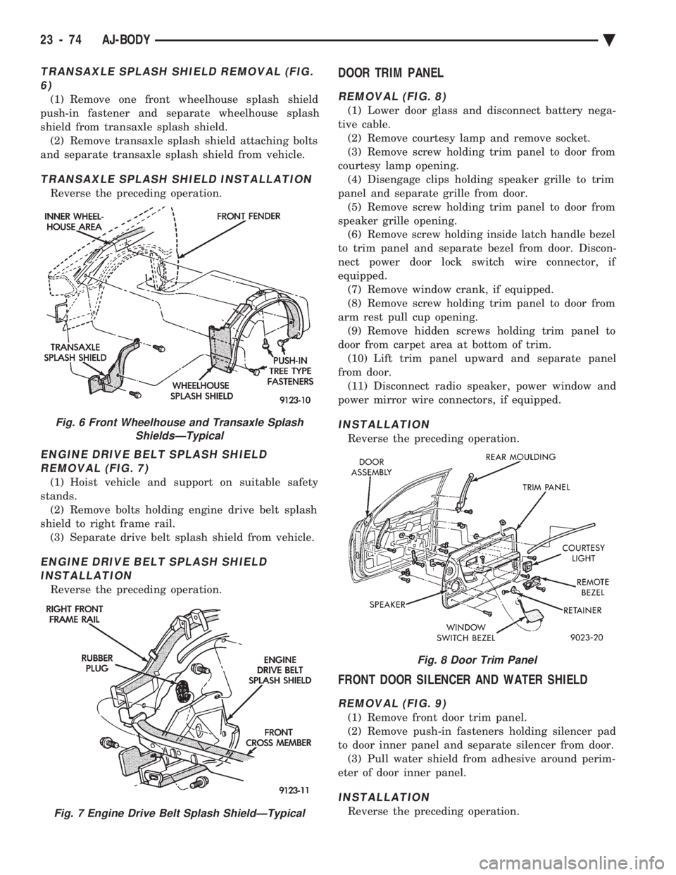
TRANSAXLE SPLASH SHIELD REMOVAL (FIG. 6)
(1) Remove one front wheelhouse splash shield
push-in fastener and separate wheelhouse splash
shield from transaxle splash shield. (2) Remove transaxle splash shield attaching bolts
and separate transaxle splash shield from vehicle.
TRANSAXLE SPLASH SHIELD INSTALLATION
Reverse the preceding operation.
ENGINE DRIVE BELT SPLASH SHIELD REMOVAL (FIG. 7)
(1) Hoist vehicle and support on suitable safety
stands. (2) Remove bolts holding engine drive belt splash
shield to right frame rail. (3) Separate drive belt splash shield from vehicle.
ENGINE DRIVE BELT SPLASH SHIELDINSTALLATION
Reverse the preceding operation.
DOOR TRIM PANEL
REMOVAL (FIG. 8)
(1) Lower door glass and disconnect battery nega-
tive cable. (2) Remove courtesy lamp and remove socket.
(3) Remove screw holding trim panel to door from
courtesy lamp opening. (4) Disengage clips holding speaker grille to trim
panel and separate grille from door. (5) Remove screw holding trim panel to door from
speaker grille opening. (6) Remove screw holding inside latch handle bezel
to trim panel and separate bezel from door. Discon-
nect power door lock switch wire connector, if
equipped. (7) Remove window crank, if equipped.
(8) Remove screw holding trim panel to door from
arm rest pull cup opening. (9) Remove hidden screws holding trim panel to
door from carpet area at bottom of trim. (10) Lift trim panel upward and separate panel
from door. (11) Disconnect radio speaker, power window and
power mirror wire connectors, if equipped.
INSTALLATION
Reverse the preceding operation.
FRONT DOOR SILENCER AND WATER SHIELD
REMOVAL (FIG. 9)
(1) Remove front door trim panel.
(2) Remove push-in fasteners holding silencer pad
to door inner panel and separate silencer from door. (3) Pull water shield from adhesive around perim-
eter of door inner panel.
INSTALLATION
Reverse the preceding operation.
Fig. 6 Front Wheelhouse and Transaxle Splash ShieldsÐTypical
Fig. 7 Engine Drive Belt Splash ShieldÐTypical
Fig. 8 Door Trim Panel
23 - 74 AJ-BODY Ä
Page 2236 of 2438
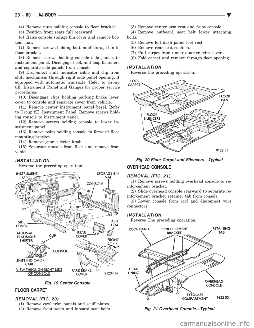
(4) Remove nuts holding console to floor bracket.
(5) Position front seats full rearward.
(6) Raise console storage bin cover and remove bot-
tom mat. (7) Remove screws holding bottom of storage bin to
floor bracket. (8) Remove screws holding console side panels to
instrument panel. Disengage hook and loop fasteners
and separate side panels from console. (9) Disconnect shift indicator cable and clip from
shift mechanism through right side panel opening, if
equipped with automatic transaxle. Refer to Group
8E, Instrument Panel and Gauges for proper service
procedures. (10) Disengage clips holding parking brake lever
cover to console and separate cover from vehicle. (11) Remove center instrument panel bezel. Refer
to Group 8E, Instrument Panel. Remove screws hold-
ing console to instrument panel. (12) Remove screws holding console to lower in-
strument panel. (13) Remove bolts holding console to forward floor
mounting bracket. (14) Remove gear selector knob.
(15) Separate console from floor and remove from
vehicle.
INSTALLATION
Reverse the preceding operation.
FLOOR CARPET
REMOVAL (FIG. 20)
(1) Remove cowl trim panels and scuff plates.
(2) Remove front seats and inboard seat belts. (3) Remove center arm rest and front console.
(4) Remove outboard seat belt lower attaching
bolts. (5) Remove left dash panel foot rest.
(6) Remove rear seat cushion.
(7) Pull carpet from under quarter trim covers.
(8) Fold carpet and remove through door opening.
INSTALLATION
Reverse the preceding operation.
OVERHEAD CONSOLE
REMOVAL (FIG. 21)
(1) Remove screws holding overhead console to re-
inforcement bracket. (2) Slide overhead console rearward to separate re-
inforcement bracket retainer tab from console. (3) Lower console from roof and disconnect wire
connectors.
INSTALLATION
Reverse The preceding operation.
Fig. 19 Center Console
Fig. 20 Floor Carpet and SilencersÐTypical
Fig. 21 Overhead ConsoleÐTypical
23 - 80 AJ-BODY Ä
Page 2255 of 2438
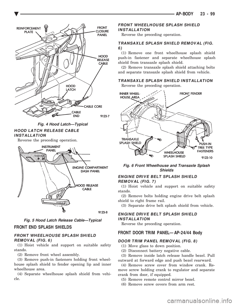
HOOD LATCH RELEASE CABLE INSTALLATION
Reverse the preceding operation.
FRONT END SPLASH SHIELDS
FRONT WHEELHOUSE SPLASH SHIELDREMOVAL (FIG. 6)
(1) Hoist vehicle and support on suitable safety
stands. (2) Remove front wheel assembly.
(3) Remove push-in fasteners holding front wheel-
house splash shield to fender opening lip and inner
wheelhouse area. (4) Separate wheelhouse splash shield from vehi-
cle.
FRONT WHEELHOUSE SPLASH SHIELD INSTALLATION
Reverse the preceding operation.
TRANSAXLE SPLASH SHIELD REMOVAL (FIG.6)
(1) Remove one front wheelhouse splash shield
push-in fastener and separate wheelhouse splash
shield from transaxle splash shield. (2) Remove transaxle splash shield attaching bolts
and separate transaxle splash shield from vehicle.
TRANSAXLE SPLASH SHIELD INSTALLATION
Reverse the preceding operation.
ENGINE DRIVE BELT SPLASH SHIELD REMOVAL (FIG. 7)
(1) Hoist vehicle and support on suitable safety
stands. (2) Remove bolts holding engine drive belt splash
shield to right frame rail. (3) Separate drive belt splash shield from vehicle.
ENGINE DRIVE BELT SPLASH SHIELDINSTALLATION
Reverse the preceding operation.
FRONT DOOR TRIM PANELÐAP-24/44 Body
DOOR TRIM PANEL REMOVAL (FIG. 8)
(1) Move glass to down position.
(2) Disconnect battery negative cable.
(3) Remove inside latch release handle bezel. Pull
outward at forward edge and push bezel rearward. (4) Remove screw cover from window crank. Re-
move screw holding crank to regulator and separate
crank from door, if equipped. (5) Remove remote control mirror bezel.
(6) Remove screw covers from arm rest.
Fig. 4 Hood LatchÐTypical
Fig. 5 Hood Latch Release CableÐTypical
Fig. 6 Front Wheelhouse and Transaxle Splash Shields
Ä AP-BODY 23 - 99