1993 CHEVROLET PLYMOUTH ACCLAIM stop start
[x] Cancel search: stop startPage 637 of 2438
WINDSHIELD WASHERS INDEX
page page
General Information ....................... 17
Washer Nozzle .......................... 19 Washer Reservoir Pump
................... 18
Washer Reservoirs ....................... 17
GENERAL INFORMATION
All models are equipped with electric operated
windshield washer pumps. The wash function can be accessed in the OFF po-
sition of the wiper control switch. Holding the wash
button depressed when the switch is in the OFF po-
sition will operate the wipers and washer motor
pump continuously until the washer button is re-
leased. Releasing the button will stop the washer
pump but the wipers will complete the current wipe
cycle. Then followed by an average of two more wipe
cycles ( 61) before the wipers park and the module
turns off. Whenever a windshield washer malfunction occurs,
first verify that the windshield washer wire harness
is properly connected to all connectors before starting
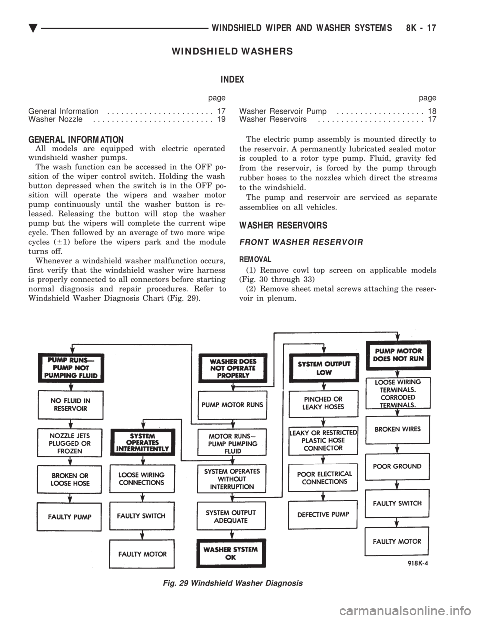
normal diagnosis and repair procedures. Refer to
Windshield Washer Diagnosis Chart (Fig. 29). The electric pump assembly is mounted directly to
the reservoir. A permanently lubricated sealed motor
is coupled to a rotor type pump. Fluid, gravity fed
from the reservoir, is forced by the pump through
rubber hoses to the nozzles which direct the streams
to the windshield. The pump and reservoir are serviced as separate
assemblies on all vehicles.
WASHER RESERVOIRS
FRONT WASHER RESERVOIR
REMOVAL
(1) Remove cowl top screen on applicable models
(Fig. 30 through 33) (2) Remove sheet metal screws attaching the reser-
voir in plenum.
Fig. 29 Windshield Washer Diagnosis
Ä WINDSHIELD WIPER AND WASHER SYSTEMS 8K - 17
Page 703 of 2438

VEHICLE THEFT SECURITY SYSTEM
CONTENTS
page page
GENERAL INFORMATION .................. 1
SECURITY SYSTEM DOOR SWITCH REPLACEMENT ........................ 2
SECURITY SYSTEM HOOD SWITCH REPLACEMENT ........................ 2 SYSTEM SELF-TESTS
.................... 1
VEHICLE THEFT SECURITY SYSTEM MODULE REPLACEMENT ........................ 2
WHAT WILL TRIGGER THE SYSTEM ........ 1
GENERAL INFORMATION
JUMP-STARTING, VEHICLE EQUIPPED
WITH THEFT SECURITY SYSTEM . After the
booster battery has been connected, the Theft System
must be turned OFF. Using the key, lock then un-
lock either front door. This turns the Theft System
OFF and the remainder of the Jump-Starting proce-
dure can be followed. If this procedure is not followed, the Theft System
electronics will prevent the engine from starting. If a new Powertrain Control Module is installed,
the engine has to be cranked 20 times before the
alarm system activated. This passive system is designed to protect against
whole vehicle theft. The system monitors vehicle
doors, hood, trunk key cylinder, and ignition action
for unauthorized operation. The alarm activates by
sounding the horn, flashing the park and tail lamps,
and providing an engine kill feature (Fig. 1). Passive arming occurs upon normal vehicle exit,
open door, lock with power locks, close door. The SET
lamp in the panel will flash for 15 seconds, indicat-
ing that arming is in progress. If no monitored sys-
tems are activated during this period, the system
will arm. If the hood or trunk key cylinder switches
are not sensed by the system. The SET lamp will re-
main lit during the arming process, although the sys-
tem will still arm. The system is to be considered as
an active armed system when using the Remote Key-
less Entry. If the SET lamp does not illuminate at all
upon door closing it indicates that the system is not
arming. Passive disarming occurs upon normal vehicle en-
try unlocking either door with the key, or unlocking
using the Remote Keyless transmitter. This disarm-
ing will also halt the alarm once it has been acti-
vated. Whenever the battery is disconnected and recon-
nected, the Vehicle Theft Security System enters
power up alarm mode which flashes the park and tail
lamps and prevents the engine from running. To exit
this mode, the system must be disarmed as men-
tioned above. A tamper alert exists to notify the driver that the
alarm had been activated, and the alarm has since
timed-out for more than 18 minutes. This alert con-
sists of 3 horn pulses when the vehicle is disarmed. The alarm system will not arm if the doors are
manually locked, providing a manual override of the
alarm.
WHAT WILL TRIGGER THE SYSTEM
One of the following actions will trigger the system
while it is armed. Without properly disarming sys-
tem, by using the key or the remote transmitter. (1) Opening the HOOD.
(2) Opening any DOOR.
(3) Removing the TRUNK KEY CYLINDER.
(4) Turning the IGNITION ON.
(5) The ignition switch can be turned to the acces-
sory position without triggering alarm system.
SYSTEM SELF-TESTS
A diagnostics mode is available in the system to
verify operation of all monitored switches or circuits.
To enter diagnostics, cycle the ignition key to the ac-
cessory position 3 times, leaving the key in this po-
sition. Upon entering diagnostics, the park and tail lamps
will begin flashing to verify their operation. In addi-
tion, the horn will sound twice to indicate that the
trunk key cylinder is in its proper position. Return-
ing the ignition to the OFF position will stop the
lamps from flashing while keeping the system in di-
agnostics. While in diagnostics mode, a horn pulse should oc-
cur at each of the following events indicating proper
operation: (1) Beginning with all doors closed, open then close
each door. The horn will sound when the door ajar
switch closes, and then again when the switch opens.
There must b e a 1 second delay between closing and
opening the switch. (2) Open, then close the hood. The horn will sound
when the hood is opened, and again when it is closed.
Ä VEHICLE THEFT SECURITY SYSTEM 8Q - 1
Page 931 of 2438
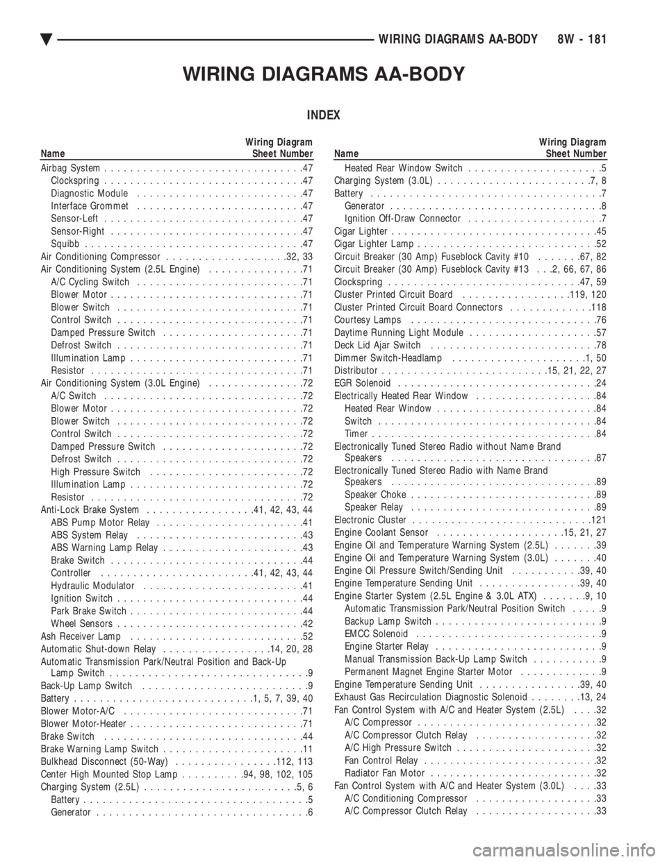
WIRING DIAGRAMS AA-BODY
INDEX
Wiring Diagram
Name Sheet Number
Airbag System ...............................47
Clockspring ...............................47
Diagnostic Module ..........................47
Interface Grommet ..........................47
Sensor-Left ...............................47
Sensor-Right ..............................47
Squibb ..................................47
Air Conditioning Compressor ...................32, 33
Air Conditioning System (2.5L Engine) ...............71
A/C Cycling Switch ..........................71
Blower Motor ..............................71
Blower Switch .............................71
Control Switch .............................71
Damped Pressure Switch ......................71
Defrost Switch .............................71
Illumination Lamp ...........................71
Resistor .................................71
Air Conditioning System (3.0L Engine) ...............72
A/C Switch ...............................72
Blower Motor ..............................72
Blower Switch .............................72
Control Switch .............................72
Damped Pressure Switch ......................72
Defrost Switch .............................72
High Pressure Switch ........................72
Illumination Lamp ...........................72
Resistor .................................72
Anti-Lock Brake System .................41, 42, 43, 44
ABS Pump Motor Relay .......................41
ABS System Relay ..........................43
ABS Warning Lamp Relay ......................43
Brake Switch ..............................44
Controller ....................... .41, 42, 43, 44
Hydraulic Modulator .........................41
Ignition Switch .............................44
Park Brake Switch ...........................44
Wheel Sensors .............................42
Ash Receiver Lamp ...........................52
Automatic Shut-down Relay .................14, 20, 28
Automatic Transmission Park/Neutral Position and Back-Up Lamp Switch ...............................9
Back-Up Lamp Switch ..........................9
Battery ............................1,5,7,39,40
Blower Motor-A/C ............................71
Blower Motor-Heater ...........................71
Brake Switch ...............................44
Brake Warning Lamp Switch ......................11
Bulkhead Disconnect (50-Way) ................112, 113
Center High Mounted Stop Lamp ..........94, 98, 102, 105
Charging System (2.5L) ........................5,6
Battery ...................................5
Generator .................................6Wiring Diagram
Name Sheet Number
Heated Rear Window Switch .....................5
Charging System (3.0L) ........................7,8
Battery ....................................7
Generator .................................8
Ignition Off-Draw Connector .....................7
Cigar Lighter ................................45
Cigar Lighter Lamp ............................52
Circuit Breaker (30 Amp) Fuseblock Cavity #10 .......67, 82
Circuit Breaker (30 Amp) Fuseblock Cavity #13 . . .2, 66, 67, 86
Clockspring ............................. .47, 59
Cluster Printed Circuit Board .................119, 120
Cluster Printed Circuit Board Connectors .............118
Courtesy Lamps .............................76
Daytime Running Light Module ....................57
Deck Lid Ajar Switch ..........................78
Dimmer Switch-Headlamp .....................1,50
Distributor ......................... .15, 21, 22, 27
EGR Solenoid ...............................24
Electrically Heated Rear Window ...................84
Heated Rear Window .........................84
Switch ..................................84
Timer ...................................84
Electronically Tuned Stereo Radio without Name Brand Speakers ................................87
Electronically Tuned Stereo Radio with Name Brand Speakers ................................89
Speaker Choke .............................89
Speaker Relay .............................89
Electronic Cluster ........................... .121
Engine Coolant Sensor ................... .15, 21, 27
Engine Oil and Temperature Warning System (2.5L) .......39
Engine Oil and Temperature Warning System (3.0L) .......40
Engine Oil Pressure Switch/Sending Unit ...........39, 40
Engine Temperature Sending Unit ................39, 40
Engine Starter System (2.5L Engine & 3.0L ATX) .......9,10
Automatic Transmission Park/Neutral Position Switch .....9
Backup Lamp Switch ..........................9
EMCC Solenoid .............................9
Engine Starter Relay ..........................9
Manual Transmission Back-Up Lamp Switch ...........9
Permanent Magnet Engine Starter Motor .............9
Engine Temperature Sending Unit ................39, 40
Exhaust Gas Recirculation Diagnostic Solenoid ........13, 24
Fan Control System with A/C and Heater System (2.5L) ....32
A/C Compressor ............................32
A/C Compressor Clutch Relay ...................32
A/C High Pressure Switch ......................32
Fan Control Relay ...........................32
Radiator Fan Motor ..........................32
Fan Control System with A/C and Heater System (3.0L) ....33
A/C Conditioning Compressor ...................33
A/C Compressor Clutch Relay ...................33
Ä WIRING DIAGRAMS AA-BODY 8W - 181
Page 933 of 2438
Wiring Diagram
Name Sheet Number
Illumination Lamp ...........................68
Resistor .................................68
Horn System ...............................65
Horn (Hi-Note) .............................65
Horn (Lo-Note) ............................65
Horn Relay ...............................65
Horn Switch ..............................65
Hydraulic Modulator (ABS) 41
Ignition Coil .......................... .14, 20, 29
Ignition Off-Draw Connector .....................5,7
Ignition Switch .............................4,11
Brake Warning Lamp Switch ....................11
Park Brake Switch ...........................11
Illuminated Entry .............................58
Illuminated Entry Module ......................58
Left Door Illuminated Entry Switch ................58
Right Door Illuminated Entry Switch ...............58
Illuminated Visor Vanity Mirror ....................73
Injector(s) ........................... .16, 17, 26
Instrument Panel Wiring to Left Body ...............123
Instrument Panel Wiring to Right Body ..............124
Instrument Panel to Multi-Function Switch ............116
Interface Grommet ............................47
Intermittent Wiper System .................... .63, 64
Intermittent Windshield Wiper Motor ...............64
Intermittent Wiper Control Module ................64
Multi-function Switch .........................63
Windshield Washer Low Fluid Level Sensor ...........63
Windshield Washer Pump Motor .................63
Key-In Switch ...............................46
Key-In Warning Chimes .........................45
Lamp Outage Module ........................ .115
Lamps A/C Lamps ...............................52
Ash Receiver Lamp ..........................52
Back-Up Lamps ............ .93, 94, 98, 102, 103, 105
Cargo Lamp ........................ .76, 96, 100
Center High Mounted Stop Lamp ........94, 98, 102, 105
Cigar Lighter Lamp ..........................52
Cluster Lamp ..............................77
Courtesy Lamps ............................76
Dome Lamp ..............................73
Fog Lamp-Left .............................56
Fog Lamp-Right ............................55
Front Reading Lamp .........................75
Glove Box Lamp ............................54
Halo Lamp ...............................54
Headlamp-Left .............................56
Headlamp Out Lamp .........................77
Headlamp-Right ............................55
Heater Lamp ..............................52
Illumination Lamp ..................... .68, 71, 72
Left Front Door Ajar Lamp .....................77
Left Rear Door Ajar Lamp ......................77
Left Side Marker Lamp ........................93
Left Tail/Stop and Turn Lamp ....................93
License Lamp ................... .93, 98, 102, 104Wiring Diagram
Name Sheet Number
Liftgate Ajar Lamp ..........................77
Low Washer Fluid Lamp .......................77
Park/Turn Lamp-Left .........................56
Park/Turn Lamp-Right ........................55
Radio Lamp ...............................52
Reading Lamps ............................75
Right Front Door Ajar Lamp ....................77
Right Rear Door Ajar Lamp .....................77
Seat Belt Warning Lamp .......................45
Side Marker Lamp-Left Front ....................56
Side Marker Lamp-Left Rear ...........93, 98, 102, 103
Side Marker Lamp-Right Front ...................55
Side Marker Lamp-Right Rear ..........94, 98, 102, 105
Stop Lamp Out Lamp ........................77
Tail Lamp Out Lamp .........................77
Tail/Stop Lamp-Left Rear ................... .93, 98
Tail/Stop Lamp-Right Rear .................. .94, 98
Tail/Stop and Turn Lamp-Left Rear .......93, 98, 102, 103
Tail/Stop and Turn Lamp-Right Rear ......94, 98, 102, 105
Transmission Range Indicator Lamp ...............76
Underhood Lamp ........................ .39, 40
Visor Vanity Mirror Lamp ......................73
Left Power Seat System ........................66
Center Switch .............................66
Front Switch ..............................66
Power Seat Motors ..........................66
Rear Switch ...............................66
License Lamp ..................... .93, 98, 102, 104
Lighter-Cigar ................................52
MAP Sensor .......................... .13, 19, 30
Message Center ..............................60
Traveler and Message Center ....................60
Mini Trip Computer ...........................60
Modules Airbag System Diagnostic Module .................47
Daytime Running Light Module ..................57
Illuminated Entry Module ......................58
Intermittent Wiper Control Module ................64
Lamp Outage Module ..................... .95, 99
Motors A/C-Heater Blower Motor ................... .71, 72
Fuel Pump Motor ...........................69
Heater Blower Motor .........................68
Idle Air Control Motor .................. .12, 18, 30
Intermittent Wiper Motor ......................64
Power Door Locks Motors .................. .85, 86
Power Seat Motors ..........................66
Power Window Motors .................... .81, 82
Radiator Fan Motor ...................... .32, 33
Starter Motor ............................9,10
Windshield Washer Pump Motor .................63
Name Brand Speaker Relay ......................89
Optical Horn Headlamp Dimmer Switch .............1,50
Overhead Console, Dome, Reading and Visor Vanity Lamps ..................... .73, 74, 75, 76
Ambient Temperature Sensor ....................75
Cargo Lamp ..............................76
Ä WIRING DIAGRAMS AA-BODY 8W - 183
Page 934 of 2438
Wiring Diagram
Name Sheet Number
Dome Lamp ..............................73
Front Reading Lamps .........................75
Illuminated Visor Vanity Lamps ..................73
Left Front Door Courtesy Lamp ..................76
Left Front Door Jamb Switch ....................75
Left Rear Door Courtesy Lamp ...................76
Left Rear Door Jamb Switch ....................76
Left Lamp Switch ...........................75
Overhead Console ...........................73
Right Front Door Courtesy Lamp .................76
Right Front Door Jamb Switch ...................74
Right Rear Door Courtesy Lamp ..................76
Right Rear Door Jamb Switch ...................73
Transmission Range Indicator Lamp ...............76
Power Assist System ..........................67
Power Door Interlock System ....................106
Power Door Lock Inhibit Relay ...................106
Power Door Lock System .................... .85, 86
Connectors and Door Lock Switch Function ........85, 86
Left Front Door Lock Motor .....................85
Left Front Door Lock Switch ....................85
Left Rear Door Lock Motor .....................85
Right Front Door Lock Motor ....................86
Right Front Door Lock Switch ...................86
Right Rear Door Lock Motor ....................86
Power Remote Heated Mirrors ..................79, 80
Heated Mirror .......................... .79, 80
Left Power Mirror ...........................79
Right Power Mirror ..........................80
Switch ..................................79
Switch Function ............................79
Powertrain Control Module (PCM) .....12, 13, 14, 15, 16, 17,
18, 19, 20, 21, 22, 23, 24, 25, 27, 28, 29, 30, 31, 59
Powertrain Control Module Flex Fuel Connector (2.5L Engine) ............................ .125
Powertrain Control Module Connector (2.5L) ...........108
Powertrain Control Module Connector (3.0L) .......109, 110
Power Window Connector and Switch Functions .........83
Power Window System ..................... .81, 82
Left Front Door Window Lift Master Switch ...........81
Left Front Window Regulator Motor ...............81
Left Rear Window Regulator Motor ................81
Left Rear Door Window Lift Switch ................81
Right Front Window Regulator Motor ...............82
Right Front Door Window Lift Switch ...............82
Right Rear Window Regulator Motor ...............82
Right Rear Door Window Lift Switch ...............82
Radiator Fan Motor ........................ .32, 33
Rear End Lighting (Chrysler/Dodge) with Lamp Outage ....................... .99, 100, 101, 102
Cargo Lamp ............................. .100
Center High Mounted Stop Lamp ................102
Lamp Outage Module .........................99
Left Back-Up Lamp ........................ .102
Left Side Marker Lamp ...................... .102
Left Tail/Stop and Turn Lamp ...................102
License Lamp ............................ .102Wiring Diagram
Name Sheet Number
Right Back-Up Lamp ....................... .102
Right Side Marker Lamp ..................... .102
Right Tail/Stop and Turn Lamp ..................102
Rear End Lighting (Chrysler/Dodge) without Lamp Outage ..................... .103, 104, 105
Center High Mounted Stop Lamp ................105
Left Back-Up Lamp ........................ .103
Left Side Marker Lamp ...................... .103
Left Tail/Stop and Turn Lamp ...................103
License Lamp ............................ .104
Right Back-Up Lamp ....................... .105
Right Side Marker Lamp ..................... .105
Right Tail/Stop and Turn Lamp ..................105
Rear End Lighting (Plymouth) with Lamp Outage ......................... .95, 96, 97, 98
Cargo Lamp ..............................96
Center High Mounted Stop Lamp .................98
Lamp Outage Module .........................95
Left Back-Up Lamp ..........................98
Left Side Marker Lamp ........................98
Left Tail/Stop and Turn Lamp ....................98
License Lamp .............................98
Right Back-Up Lamp .........................98
Right Side Marker Lamp .......................98
Right Tail/Stop and Turn Lamp ...................98
Rear End Lighting (Plymouth) without Lamp Outage ............................ .92, 93, 94
Center High Mounted Stop Lamp .................94
Left Back-Up Lamp ..........................93
Left Side Marker Lamp ........................93
Left Tail/Stop and Turn Lamp ....................93
License Lamp .............................93
Right Back-Up Lamp .........................94
Right Side Marker Lamp .......................94
Right Tail/Stop and Turn Lamp ...................94
Relay Bank ............................... .107
Relays ABS Pump Motor Relay .......................41
ABS System Relay ..........................43
ABS Warning Lamp Relay ......................43
A/C Compressor Clutch Relay .................32, 33
Automatic Shut-down Relay ...............14, 20, 28
Back-Up Lamp Relay .........................37
Engine Starter Relay ........................9,10
Fan Control Relay ....................... .32, 33
Fog Lamp Relay ............................48
Fuel Pump Relay ...........................70
Horn Relay ...............................65
Power Door Lock Inhibit Relay ..................106
Safety Shut-down Relay .......................35
Speaker Relay (NBS) .........................89
Time Delay Relay ...........................54
Seat Belt Warning System .................... .45, 46
Cigar Lighter ..............................45
Headlamp Switch Connector ....................46
Key-in Switch .............................46
Left Front Door Jamb Switch ....................46
8W - 184 WIRING DIAGRAMS AA-BODY Ä
Page 936 of 2438
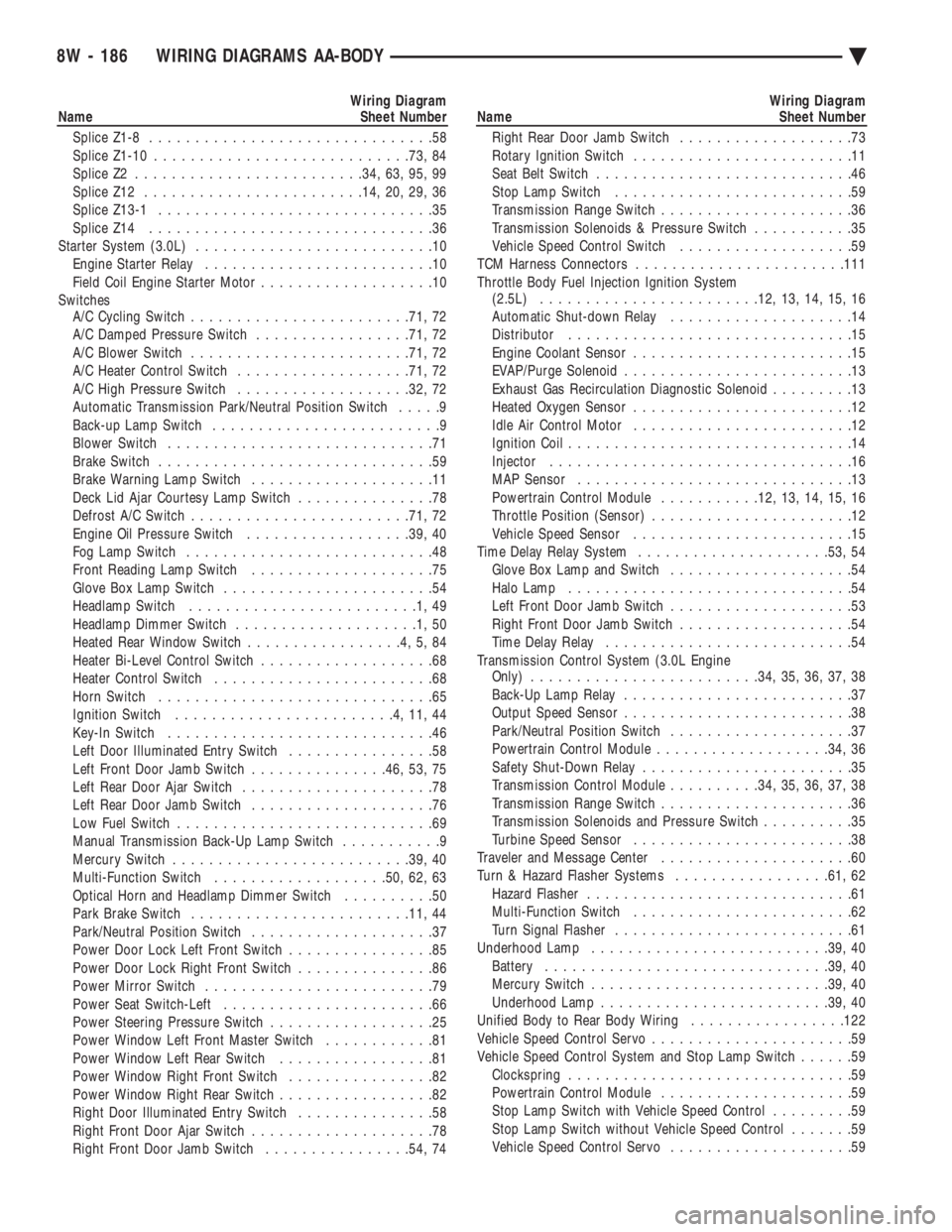
Wiring Diagram
Name Sheet Number
Splice Z1-8 ...............................58
Splice Z1-10 ........................... .73, 84
Splice Z2 ........................ .34, 63, 95, 99
Splice Z12 ....................... .14, 20, 29, 36
Splice Z13-1 ..............................35
Splice Z14 ...............................36
Starter System (3.0L) ..........................10
Engine Starter Relay .........................10
Field Coil Engine Starter Motor ...................10
Switches A/C Cycling Switch ....................... .71, 72
A/C Damped Pressure Switch .................71, 72
A/C Blower Switch ....................... .71, 72
A/C Heater Control Switch .................. .71, 72
A/C High Pressure Switch .................. .32, 72
Automatic Transmission Park/Neutral Position Switch .....9
Back-up Lamp Switch .........................9
Blower Switch .............................71
Brake Switch ..............................59
Brake Warning Lamp Switch ....................11
Deck Lid Ajar Courtesy Lamp Switch ...............78
Defrost A/C Switch ....................... .71, 72
Engine Oil Pressure Switch ..................39, 40
Fog Lamp Switch ...........................48
Front Reading Lamp Switch ....................75
Glove Box Lamp Switch .......................54
Headlamp Switch .........................1,49
Headlamp Dimmer Switch ....................1,50
Heated Rear Window Switch .................4,5,84
Heater Bi-Level Control Switch ...................68
Heater Control Switch ........................68
Horn Switch ..............................65
Ignition Switch ........................4,11,44
Key-In Switch .............................46
Left Door Illuminated Entry Switch ................58
Left Front Door Jamb Switch ...............46, 53, 75
Left Rear Door Ajar Switch .....................78
Left Rear Door Jamb Switch ....................76
Low Fuel Switch ............................69
Manual Transmission Back-Up Lamp Switch ...........9
Mercury Switch ......................... .39, 40
Multi-Function Switch .................. .50, 62, 63
Optical Horn and Headlamp Dimmer Switch ..........50
Park Brake Switch ....................... .11, 44
Park/Neutral Position Switch ....................37
Power Door Lock Left Front Switch ................85
Power Door Lock Right Front Switch ...............86
Power Mirror Switch .........................79
Power Seat Switch-Left .......................66
Power Steering Pressure Switch ..................25
Power Window Left Front Master Switch ............81
Power Window Left Rear Switch .................81
Power Window Right Front Switch ................82
Power Window Right Rear Switch .................82
Right Door Illuminated Entry Switch ...............58
Right Front Door Ajar Switch ....................78
Right Front Door Jamb Switch ................54, 74Wiring Diagram
Name Sheet Number
Right Rear Door Jamb Switch ...................73
Rotary Ignition Switch ........................11
Seat Belt Switch ............................46
Stop Lamp Switch ..........................59
Transmission Range Switch .....................36
Transmission Solenoids & Pressure Switch ...........35
Vehicle Speed Control Switch ...................59
TCM Harness Connectors ...................... .111
Throttle Body Fuel Injection Ignition System (2.5L) ....................... .12, 13, 14, 15, 16
Automatic Shut-down Relay ....................14
Distributor ...............................15
Engine Coolant Sensor ........................15
EVAP/Purge Solenoid .........................13
Exhaust Gas Recirculation Diagnostic Solenoid .........13
Heated Oxygen Sensor ........................12
Idle Air Control Motor ........................12
Ignition Coil ...............................14
Injector .................................16
MAP Sensor ..............................13
Powertrain Control Module ...........12, 13, 14, 15, 16
Throttle Position (Sensor) ......................12
Vehicle Speed Sensor ........................15
Time Delay Relay System .................... .53, 54
Glove Box Lamp and Switch ....................54
Halo Lamp ...............................54
Left Front Door Jamb Switch ....................53
Right Front Door Jamb Switch ...................54
Time Delay Relay ...........................54
Transmission Control System (3.0L Engine Only) ........................ .34, 35, 36, 37, 38
Back-Up Lamp Relay .........................37
Output Speed Sensor .........................38
Park/Neutral Position Switch ....................37
Powertrain Control Module .................. .34, 36
Safety Shut-Down Relay .......................35
Transmission Control Module ..........34, 35, 36, 37, 38
Transmission Range Switch .....................36
Transmission Solenoids and Pressure Switch ..........35
Turbine Speed Sensor ........................38
Traveler and Message Center .....................60
Turn & Hazard Flasher Systems .................61, 62
Hazard Flasher .............................61
Multi-Function Switch ........................62
Turn Signal Flasher ..........................61
Underhood Lamp ......................... .39, 40
Battery .............................. .39, 40
Mercury Switch ......................... .39, 40
Underhood Lamp ........................ .39, 40
Unified Body to Rear Body Wiring .................122
Vehicle Speed Control Servo ......................59
Vehicle Speed Control System and Stop Lamp Switch ......59
Clockspring ...............................59
Powertrain Control Module .....................59
Stop Lamp Switch with Vehicle Speed Control .........59
Stop Lamp Switch without Vehicle Speed Control .......59
Vehicle Speed Control Servo ....................59
8W - 186 WIRING DIAGRAMS AA-BODY Ä
Page 1068 of 2438
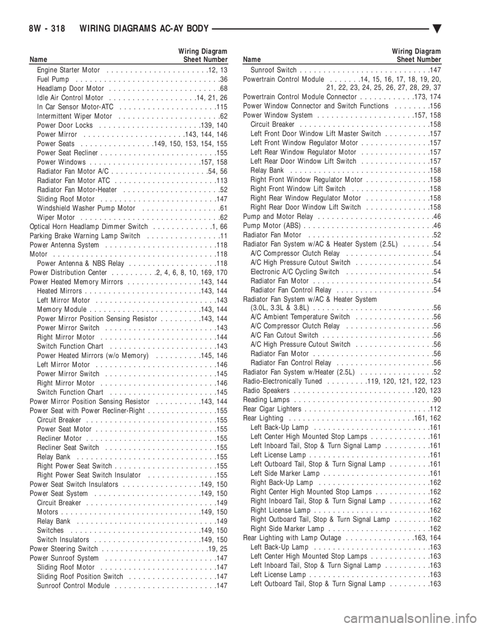
Wiring Diagram
Name Sheet Number
Engine Starter Motor ..................... .12, 13
Fuel Pump ...............................36
Headlamp Door Motor ........................68
Idle Air Control Motor .................. .14, 21, 26
In Car Sensor Motor-ATC .................... .115
Intermittent Wiper Motor ......................62
Power Door Locks ..................... .139, 140
Power Mirror ..................... .143, 144, 146
Power Seats ............... .149, 150, 153, 154, 155
Power Seat Recliner ........................ .155
Power Windows ....................... .157, 158
Radiator Fan Motor A/C .................... .54, 56
Radiator Fan Motor ATC ..................... .113
Radiator Fan Motor-Heater .....................52
Sliding Roof Motor ........................ .147
Windshield Washer Pump Motor .................61
Wiper Motor ..............................62
Optical Horn Headlamp Dimmer Switch .............1,66
Parking Brake Warning Lamp Switch ................11
Power Antenna System ....................... .118
Motor .................................. .118
Power Antenna & NBS Relay ...................118
Power Distribution Center ..........2,4,6,8,10, 169, 170
Power Heated Memory Mirrors ................143, 144
Heated Mirror s........................ .143, 144
Left Mirror Motor ......................... .143
Memory Module ....................... .143, 144
Power Mirror Position Sensing Resistor .........143, 144
Power Mirror Switch ....................... .143
Right Mirror Motor ........................ .144
Switch Function Chart ...................... .143
Power Heated Mirrors (w/o Memory) ..........145, 146
Left Mirror Motor ......................... .146
Power Mirror Switch ....................... .145
Right Mirror Motor ........................ .146
Switch Function Chart ...................... .145
Power Mirror Position Sensing Resistor ..........143, 144
Power Seat with Power Recliner-Right ...............155
Circuit Breaker ........................... .155
Power Seat Motor ......................... .155
Recliner Motor ........................... .155
Recliner Seat Switch ....................... .155
Relay Bank ............................. .155
Right Power Seat Switch ..................... .155
Right Power Seat Switch Insulator ...............155
Power Seat Switch Insulators .................149, 150
Power Seat System ...................... .149, 150
Circuit Breaker ........................... .149
Motors ............................. .149, 150
Relay Bank ............................. .149
Switches ........................... .149, 150
Switch Insulators ...................... .149, 150
Power Steering Switch ...................... .19, 25
Power Sunroof System ....................... .147
Sliding Roof Motor ........................ .147
Sliding Roof Position Switch ...................147
Sunroof Control Module ..................... .147Wiring Diagram
Name Sheet Number
Sunroof Switch ........................... .147
Powertrain Control Module .......14, 15, 16, 17, 18, 19, 20,
21, 22, 23, 24, 25, 26, 27, 28, 29, 37
Powertrain Control Module Connector ............173, 174
Power Window Connector and Switch Functions ........156
Power Window System .................... .157, 158
Circuit Breaker ........................... .158
Left Front Door Window Lift Master Switch ..........157
Left Front Window Regulator Motor ...............157
Left Rear Window Regulator Motor ...............157
Left Rear Door Window Lift Switch ...............157
Relay Bank ............................. .158
Right Front Window Regulator Motor ..............158
Right Front Window Lift Switch .................158
Right Rear Window Regulator Motor ..............158
Right Rear Door Window Lift Switch ..............158
Pump and Motor Relay .........................46
Pump Motor (ABS) ............................46
Radiator Fan Motor ...........................52
Radiator Fan System w/AC & Heater System (2.5L) .......54
A/C Compressor Clutch Relay ...................54
A/C High Pressure Cutout Switch .................54
Electronic A/C Cycling Switch ...................54
Radiator Fan Motor ..........................54
Radiator Fan Control Relay .....................54
Radiator Fan System w/AC & Heater System (3.0L, 3.3L & 3.8L) ..........................56
A/C Ambient Temperature Switch .................56
A/C Compressor Clutch Relay ...................56
A/C Fan Cutout Switch ........................56
A/C High Pressure Cutout Switch .................56
Radiator Fan Motor ..........................56
Radiator Fan Control Relay .....................56
Radiator Fan System w/Heater (2.5L) ................52
Radio-Electronically Tuned .........119, 120, 121, 122, 123
Radio Speakers ......................... .120, 123
Reading Lamps ..............................90
Rear Cigar Lighters .......................... .112
Rear Lighting .......................... .161, 162
Left Back-Up Lamp ........................ .161
Left Center High Mounted Stop Lamps .............161
Left Inboard Tail, Stop & Turn Signal Lamp ..........161
Left License Lamp ......................... .161
Left Outboard Tail, Stop & Turn Signal Lamp .........161
Left Side Marker Lamp ...................... .161
Right Back-Up Lamp ....................... .162
Right Center High Mounted Stop Lamps ............162
Right Inboard Tail, Stop & Turn Signal Lamp .........162
Right License Lamp ........................ .162
Right Outboard Tail, Stop & Turn Signal Lamp ........162
Right Side Marker Lamp ..................... .162
Rear Lighting with Lamp Outage ...............163, 164
Left Back-Up Lamp ........................ .163
Left Center High Mounted Stop Lamps .............163
Left Inboard Tail, Stop & Turn Signal Lamp ..........163
Left License Lamp ......................... .163
Left Outboard Tail, Stop & Turn Signal Lamp .........163
8W - 318 WIRING DIAGRAMS AC-AY BODY Ä
Page 1069 of 2438
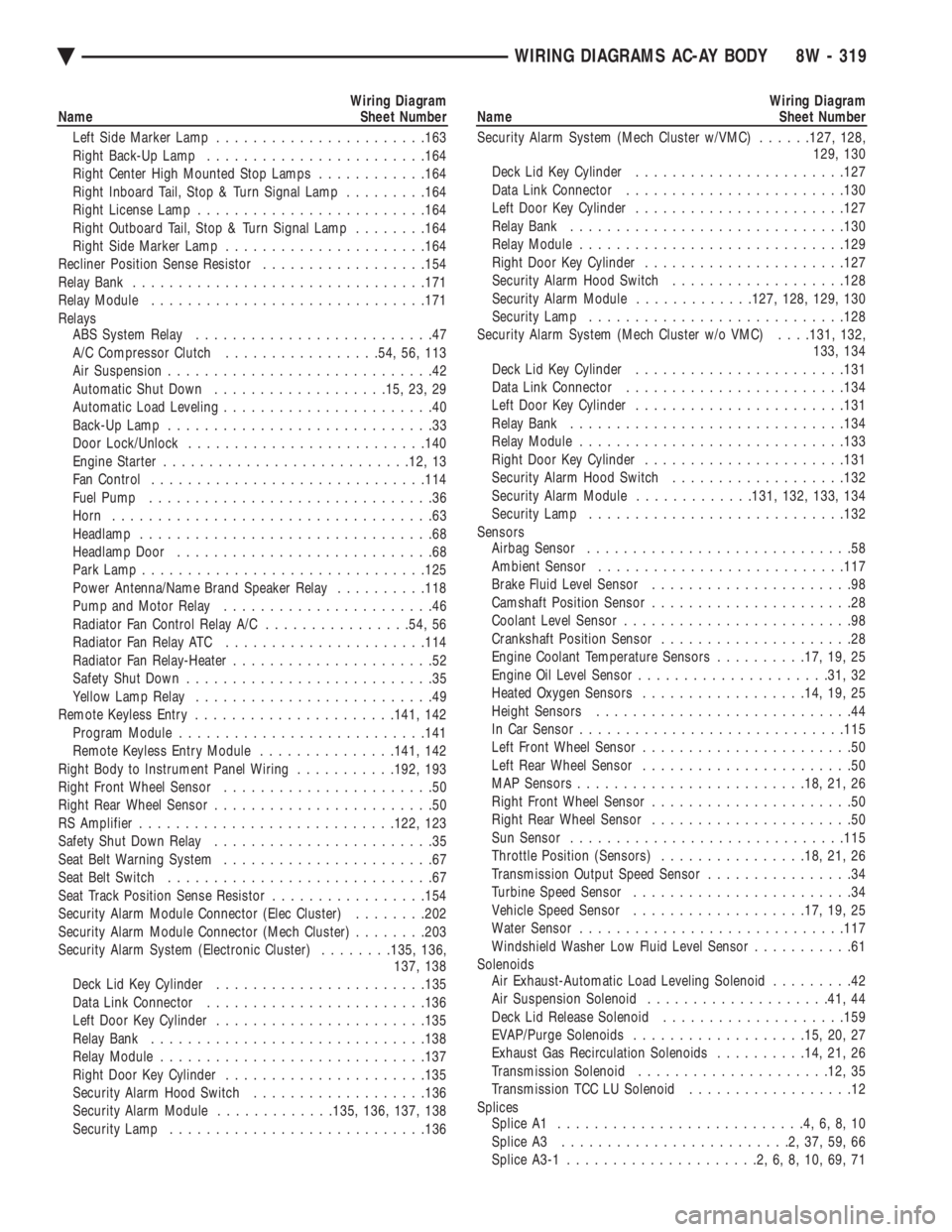
Wiring Diagram
Name Sheet Number
Left Side Marker Lamp ...................... .163
Right Back-Up Lamp ....................... .164
Right Center High Mounted Stop Lamps ............164
Right Inboard Tail, Stop & Turn Signal Lamp .........164
Right License Lamp ........................ .164
Right Outboard Tail, Stop & Turn Signal Lamp ........164
Right Side Marker Lamp ..................... .164
Recliner Position Sense Resistor ..................154
Relay Bank ............................... .171
Relay Module ............................. .171
Relays ABS System Relay ..........................47
A/C Compressor Clutch .................54, 56, 113
Air Suspension .............................42
Automatic Shut Down .................. .15, 23, 29
Automatic Load Leveling .......................40
Back-Up Lamp .............................33
Door Lock/Unlock ......................... .140
Engine Starter .......................... .12, 13
Fan Control ............................. .114
Fuel Pump ...............................36
Horn ...................................63
Headlamp ................................68
Headlamp Door ............................68
Park Lamp .............................. .125
Power Antenna/Name Brand Speaker Relay ..........118
Pump and Motor Relay .......................46
Radiator Fan Control Relay A/C ................54, 56
Radiator Fan Relay ATC ..................... .114
Radiator Fan Relay-Heater ......................52
Safety Shut Down ...........................35
Yellow Lamp Relay ..........................49
Remote Keyless Entry ..................... .141, 142
Program Module .......................... .141
Remote Keyless Entry Module ...............141, 142
Right Body to Instrument Panel Wiring ...........192, 193
Right Front Wheel Sensor .......................50
Right Rear Wheel Sensor ........................50
RS Amplifier ........................... .122, 123
Safety Shut Down Relay ........................35
Seat Belt Warning System .......................67
Seat Belt Switch .............................67
Seat Track Position Sense Resistor .................154
Security Alarm Module Connector (Elec Cluster) ........202
Security Alarm Module Connector (Mech Cluster) ........203
Security Alarm System (Electronic Cluster) ........135, 136,
137, 138
Deck Lid Key Cylinder ...................... .135
Data Link Connector ....................... .136
Left Door Key Cylinder ...................... .135
Relay Bank ............................. .138
Relay Module ............................ .137
Right Door Key Cylinder ..................... .135
Security Alarm Hood Switch ...................136
Security Alarm Module .............135, 136, 137, 138
Security Lamp ........................... .136Wiring Diagram
Name Sheet Number
Security Alarm System (Mech Cluster w/VMC) ......127, 128,
129, 130
Deck Lid Key Cylinder ...................... .127
Data Link Connector ....................... .130
Left Door Key Cylinder ...................... .127
Relay Bank ............................. .130
Relay Module ............................ .129
Right Door Key Cylinder ..................... .127
Security Alarm Hood Switch ...................128
Security Alarm Module .............127, 128, 129, 130
Security Lamp ........................... .128
Security Alarm System (Mech Cluster w/o VMC) . . . .131, 132,
133, 134
Deck Lid Key Cylinder ...................... .131
Data Link Connector ....................... .134
Left Door Key Cylinder ...................... .131
Relay Bank ............................. .134
Relay Module ............................ .133
Right Door Key Cylinder ..................... .131
Security Alarm Hood Switch ...................132
Security Alarm Module .............131, 132, 133, 134
Security Lamp ........................... .132
Sensors Airbag Sensor .............................58
Ambient Sensor .......................... .117
Brake Fluid Level Sensor ......................98
Camshaft Position Sensor ......................28
Coolant Level Sensor .........................98
Crankshaft Position Sensor .....................28
Engine Coolant Temperature Sensors ..........17, 19, 25
Engine Oil Level Sensor .................... .31, 32
Heated Oxygen Sensors ................. .14, 19, 25
Height Sensors ............................44
In Car Senso r............................ .115
Left Front Wheel Sensor .......................50
Left Rear Wheel Sensor .......................50
MAP Sensors ........................ .18, 21, 26
Right Front Wheel Sensor ......................50
Right Rear Wheel Sensor ......................50
Sun Sensor ............................. .115
Throttle Position (Sensors) ................18, 21, 26
Transmission Output Speed Sensor ................34
Turbine Speed Sensor ........................34
Vehicle Speed Sensor .................. .17, 19, 25
Water Sensor ............................ .117
Windshield Washer Low Fluid Level Sensor ...........61
Solenoids Air Exhaust-Automatic Load Leveling Solenoid .........42
Air Suspension Solenoid ................... .41, 44
Deck Lid Release Solenoid ................... .159
EVAP/Purge Solenoids .................. .15, 20, 27
Exhaust Gas Recirculation Solenoids ..........14, 21, 26
Transmission Solenoid .................... .12, 35
Transmission TCC LU Solenoid ..................12
Splices Splice A1 ...........................4,6,8,10
Splice A3 .........................2,37,59,66
Splice A3-1 .....................2,6,8,10,69,71
Ä WIRING DIAGRAMS AC-AY BODY 8W - 319