1993 CHEVROLET PLYMOUTH ACCLAIM stop start
[x] Cancel search: stop startPage 2058 of 2438
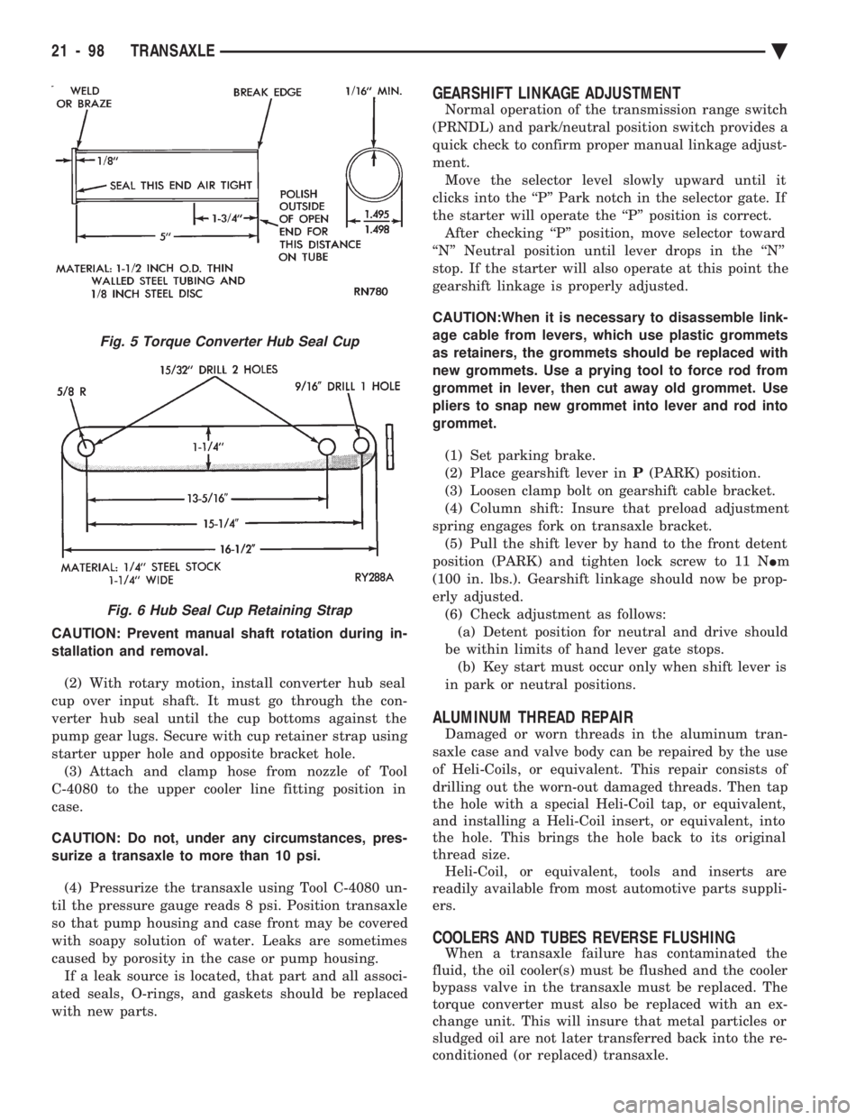
CAUTION: Prevent manual shaft rotation during in-
stallation and removal. (2) With rotary motion, install converter hub seal
cup over input shaft. It must go through the con-
verter hub seal until the cup bottoms against the
pump gear lugs. Secure with cup retainer strap using
starter upper hole and opposite bracket hole. (3) Attach and clamp hose from nozzle of Tool
C-4080 to the upper cooler line fitting position in
case.
CAUTION: Do not, under any circumstances, pres-
surize a transaxle to more than 10 psi.
(4) Pressurize the transaxle using Tool C-4080 un-
til the pressure gauge reads 8 psi. Position transaxle
so that pump housing and case front may be covered
with soapy solution of water. Leaks are sometimes
caused by porosity in the case or pump housing. If a leak source is located, that part and all associ-
ated seals, O-rings, and gaskets should be replaced
with new parts.
GEARSHIFT LINKAGE ADJUSTMENT
Normal operation of the transmission range switch
(PRNDL) and park/neutral position switch provides a
quick check to confirm proper manual linkage adjust-
ment. Move the selector level slowly upward until it
clicks into the ``P'' Park notch in the selector gate. If
the starter will operate the ``P'' position is correct. After checking ``P'' position, move selector toward
``N'' Neutral position until lever drops in the ``N''
stop. If the starter will also operate at this point the
gearshift linkage is properly adjusted.
CAUTION:When it is necessary to disassemble link-
age cable from levers, which use plastic grommets
as retainers, the grommets should be replaced with
new grommets. Use a prying tool to force rod from
grommet in lever, then cut away old grommet. Use
pliers to snap new grommet into lever and rod into
grommet.
(1) Set parking brake.
(2) Place gearshift lever in P(PARK) position.
(3) Loosen clamp bolt on gearshift cable bracket.
(4) Column shift: Insure that preload adjustment
spring engages fork on transaxle bracket. (5) Pull the shift lever by hand to the front detent
position (PARK) and tighten lock screw to 11 N Im
(100 in. lbs.). Gearshift linkage should now be prop-
erly adjusted. (6) Check adjustment as follows:(a) Detent position for neutral and drive should
be within limits of hand lever gate stops. (b) Key start must occur only when shift lever is
in park or neutral positions.
ALUMINUM THREAD REPAIR
Damaged or worn threads in the aluminum tran-
saxle case and valve body can be repaired by the use
of Heli-Coils, or equivalent. This repair consists of
drilling out the worn-out damaged threads. Then tap
the hole with a special Heli-Coil tap, or equivalent,
and installing a Heli-Coil insert, or equivalent, into
the hole. This brings the hole back to its original
thread size. Heli-Coil, or equivalent, tools and inserts are
readily available from most automotive parts suppli-
ers.
COOLERS AND TUBES REVERSE FLUSHING
When a transaxle failure has contaminated the
fluid, the oil cooler(s) must be flushed and the cooler
bypass valve in the transaxle must be replaced. The
torque converter must also be replaced with an ex-
change unit. This will insure that metal particles or
sludged oil are not later transferred back into the re-
conditioned (or replaced) transaxle.
Fig. 5 Torque Converter Hub Seal Cup
Fig. 6 Hub Seal Cup Retaining Strap
21 - 98 TRANSAXLE Ä
Page 2064 of 2438
(7) Press the number 5 on the DRB II scan tool
key pad (Adjustments). (8) Press the number 3 on the DRB II scan tool
key pad (Quick Learn). Then follow the instructions
on the DRB II scan tool screen.
PINION FACTOR PROCEDURE
The vehicle speed readings for the speedometer are
taken from the output speed sensor. Because of dif-
ferent tire sizes and final drive ratios, the transmis-
sion control module must be calibrated to reflect the
different combinations of equipment. A procedure has
been developed called Pinion Factor. It allows the
technician to set the transmission control module ini-
tial setting so that the speedometer readings will be
correct. Failure to perform this procedure will cause a ``No
Speedometer Operation'' condition. This procedure must be performed if the transmis-
sion control module has been replaced. To properly read or reset the Pinion Factor, it is
necessary to use a DRB II scan tool. Perform the fol-
lowing steps with the DRB II scan tool to read or re-
set the Pinion Factor: (1) Plug the DRB II scan tool into the blue CCD
Bus connector. The connector is located under the in-
strument panel on the drivers side of the vehicle. (2) Insert the 1993 DRB II scan tool cartridge into
the DRB II scan tool. (3) The red and green lights on the DRB II scan
tool will light up and then begin flashing. Wait until
the lights stop flashing before continuing with this
procedure. (4) Press the number 4 key (Select System) on the
DRB II scan tool key pad. Item number 4 will not ap-
pear on the DRB II scan tool screen unless you scroll
down. It is not necessary to scroll down to be able to
choose item 4. (5) Press the number 2 on the DRB II scan tool
key pad (Transmission). (6) Press the number 1 on the DRB II scan tool
key pad. Wait for the DRB II scan tool to perform the
following three tests before continuing (These tests
are done automatically by the DRB II scan tool).
² Bus Test
² Initialize
² Transmission Control Module Part Number
(7) Press the number 5 on the DRB II scan tool
key pad (Adjustments). (8) Press the number 2 on the DRB II scan tool
key pad (Pinion Factor). Then follow the instructions
on the DRB II scan tool screen.
TORQUE CONVERTER CLUTCH BREAK-IN
PROCEDURE
A torque converter clutch break-in program is be-
ing used on all models with a 41TE. This program
will properly condition the torque converter clutch. This will eliminate shudder during partial torque
converter clutch operation on a new torque converter.
If the torque converter is replaced, the new clutch
within the torque converter will require break-in.
The current break-in status stored in the transmis-
sion control module will have to be reset to the start
of break-in with the DRB II scan tool. If a new transmission control module is put on the
vehicle, the status will be at the start of break-in.
This status is acceptable regardless of the mileage on
the torque converter. No modification of the break-in
status is required. To properly service these vehicles, it is necessary to
use a DRB II scan tool to read or reset the break-in
status. Perform the following steps with the DRB II
scan tool to reset the break-in status: (1) Plug the DRB II scan tool into the blue CCD
Bus connector. The connector is located under the in-
strument panel on the drivers side of the vehicle. (2) Insert the 1993 DRB II scan tool cartridge into
the DRB II scan tool. (3) The red and green lights on the DRB II scan
tool will light up and then begin flashing. Wait until
the lights stop flashing before continuing with this
procedure. (4) Press the number 4 key (Select System) on the
DRB II scan tool key pad. Item number 4 will not ap-
pear on the DRB II scan tool screen unless you scroll
down. It is not necessary to scroll down to be able to
choose item 4. (5) Press the number 2 on the DRB II scan tool
key pad (Transmission). (6) Press the number 1 on the DRB II scan tool
key pad. Wait for the DRB II scan tool to perform the
following three tests before continuing (These tests
are done automatically by the DRB II scan tool).
² Bus Test
² Initialize
² Transmission Control Module Part Number
(7) Press the number 5 on the DRB II scan tool
key pad (Adjustments). (8) Press the number 1 on the DRB II scan tool
key pad (Reset LU Clutch). The DRB II scan tool will
display one of three screens. (a) LU Clutch Break-in Status: Start
(b) LU Clutch Break-in Status: In-progress
Press ENTER to Reset Break-in status (c) LU Clutch Break-in Status: CompletePress
ENTER to Reset Break-in status
If screen (a) appears, the transmission control mod-
ule is at the beginning of its break-in program. No
further action is required. If screen (b) appears, the transmission control mod-
ule is in the middle of a its break-in program. Press
the enter key on the DRB II scan tool key pad to re-
turn the status to the start of break-in.
21 - 104 TRANSAXLE Ä
Page 2159 of 2438
gage compartment. If light is visible through a nor-
mally sealed location, water could enter through the
opening.
PRESSURIZED LEAK TEST METHOD
When a water leak into the passenger compartment
can not be detected by water testing, pressurize the
passenger compartment and soap test exterior of the
vehicle. To pressurize the passenger compartment,
close all doors and windows, start engine, and set
heater control to high blower in HEAT position. If
engine can not be started, connect a charger to the
battery to assure adequate voltage to the blower. With
interior pressurized, apply dish detergent solution to
suspected leak area on the exterior of the vehicle.
Apply detergent solution with spray device or soft
bristle brush. If soap bubbles occur at a body seam,
joint, seal or gasket the leak entry point could be at
that location.
WIND NOISE
Wind noise is the result of most air leaks. Air leaks
can be caused by poor sealing, improper body compo-
nent alignment, body seam porosity, or missing plugs
in the engine compartment or door hinge pillar areas.
All body sealing points should be air tight in normal
driving conditions. Moving sealing surfaces will not
always seal air tight under all conditions. At times,
side glass, door, or convertible top seals will allow wind
noise to be noticed in the passenger compartment
during high cross-winds. Over compensating on door,
glass, or top adjustments to stop wind noise that occurs
under severe conditions, can cause premature seal
wear and excessive closing or latching effort. After a repair procedure has been performed, test vehicle to
verify leak has stopped before returning vehicle to use. Wind noise can also be caused by improperly fitted
exterior mouldings or body ornamentation. Loose
mouldings can flutter, creating a buzzing or chattering
noise. An open cavity or protruding edge can create
whistling or howling noise. Inspect the exterior of the
vehicle to verify that these conditions do not exist.
VISUAL INSPECTION BEFORE TESTS
Verify that floor and body plugs are in place, body
drains are clear and body components are aligned and
sealed. If component alignment or sealing is necessary,
refer to the appropriate section of this group for proper
procedures.
ROAD TESTING WIND NOISE
(1) Drive the vehicle to verify the general location of
the wind noise. (2) Apply 50 mm (2 in.) masking tape in 150 mm (6
in.) lengths along weatherstrips, weld seams or moul-
dings. After each length is applied drive vehicle. If
noise goes away after a piece of tape is applied, remove
tape, locate and repair defect.
POSSIBLE CAUSE OF WIND NOISE
² Mouldings standing away from body surface can
catch wind and whistle.
² Gaps in sealed areas behind overhanging body
flanges can cause wind rushing sounds.
² Misaligned movable components.
² Missing or improperly installed plugs in pillars.
² Weld burn through holes.
Ä BODY 23 - 3
Page 2310 of 2438
HEATER AND A/C PERFORMANCE TESTS
HEATER OUTPUT TEST
PRE-DIAGNOSTIC PREPARATIONS
Review Safety Precautions and Warnings before
performing the following procedures. Check the radiator coolant level, drive belt tension,
and engine vacuum line connections. Also check ra-
diator air flow and radiator fan operation. Start en-
gine and allow to warm up to normal operating
temperature.
WARNING: DO NOT REMOVE RADIATOR CAP
WHEN ENGINE IS HOT, PERSONAL INJURY CAN
RESULT.
If vehicle has been run recently, wait 15 minutes
before removing cap. Place a rag over the cap and
turn it to the first safety stop. Allow pressure to es-
cape through the overflow tube. When the system
stabilizes, remove the cap completely.
MAXIMUM HEATER OUTPUT: TEST AND ACTION
Engine coolant is provided to the heater system by
two 16 mm (5/8 inch inside diameter) heater hoses.
With engine idling at normal running temperature,
set the control to maximum heat, floor, and high
blower setting. Using a test thermometer, check the
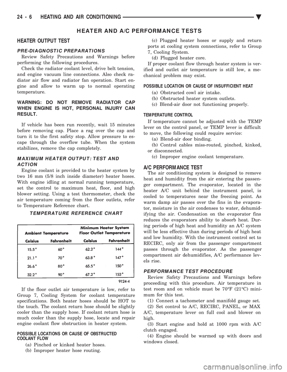
air temperature coming from the floor outlets, refer
to Temperature Reference chart.
If the floor outlet air temperature is low, refer to
Group 7, Cooling System for coolant temperature
specifications. Both heater hoses should be HOT to
the touch. The coolant return hose should be slightly
cooler than the supply hose. If coolant return hose is
much cooler than the supply hose, locate and repair
engine coolant flow obstruction in heater system.
POSSIBLE LOCATIONS OR CAUSE OF OBSTRUCTED
COOLANT FLOW
(a) Pinched or kinked heater hoses.
(b) Improper heater hose routing. (c) Plugged heater hoses or supply and return
ports at cooling system connections, refer to Group
7, Cooling System. (d) Plugged heater core.
If proper coolant flow through heater system is ver-
ified and outlet air temperature is still low, a me-
chanical problem may exist.
POSSIBLE LOCATION OR CAUSE OF INSUFFICIENT HEAT
(a) Obstructed cowl air intake.
(b) Obstructed heater system outlets.
(c) Blend-air door not functioning properly.
TEMPERATURE CONTROL If temperature cannot be adjusted with the TEMP
lever on the control panel, or TEMP lever is difficult
to move, the following could require service: (a) Blend-air door binding.
(b) Control cables miss-routed, pinched, kinked,
or disconnected. (c) Improper engine coolant temperature.A/C PERFORMANCE TEST
The air conditioning system is designed to remove
heat and humidity from the air entering the passen-
ger compartment. The evaporator, located in the
heater A/C unit behind the instrument panel, is
cooled to temperatures near the freezing point. As
warm damp air passes over the fins in the evapora-
tor, moisture in the air condenses to water, dehumid-
ifying the air. Condensation on the evaporator fins
reduces the evaporators ability to absorb heat. Dur-
ing periods of high heat and humidity an A/C system
will be less effective than during periods of high heat
and low humidity. With the instrument control set to
RECIRC, only air from the passenger compartment
passes through the evaporator. As the passenger
compartment air dehumidifies, A/C performance lev-
els rise.
PERFORMANCE TEST PROCEDURE
Review Safety Precautions and Warnings before
proceeding with this procedure. Air temperature in
test room and on vehicle must be 70ÉF (21ÉC) mini-
mum for this test. (1) Connect a tachometer and manifold gauge set.
(2) Set control to A/C, RECIRC, PANEL, or MAX
A/C, temperature lever on full cool and blower on
high. (3) Start engine and hold at 1000 rpm with A/C
clutch engaged. (4) Engine should be warmed up with doors and
windows closed.
TEMPERATURE REFERENCE CHART
24 - 6 HEATING AND AIR CONDITIONING Ä
Page 2316 of 2438
WARNING: REVIEW SAFETY PRECAUTIONS AND
WARNINGS BEFORE CHARGING THE REFRIGER-
ANT SYSTEM.
After the system has been tested for leaks and
evacuated, a refrigerant charge can be injected into
the system. (1) Connect manifold gauge set.
(2) Measure refrigerant (refer to capacities) and
heat to 52ÉC (125ÉF) with the charging station. Refer
to the instructions provided with the equipment be-
ing used.
REFRIGERANT CAPACITIES:
² Without Rear A/C = 907 g (32 oz.)
² With Rear A/C = 1219 g (43 oz.)
(3) Open the suction and discharge valves. Open
the charge valve to allow the heated refrigerant to
flow into the system. When the transfer of refriger-
ant has stopped, close the suction and discharge
valve. (4) If all of the refrigerant charge did not transfer
from the dispensing device, start engine and hold at
idle (1400 rpm). Set the A/C control to A/C, low
blower speed, and open windows. If the A/C compres-
sor does not engage, test the compressor clutch con-
trol circuit and correct any failure. Refer to Group
8W, Wiring Diagrams. (5) Open the suction valve to allow the remaining
refrigerant to transfer to the system.
WARNING: TAKE CARE NOT TO OPEN THE DIS-
CHARGE (HIGH-PRESSURE) VALVE AT THIS TIME.
(6) Close all valves and test the A/C system perfor-
mance. Refer to Heater and A/C Performance Tests
in this Group. (7) Disconnect the charging station or manifold
gauge set. Install the service port caps.
OIL LEVEL
It is important to have the correct amount of oil in
the A/C system to ensure proper lubrication of the
compressor. Too little oil will result in damage to the
compressor. Too much oil will reduce the cooling ca-
pacity of the system. The oil used in the compressor is a 500 SUS viscos-
ity, wax-free refrigerant oil. Only refrigerant oil of
the same type should be used to service the system.
Do not use any other oil. The oil container should be
kept tightly capped until it is ready for use, and then
tightly capped after use to prevent contamination
from dirt and moisture. Refrigerant oil will quickly
absorb any moisture it comes in contact with. It will not be necessary to check oil level in the
compressor or to add oil unless there has been an oil
loss. This may be due to a ruptured line, shaft seal leakage, leakage from the evaporator, condenser
leak, filter drier or loss of refrigerant due to a colli-
sion. Oil loss at a the leak point will be evident by
the presence of a wet, shiny surface around the leak.
REFRIGERANT OIL LEVEL CHECK
When an A/C system is assembled at the factory,
all components (except the compressor) are refriger-
ant oil free. After the system has been charged with
R-12 and operated, the oil in the compressor is dis-
persed through the lines and components. The evap-
orator, condenser, and filter-drier will retain a
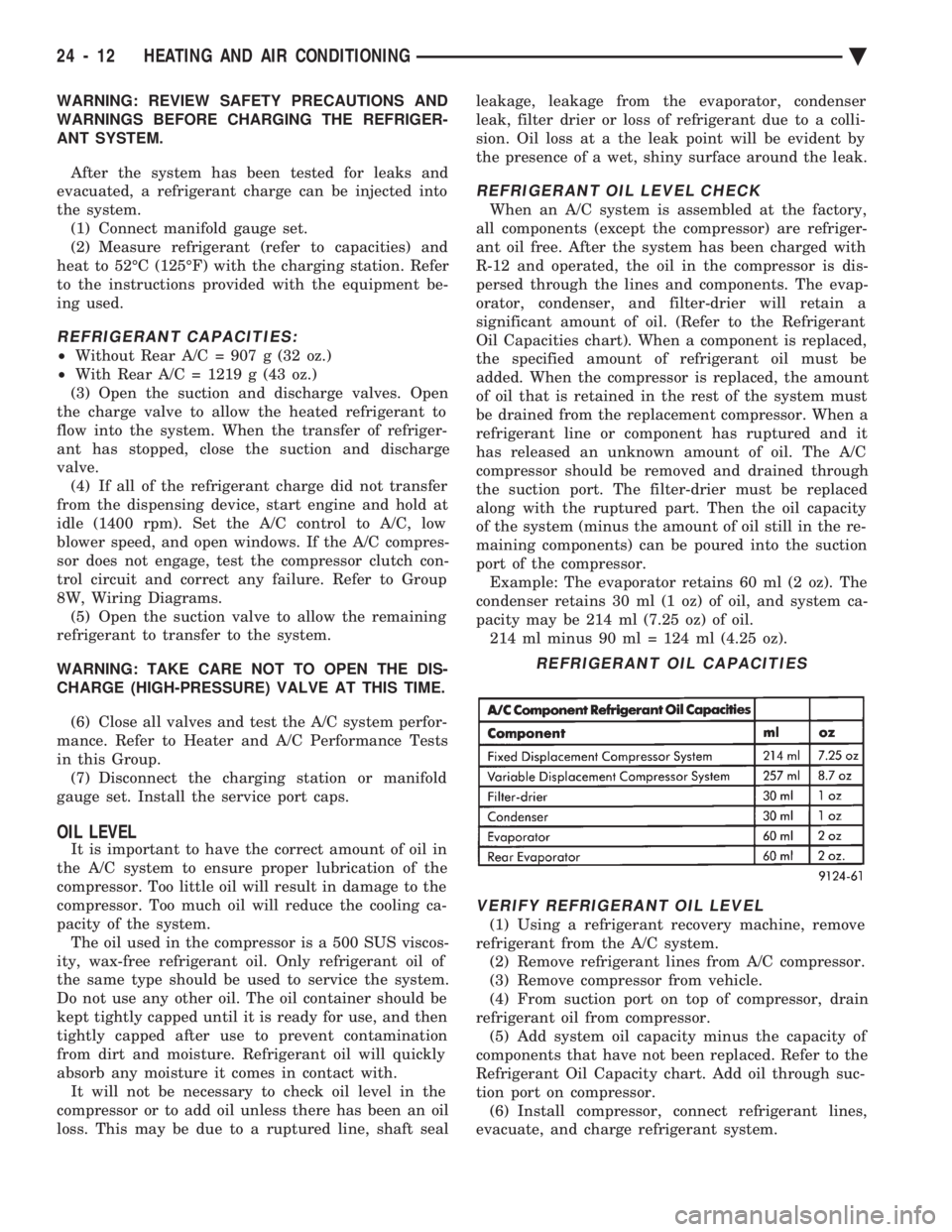
significant amount of oil. (Refer to the Refrigerant
Oil Capacities chart). When a component is replaced,
the specified amount of refrigerant oil must be
added. When the compressor is replaced, the amount
of oil that is retained in the rest of the system must
be drained from the replacement compressor. When a
refrigerant line or component has ruptured and it
has released an unknown amount of oil. The A/C
compressor should be removed and drained through
the suction port. The filter-drier must be replaced
along with the ruptured part. Then the oil capacity
of the system (minus the amount of oil still in the re-
maining components) can be poured into the suction
port of the compressor. Example: The evaporator retains 60 ml (2 oz). The
condenser retains 30 ml (1 oz) of oil, and system ca-
pacity may be 214 ml (7.25 oz) of oil. 214 ml minus 90 ml = 124 ml (4.25 oz).
VERIFY REFRIGERANT OIL LEVEL
(1) Using a refrigerant recovery machine, remove
refrigerant from the A/C system. (2) Remove refrigerant lines from A/C compressor.
(3) Remove compressor from vehicle.
(4) From suction port on top of compressor, drain
refrigerant oil from compressor. (5) Add system oil capacity minus the capacity of
components that have not been replaced. Refer to the
Refrigerant Oil Capacity chart. Add oil through suc-
tion port on compressor. (6) Install compressor, connect refrigerant lines,
evacuate, and charge refrigerant system.
REFRIGERANT OIL CAPACITIES
24 - 12 HEATING AND AIR CONDITIONING Ä
Page 2376 of 2438
NONÐCOMPUTER AIDED DIAGNOSTIC TESTS
Determine whether the operator complaint is due
to a system failure or improper operation of the ATC
system. The system will to go into a maximum heat
or cooling mode if the operator changes the tempera-
ture setting four or more degrees. Check the following:
² Coolant level
² Refrigerant charge
² Drive belt tension
² Radiator air flow
² Radiator fan operation
² Air suction of In-car Temperature Sensor/Aspirator
To check air suction of the Aspirator, place a small
piece of tissue paper over the Aspirator opening on
the instrument panel. This opening is located to the
right of the steering column. The tissue paper should
cling to the opening if system is functioning properly. Bring the engine to normal operating temperature
and proceed with Computer Aided Diagnostic Proce-
dures. Always test the entire system after each re-
pair has been performed.
COMPUTER AIDED DIAGNOSTIC TESTS
The ATC control has a computer capable of trou-
bleshooting the entire ATC system in approximately
60 seconds. The engine must be running and at nor-
mal operating temperature during the test to provide
hot coolant for the heater. During the ATC Diagnostic Test, the computer will
calibrate the Mode and Blend Door actuators.
CAUTION: Do not remove the actuators from the
heater-A/C unit assembly with power applied. Re-
moval should only be done with the Ignition OFF.
The actuators have no mechanical stops to limit the
travel. If the actuator rotates and is not connected
to the unit assembly, it will become un-calibrated.
The Diagnostic Test is capable of checking all elec-
trical signals between the ATC Control Module, ac-
tuators, sensors and blower control. The Diagnostic Test will display two types of Diag-
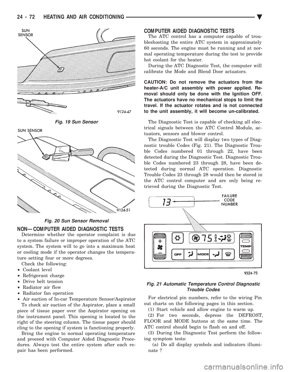
nostic trouble Codes (Fig. 21). The Diagnostic Trou-
ble Codes numbered 01 through 22, have been
detected during the Diagnostic Test. Diagnostic Trou-
ble Codes numbered 23 through 28, have been de-
tected during normal ATC operation. Diagnostic
Trouble Codes 23 through 28 would then be stored in
the ATC control computer and are only being re-
trieved during the Diagnostic Test.
For electrical pin numbers, refer to the wiring Pin
out charts on the following pages in this section. (1) Start vehicle and allow engine to warm up.
(2) For two seconds, depress the DEFROST,
FLOOR and MODE buttons at the same time. The
ATC control should begin to flash on and off. (3) During the Diagnostic Test perform the follow-
ing symptom tests: (a) Do all display symbols and indicators illumi-
nate ?
Fig. 19 Sun Sensor
Fig. 20 Sun Sensor Removal
Fig. 21 Automatic Temperature Control Diagnostic Trouble Codes
24 - 72 HEATING AND AIR CONDITIONING Ä
Page 2377 of 2438
(b) Does the blower motor operate at its highest
speed ? (c) Feel the outlet temperature. Does it get hot
and then cycle cold ? (d) Does the air flow switch from DEFROST out-
lets and then cycle to PANEL outlets?
If you can answer NO to any of these questions,
proceed to step 4, otherwise proceed to step 5. (4) If you answered NO to:
SYMPTOM A
The display symbols and indicators do not illumi-
nate. Diagnostic Trouble Codes are not displayed.
TEST
After self-diagnostic test is complete, select a mode
that will display the malfunction.
ACTION
If the ATC system operates properly, and the dis-
play does not, replace ATC control panel computer.
SYMPTOM B
The blower motor does not operate.
CAUTION: Stay clear of blower motor and power
module (PM) heat sink. Do not run system for more
than 10 minutes with PM removed from A/C unit.
TEST Check all power module and blower motor connec-
tions. Use a voltmeter to test for 12 volts (ignition)
at both ends of the fuse with ignition ON. If fuse is
good, test the green wire at the blower motor connec-
tor for 12 volts (ignition) to body ground. Turn ignition to the ON position.
With the blower motor still connected, check for 12
volts to body ground on the black/tan wire of the
blower motor two way connector. Check for 12 volts at the Power Module pin #4
(BK/TN). Check for continuity from the Power Module pin
#3 (BK) to chassis ground. Replace the Power Module.
ACTION If 12 volts is not detected, repair feed circuit. Refer
to the Front Wheel Drive Car-Wiring Diagrams Ser-
vice Manual. If 12 volts is not detected, repair wires of the
blower motor or replace the blower motor. If 12 volts is not present, repair wire from the
blower motor connector to the Power Module. If circuit is open, repair ground circuit of the Power
Module. Replace the Power Module (power transistor open).
SYMPTOM C
The outlet air temperature does not become hot
and then cycle to cold during self-test operation. Di-
agnostic Trouble Codes are not displayed.
TEST/ACTION
Make sure the blend-air door is properly attached
to the actuator. If cold air is not discharged from the outlets, check
the base A/C refrigerant system. Make sure heating operation works correctly, (wa-
ter level, thermostat, heater hoses, heater core, etc.).
SYMPTOM D
Air does not flow from DEFROST outlets and then
cycle to PANEL outlets during self-test operation.
TEST/ACTION Check linkages from the mode door actuator for
binding. Check for proper door travel in the unit.
(5) The computer will do one of two things:
² Will return to the control settings that were se-
lected before the Diagnostic Test was started. This
means the test is over. If Diagnostic Trouble Codes
did not occur, and answers to questions (a), (b), (c),
and (d) were YES, the entire system is operating cor-
rectly.
² The blower motor will stop and the computer will
flash a Diagnostic Trouble Code number from 01
through 28. Record the number and then depress the
PANEL button to advance to the next test. If the
ATC control flashes one or more codes 23 to 28, the
digits on the display will flash alternating Zeros. If
you do nothing, these codes will remain stored within
the ATC control computer. After all repairs have
been made erase fault codes. Refer to Erasing Diag-
nostic Trouble Codes 23 through 28 from ATC Con-
trol in this section. Repair all Diagnostic Trouble Codes in the order
that they have been indicated, and then retest the
system. If any blend door test fails, all remaining
blend door tests will be skipped. IF any mode door
tests fail, all remaining mode door tests will be
skipped. Diagnostic Test can be stopped at any time by de-
pressing any button other than PANEL.
DIAGNOSTIC TROUBLE CODE DEFINITIONS
Non-computer aided diagnostics should be per-
formed first. Hood of vehicle should be closed during
the diagnostic test to keep engine heat from effecting
the ambient temperature sensor. Also refer to the wiring Pin out charts.
² DIAGNOSTIC TROUBLE CODE 1
Involves the wiring or the ATC control head.
² DIAGNOSTIC TROUBLE CODES 2, 13, 14, 15,
20, and 23
Ä HEATING AND AIR CONDITIONING 24 - 73