1993 CHEVROLET PLYMOUTH ACCLAIM AA body
[x] Cancel search: AA bodyPage 52 of 2438

DRIVETRAIN INDEX
page page
Automatic Transaxle ...................... 16
Automatic Transaxle Floor Shift .............. 16
Clutch and Gearshift Linkage ............... 16
Drive Shaft Cv and Tripod Joint Boots ........ 17 Front Wheel Bearings
..................... 17
Manual Transaxle ........................ 16
Tires .................................. 17
CLUTCH AND GEARSHIFT LINKAGE
If the clutch or gearshift begins to operate with dif-
ficulty, squeak or grunt, the cables and linkage
should be lubricated before service replacement is
performed. For proper lubrication and service proce-
dures refer to Group 6, Clutch, or Group 21, Manual
Transaxle.
MANUAL TRANSAXLE
The manual transaxle should be inspected for oil
leaks and proper oil level when other under vehicle
service is performed. To inspect the transaxle oil
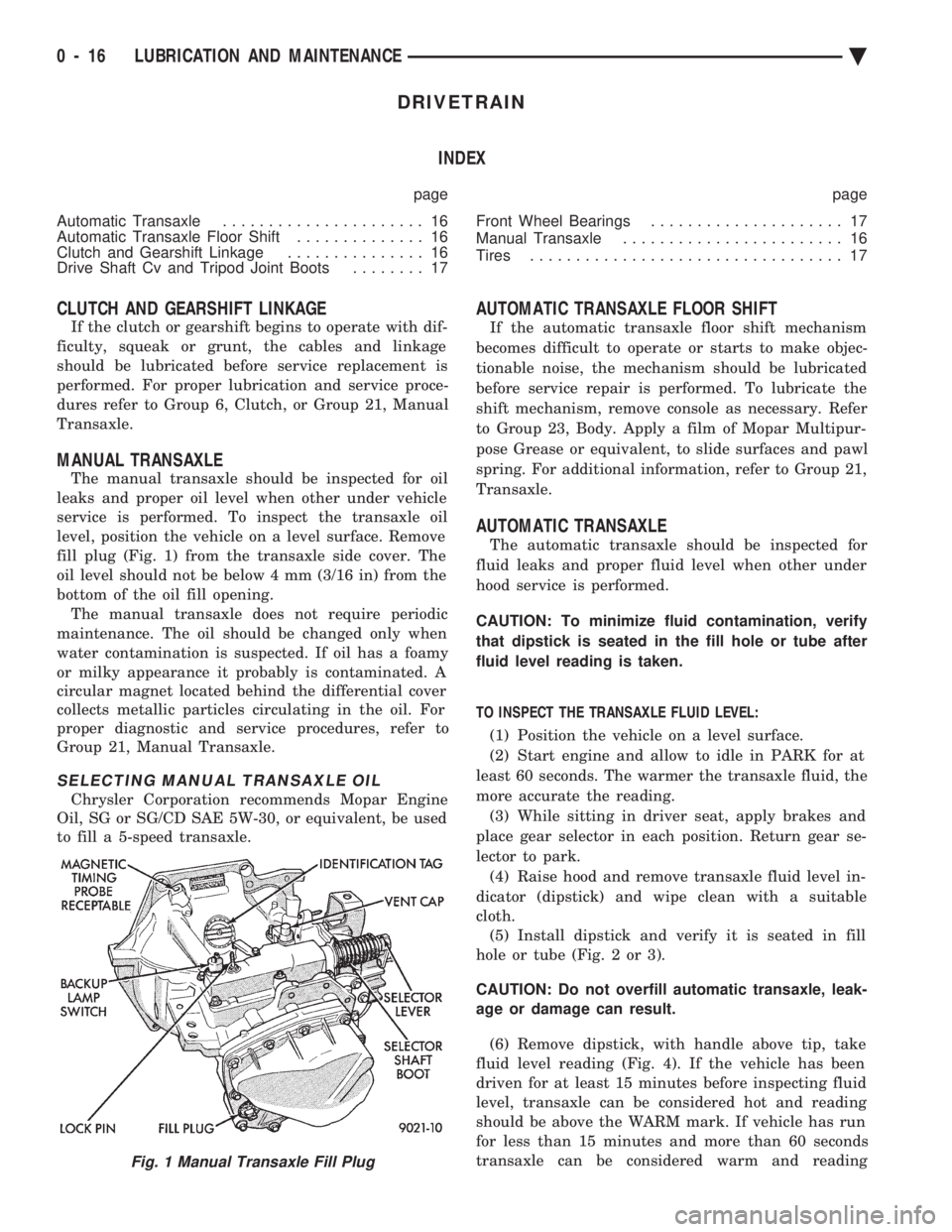
level, position the vehicle on a level surface. Remove
fill plug (Fig. 1) from the transaxle side cover. The
oil level should not be below 4 mm (3/16 in) from the
bottom of the oil fill opening. The manual transaxle does not require periodic
maintenance. The oil should be changed only when
water contamination is suspected. If oil has a foamy
or milky appearance it probably is contaminated. A
circular magnet located behind the differential cover
collects metallic particles circulating in the oil. For
proper diagnostic and service procedures, refer to
Group 21, Manual Transaxle.
SELECTING MANUAL TRANSAXLE OIL
Chrysler Corporation recommends Mopar Engine
Oil, SG or SG/CD SAE 5W-30, or equivalent, be used
to fill a 5-speed transaxle.
AUTOMATIC TRANSAXLE FLOOR SHIFT
If the automatic transaxle floor shift mechanism
becomes difficult to operate or starts to make objec-
tionable noise, the mechanism should be lubricated
before service repair is performed. To lubricate the
shift mechanism, remove console as necessary. Refer
to Group 23, Body. Apply a film of Mopar Multipur-
pose Grease or equivalent, to slide surfaces and pawl
spring. For additional information, refer to Group 21,
Transaxle.
AUTOMATIC TRANSAXLE
The automatic transaxle should be inspected for
fluid leaks and proper fluid level when other under
hood service is performed.
CAUTION: To minimize fluid contamination, verify
that dipstick is seated in the fill hole or tube after
fluid level reading is taken.
TO INSPECT THE TRANSAXLE FLUID LEVEL: (1) Position the vehicle on a level surface.
(2) Start engine and allow to idle in PARK for at
least 60 seconds. The warmer the transaxle fluid, the
more accurate the reading. (3) While sitting in driver seat, apply brakes and
place gear selector in each position. Return gear se-
lector to park. (4) Raise hood and remove transaxle fluid level in-
dicator (dipstick) and wipe clean with a suitable
cloth. (5) Install dipstick and verify it is seated in fill
hole or tube (Fig. 2 or 3).
CAUTION: Do not overfill automatic transaxle, leak-
age or damage can result.
(6) Remove dipstick, with handle above tip, take
fluid level reading (Fig. 4). If the vehicle has been
driven for at least 15 minutes before inspecting fluid
level, transaxle can be considered hot and reading
should be above the WARM mark. If vehicle has run
for less than 15 minutes and more than 60 seconds
transaxle can be considered warm and reading
Fig. 1 Manual Transaxle Fill Plug
0 - 16 LUBRICATION AND MAINTENANCE Ä
Page 55 of 2438

CHASSIS AND BODY INDEX
page page
Body Lubrication ......................... 22
Brakes ................................ 21
Headlamps ............................. 22
Lower Ball Joints ......................... 19 Power Steering
.......................... 19
Rear Wheel Bearings ..................... 20
Steering Linkage ......................... 19
STEERING LINKAGE
INSPECTION
The steering linkage and steering gear should be in-
spected for wear, leaks or damage when other under ve-
hicle service is performed. The rack and pinion steering
gear end boots should not have excess oil or grease res-
idue on the outside surfaces or surrounding areas
(Fig.1). If boot is leaking, it should be repaired. For
proper service procedures, see Group 19, Steering.
The tie rod end seal should fit securely between the
steering knuckle and tie rod end (Fig.2). The steering
linkage should be lubricated at the time and distance
intervals described in the Lubrication and Mainte-
nance Schedules. Refer to General Information sec-
tion of this group.
TIE ROD END LUBRICATION
Lubricate the steering linkage with Mopar, Multi-
mileage Lube or equivalent. Using a wiping cloth,
clean grease and dirt from around grease fitting and
joint seal. Using a grease gun, fill tie rod end until
lubricant leaks from around the tie rod end side of
the seal (Fig.2). When lube operation is complete,
wipe off excess grease.
LOWER BALL JOINTS
INSPECTION
The front suspension lower ball joints should be in-
spected for wear, leaks or damage when other under ve- hicle service is performed. The ball joint seal should fit
securely between the steering knuckle and lower control
arm (Fig. 3). The ball joints should be lubricated at the
time and distance intervals described in the Lubrication
and Maintenance Schedules. Refer to the General Infor-
mation section of this group.
BALL JOINT LUBRICATION
CAUTION: Do not over fill ball joint with grease,
damage to seal can result.
Lubricate the ball joints with Mopar, Multi-mile-
age Lube or equivalent. Using a wiping cloth, clean
grease and dirt from around grease fitting and joint
seal. Using a grease gun, fill ball joint until seal
starts to swell (Fig. 3). When lube operation is com-
plete, wipe off excess grease.
POWER STEERING
The power steering fluid level should be inspected
when other under hood service is performed. If the
fluid level is low and system is not leaking, use Mo-
par, Power Steering Fluid or equivalent. The power
steering system should be inspected for leaks when
other under vehicle service is performed. For proper
service procedures, refer to Group 19, Steering.Fig. 1 Inspect Steering Linkage
Fig. 2 Tie Rod End Lubrication
Ä LUBRICATION AND MAINTENANCE 0 - 19
Page 58 of 2438

BRAKE RESERVOIR LEVEL INSPECTION
WARNING: DO NOT ALLOW PETROLEUM OR WATER
BASE LIQUIDS TO CONTAMINATE BRAKE FLUID,
SEAL DAMAGE AND BRAKE FAILURE CAN RESULT.
RELIEVE PRESSURE IN ANTI-LOCK BRAKE SYS-
TEM BEFORE ADDING BRAKE FLUID TO RESER-
VOIR. IF NOT, BRAKE FLUID COULD DISCHARGED
FROM THE RESERVOIR POSSIBLY CAUSING PER-
SONAL INJURY.
The brake reservoir level should be inspected when
other under hood service is performed. It is normal
for the reservoir level to drop as disc brake pads
wear. When fluid must be added, use Mopar, Brake
Fluid or equivalent. Use only brake fluid conforming
to DOT 3, Federal, Department of Transportation
specification. To avoid brake fluid contamination, use
fluid from a properly sealed container. On vehicles with anti-lock brakes, depressurize the
system before inspecting fluid level. Turn OFF the
ignition and remove the key. Pump the brake pedal
at least 50 times to relieve the pressure in the sys-
tem.
On all vehicles, if fluid should become low after sev-
eral thousand kilometers (miles), fill the reservoir to
level marks on the side of the reservoir (Fig. 8 or 9).
HEADLAMPS
The headlamps should be inspected for intensity
and aim whenever a problem is suspected. When lug-
gage compartment is heavily loaded, the headlamp
aim should be adjusted to compensate for vehicle
height change. For proper service procedures, refer to
Group 8L, Lamps. DRIVER SUPPLEMENTAL AIRBAG SYSTEM
If the AIRBAG indicator lamp does not light at all,
stays lit or lights momentarily or continuously while
driving, a malfunction may have occurred. Prompt service is required. Refer to Group 8M, Restraint
Systems for proper diagnostic procedures.
BODY LUBRICATION
Body mechanisms and linkages should be inspected,
cleaned and lubricated as required to maintain ease of
operation and to prevent corrosion and wear. Before a component is lubricated, oil, grease and dirt
should be wiped off. If necessary, use solvent to clean
component to be lubricated. After lubrication is com-
plete, wipe off excess grease or oil. During winter season, external lock cylinders should
be lubricated with Mopar, Lock Lubricant or equiva-
lent to ensure proper operation when exposed to water
and ice. To assure proper hood latching component operation,
use engine oil to lubricate the lock, safety catch and
hood hinges when other under hood service is per-
formed. Mopar, Multi-purpose Grease or equivalent
should be applied sparingly to all pivot and slide
contact areas.
USE ENGINE OIL ON:
² Door hingesÐHinge pin and pivot points.
² Hood hingesÐPivot points.
² Luggage compartment lid hingesÐPivot points.
USE MOPAR LUBRIPLATE OR EQUIVALENT ON:
² Door check straps.
² Hood counterbalance springs.
² Luggage compartment lid latches.
² Luggage compartment lid prop rod pivots.
² Ash tray slides.
² Fuel Fill Door latch mechanism.
² Park brake mechanism.
² Front seat tracks.
Fig. 8 Anti-lock Brake Reservoir
Fig. 9 Master Cylinder Brake ReservoirÐExcept
Anti-lock
0 - 22 LUBRICATION AND MAINTENANCE Ä
Page 72 of 2438

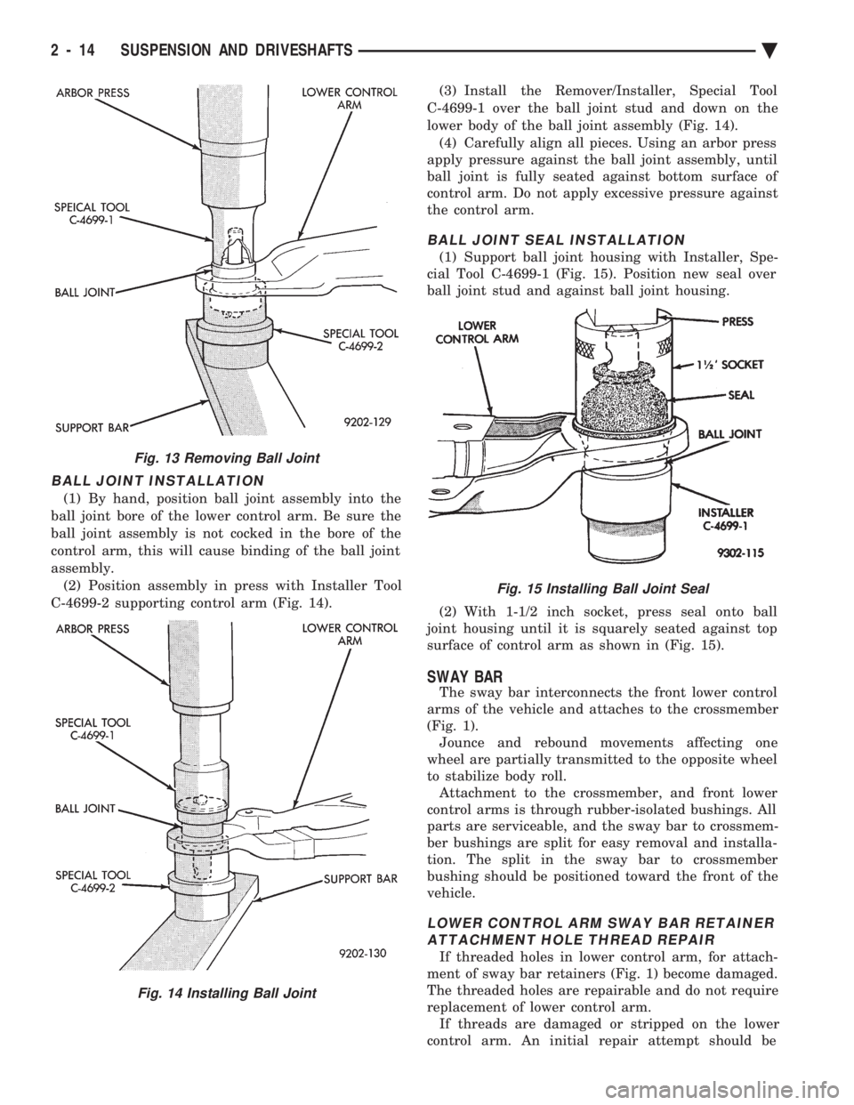
BALL JOINT INSTALLATION
(1) By hand, position ball joint assembly into the
ball joint bore of the lower control arm. Be sure the
ball joint assembly is not cocked in the bore of the
control arm, this will cause binding of the ball joint
assembly. (2) Position assembly in press with Installer Tool
C-4699-2 supporting control arm (Fig. 14). (3) Install the Remover/Installer, Special Tool
C-4699-1 over the ball joint stud and down on the
lower body of the ball joint assembly (Fig. 14). (4) Carefully align all pieces. Using an arbor press
apply pressure against the ball joint assembly, until
ball joint is fully seated against bottom surface of
control arm. Do not apply excessive pressure against
the control arm.
BALL JOINT SEAL INSTALLATION
(1) Support ball joint housing with Installer, Spe-
cial Tool C-4699-1 (Fig. 15). Position new seal over
ball joint stud and against ball joint housing.
(2) With 1-1/2 inch socket, press seal onto ball
joint housing until it is squarely seated against top
surface of control arm as shown in (Fig. 15).
SWAY BAR
The sway bar interconnects the front lower control
arms of the vehicle and attaches to the crossmember
(Fig. 1). Jounce and rebound movements affecting one
wheel are partially transmitted to the opposite wheel
to stabilize body roll. Attachment to the crossmember, and front lower
control arms is through rubber-isolated bushings. All
parts are serviceable, and the sway bar to crossmem-
ber bushings are split for easy removal and installa-
tion. The split in the sway bar to crossmember
bushing should be positioned toward the front of the
vehicle.
LOWER CONTROL ARM SWAY BAR RETAINER ATTACHMENT HOLE THREAD REPAIR
If threaded holes in lower control arm, for attach-
ment of sway bar retainers (Fig. 1) become damaged.
The threaded holes are repairable and do not require
replacement of lower control arm. If threads are damaged or stripped on the lower
control arm. An initial repair attempt should be
Fig. 13 Removing Ball Joint
Fig. 14 Installing Ball Joint
Fig. 15 Installing Ball Joint Seal
2 - 14 SUSPENSION AND DRIVESHAFTS Ä
Page 90 of 2438

INNER C/V JOINT
DISASSEMBLE
With driveshaft assembly removed from vehicle,
identify unit type (See Fig. 2 under Driveshafts Iden-
tification). (1) Remove the boot clamps and pull back the boot
to gain access to the tripod retention system, which
prevents accidental separation from the C/V joint
housing.
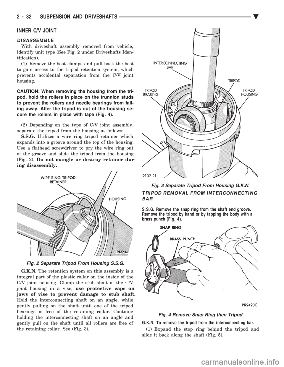
CAUTION: When removing the housing from the tri-
pod, hold the rollers in place on the trunnion studs
to prevent the rollers and needle bearings from fall-
ing away. After the tripod is out of the housing se-
cure the rollers in place with tape (Fig. 4).
(2) Depending on the type of C/V joint assembly,
separate the tripod from the housing as follows: S.S.G. Utilizes a wire ring tripod retainer which
expands into a groove around the top of the housing.
Use a flathead screwdriver to pry the wire ring out
of the groove and slide the tripod from the housing
(Fig. 2). Do not mangle or destroy retainer dur-
ing disassembly.
G.K.N. The retention system on this assembly is a
integral part of the plastic collar on the inside of the
C/V joint housing. Clamp the stub shaft of the C/V
joint housing in a vise, use protective caps on
jaws of vise to prevent damage to stub shaft.
Hold the interconnecting shaft on an angle, while
gently pulling on the shaft until one of the tripod
bearings is free of the retaining collar. Continue
holding the interconnecting shaft on an angle and
gently pull on the shaft until all rollers are free of
the retaining collar. See (Fig. 3).
TRIPOD REMOVAL FROM INTERCONNECTING BAR
S.S.G. Remove the snap ring from the shaft end groove.
Remove the tripod by hand or by tapping the body with a
brass punch (Fig. 4).
G.K.N. To remove the tripod from the interconnecting bar.
(1) Expand the stop ring behind the tripod and
slide it back along the shaft (Fig. 5).
Fig. 2 Separate Tripod From Housing S.S.G.
Fig. 3 Separate Tripod From Housing G.K.N.
Fig. 4 Remove Snap Ring then Tripod
2 - 32 SUSPENSION AND DRIVESHAFTS Ä
Page 91 of 2438

(2) Slide the tripod back along the shaft, either by
hand or by tapping the body with a brass drift. This
will expose the circlip on the end of the interconnect-
ing bar. (3) Remove the circlip from the end of intercon-
necting bar (Fig. 6).
(4) Remove the tripod from the interconnecting
bar. It is not necessary to remove the stop ring from
the interconnecting bar unless the bar is being re-
placed (Fig. 7). S.S.G. AND G.K.N. WITH SINGLE RING TRIPOD
RETENTION.
Remove the tripod assembly to interconnecting
shaft retaining snap ring from the interconnecting
shaft end groove (Fig. 8). Remove the tripod assem-
bly from the interconnecting shaft by hand or by tap-
ping the body of the tripod assembly with a brass
punch (Fig. 9).
G.K.N. WITH DOUBLE RING TRIPOD RETENTION. (1) Expand and remove the outer tripod assembly
to interconnecting shaft, retaining snap ring (Fig.
10). (2) Remove the tripod assembly from the intercon-
necting shaft. Tripod can be removed either by hand
or by tapping the tripod body with a brass drift (Fig.
4). Do not hit the outer tripod bearings in an attempt
to remove tripod assembly from interconnecting
shaft. (3) Remove inner tripod assembly to interconnect-
ing shaft, retaining snap ring from interconnecting
shaft (Fig. 11).
Fig. 5 Removing Stop Ring (G.K.N.)
Fig. 6 Removing Circlip
Fig. 7 Tripod Removed From The Interconnecting Bar
Fig. 8 Outer Tripod Retaining Snap Ring Removal
Ä SUSPENSION AND DRIVESHAFTS 2 - 33
Page 92 of 2438

INSPECT TRIPOD AND HOUSING
Remove as much grease as possible from assembly
and inspect joint housing ball raceway and tripod components for EXCESSIVE wear and replace if nec-
essary.
Inspect the spring, spring cup, and the spherical end
of the connecting shaft for EXCESSIVE wear or dam-
age and replace, if necessary.
ASSEMBLE C/V JOINT
TRIPOD ASSEMBLY INSTALLATION G.K.N.
(1) Slide rubber washer seal over stub shaft and
down into the groove provided (Fig. 12). The rubber
washer seal is used only on the right inner C/V
joint on the Equal Length Drive Shaft Systems.
(2) Fasten the (new) boot to the interconnecting
shaft. See Boots Install. (3) Slide the stop ring back into the stop ring groove
on the interconnecting bar (Fig. 5). (4) Install a new circlip in the circlip groove on the
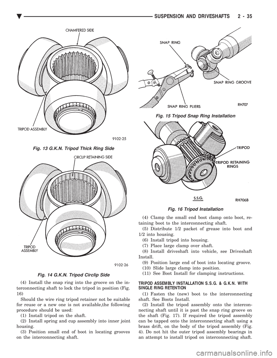
interconnecting bar (Fig. 6). (5) With the chamfered end (Fig. 13 & 14 ) of the
tripod facing the stop ring. Align the tripod splines and
push or tap on the body of the tripod assembly with a
SOFT drift, until tripod is seated on the shaft. Check
to make sure that the Tripod is Engaged by
attempting to pull the tripod off of the shaft by
hand.
TRIPOD ASSEMBLY INSTALLATION S.S.G. (1) Slide rubber washer seal over stub shaft and
down into the groove provided (Fig. 12). The rubber
washer seal is used only on the right inner C/V
joint on the Equal Length Drive Shaft Systems. (2) Fasten the (new) boot to the interconnecting
shaft. See Boots Install. (3) Install first wire ring tripod retainer over inter-
connecting shaft, slide tripod on the shaft, both ends
are the same (Fig. 15).
Fig. 9 Tripod Assembly Removal From Interconnecting Shaft
Fig. 10 Removing Outer Tripod Retaining Snap Ring (G.K.N.)
Fig. 11 Removing Inner Tripod Retaining Snap Ring(G.K.N.)
Fig. 12 Rubber Washer Seal Installation
2 - 34 SUSPENSION AND DRIVESHAFTS Ä
Page 93 of 2438

(4) Install the snap ring into the groove on the in-
terconnecting shaft to lock the tripod in position (Fig.
16) Should the wire ring tripod retainer not be suitable
for reuse or a new one is not available,the following
procedure should be used: (1) Install tripod on the shaft.
(2) Install spring and cup assembly into inner joint
housing. (3) Position small end of boot in locating grooves
on the interconnecting shaft. (4) Clamp the small end boot clamp onto boot, re-
taining boot to the interconnecting shaft. (5) Distribute 1/2 packet of grease into boot and
1/2 into housing. (6) Install tripod into housing.
(7) Place large clamp over shaft.
(8) Install driveshaft into vehicle, see Driveshaft
Install. (9) Position large end of boot into locating groove.
(10) Slide large clamp into position.
(11) See Boot Install for clamping instructions.
TRIPOD ASSEMBLY INSTALLATION S.S.G. & G.K.N. WITH
SINGLE RING RETENTION
(1) Fasten the (new) boot to the interconnecting
shaft. See Boots Install. (2) Install the tripod assembly onto the intercon-
necting shaft until it is past the snap ring groove on
the shaft (Fig. 17). If required the tripod assembly
can be tapped onto the interconnecting shaft using a
brass drift, on the body of the tripod assembly (Fig.
4). Do not hit the outer tripod assembly bearings in
an attempt to install tripod on interconnecting shaft.
Fig. 13 G.K.N. Tripod Thick Ring Side
Fig. 14 G.K.N. Tripod Circlip Side
Fig. 15 Tripod Snap Ring Installation
Fig. 16 Tripod Installation
Ä SUSPENSION AND DRIVESHAFTS 2 - 35