1993 CHEVROLET PLYMOUTH ACCLAIM AA body
[x] Cancel search: AA bodyPage 195 of 2438
REAR DISC BRAKES INDEX
page page
Assembling Rear Disc Brake Caliper .......... 49
Brake Shoe Removal ..................... 46
Cleaning and Inspection ................... 49
Disassembling Rear Caliper Assembly ......... 48 General Information
....................... 45
Lining Wear ............................. 45
Service Precautions ....................... 46
GENERAL INFORMATION
The rear disc brakes are similar to front disc
brakes, however, there are several distinctive fea-
tures that require different service procedures. This
single piston, floating caliper rear disc brake assem-
bly includes a hub assembly, adapter, braking disc
(rotor), caliper, shoes and linings. The parking brake
system on all vehicles equipped with rear disc
brakes. Consists of a small duo-servo drum brake
mounted to the caliper adapter. The drum brake
shoes expand out against a braking surface (hat sec-
tion) on the inside area of the braking disk (rotor). The AC and AY body vehicles are equipped with a
caliper assembly that has a 36 mm (1.42 inch) piston,
and utilizes a 14 inch solid braking disc (rotor). The AA body vehicle are equipped with a caliper
assembly that uses a 34 mm (1.34 inch) piston. The
AA body uses the same 14 inch solid braking disc
(rotor) as on the AC and AY applications. Also avail-
able on the AA body is a caliper assembly with a 36
mm (1.42 inch) piston, with a 15 inch vented braking
disc (rotor). The AG AJ and AP body vehicles are also equipped
with different size caliper pistons depending on the size and type of braking disk used on the vehicle.
The 14 9solid braking disk (rotor) applications use a
34 mm (1.34 inch) piston, and the 15 9vented braking
disk (rotor) applications use a 36 mm (1.42 inch) pis-
ton. The caliper assembly on all applications float on
rubber bushings using internal metal sleeves which
are attached to the adapter using threaded guide pin
bolts. The adapter is mounted to the rear axle of the ve-
hicle and is used to mount the brake shoes and actu-
ating cables for the parking brake system. The
adapter also mounts the rear caliper assembly to the
vehicle. The adapter has two machined abutments
which are used to position and align the caliper and
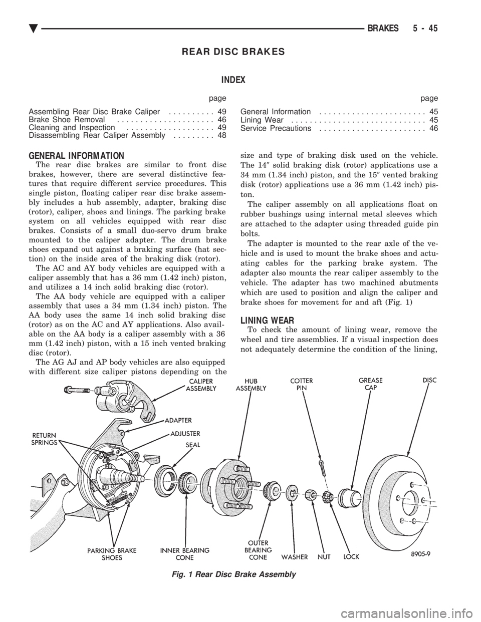
brake shoes for movement for and aft (Fig. 1)
LINING WEAR
To check the amount of lining wear, remove the
wheel and tire assemblies. If a visual inspection does
not adequately determine the condition of the lining,
Fig. 1 Rear Disc Brake Assembly
Ä BRAKES 5 - 45
Page 199 of 2438

tool for this operation, because of the possibility
of scratching piston bore or burring edges of seal
groove. The double pin caliper uses a sealed for life bushing
and sleeve assembly. If required this assembly can be
serviced using the following procedure. (1) Using your fingers push on one end the inner
sleeve until it pops out of the bushing. Then grasp the
inner sleeve with your fingers and pull the inner sleeve
out from the inside of the bushing (Fig. 3). (2) Using your fingers collapse one side of the bush-
ing. Then pull on the opposite side to remove the
bushing from the caliper assembly (Fig. 4).
CLEANING AND INSPECTION
Clean all parts using alcohol or a suitable solvent
and wipe dry. Clean out all drilled passages and bores
on the caliper assembly body. (Whenever a caliper
has been disassembled, a new boot and seal must
be installed at assembly). Inspect the caliper assembly piston bore for scoring
or pitting. Bores that show light scratches or corrosion,
can usually have the scratches or corrosion removed
using crocus cloth. Bores that have deep scratches or scoring should be
honed. Use Caliper Hone, Special Tool C-4095, or
equivalent providing the diameter of the bore is not
increased more than 0.0254 mm (0.001 inch) (Fig. 5). If the bore does not clean up within this specification,
a new caliper housing should be installed. Install a new
piston if the old one is pitted or scored. When using Caliper Honing Tool, Special Tool
C-4095, coat the stones and bore with brake fluid.
After honing the bore, carefully clean the seal
and boot grooves with a stiff non-metallic rotary
brush. Use extreme care in cleaning the caliper after
honing. Remove all dirt and grit by flushing the
caliper with brake fluid; wipe dry with a clean,
lint free cloth and then clean a second time.
ASSEMBLING REAR DISC BRAKE CALIPER
Clamp caliper in vise (with protective caps on vise
jaws).
Fig. 2 Removing Piston Seal
Fig. 3 Removing Inner Sleeve From Bushing
Fig. 4 Removing Bushings From Caliper
Ä BRAKES 5 - 49
Page 207 of 2438
PARKING BRAKES INDEX
page page
Adjust Parking Brake (AG & AJ Body) ........ 61
General Information ....................... 57
Installing Parking Brake Front Cable (AA, AC, AP AY Body) ............................. 62
Installing Parking Brake Shoes .............. 64
Parking Brake Hand Lever Assembly Removal and Installation ............................ 63
Rear Parking Brake Cable Installation ......... 62 Rear Parking Brake Cable Removal (AA, AC, AP,
AY Body) ............................. 61
Removal and Installation Parking Brake Shoes . . 63
Removing Parking Brake Front Cable (AA, AC, AP, AY Body) ............................. 62
Self Adjusting Procedures (AG & AJ Body) ..... 61
Service Procedures ....................... 57
GENERAL INFORMATION
The parking brake mechanism on vehicles with
rear disc brake applications. Consists of a small duo-
servo brake which is mounted to the adapter. The
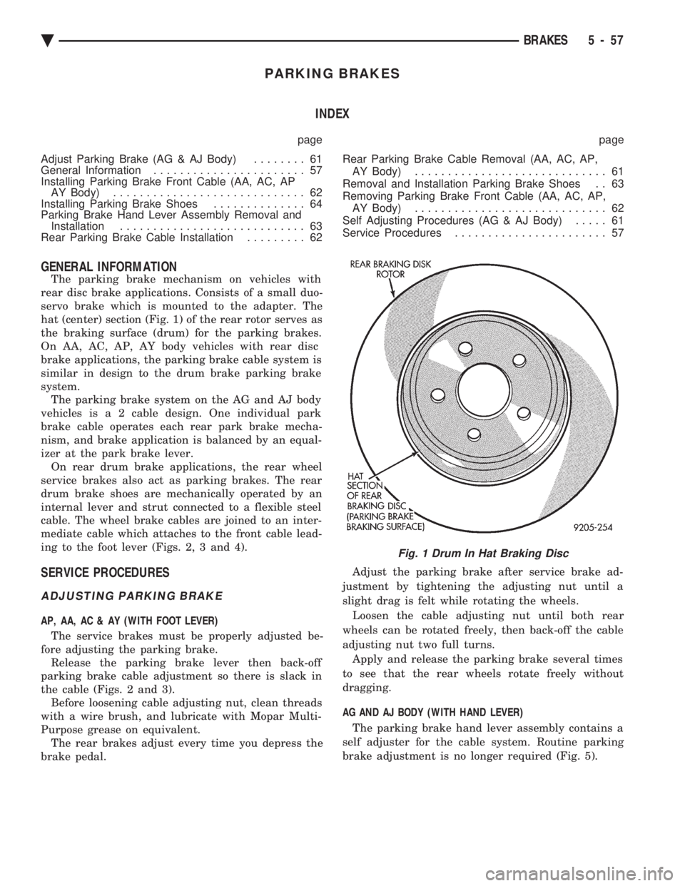
hat (center) section (Fig. 1) of the rear rotor serves as
the braking surface (drum) for the parking brakes.
On AA, AC, AP, AY body vehicles with rear disc
brake applications, the parking brake cable system is
similar in design to the drum brake parking brake
system. The parking brake system on the AG and AJ body
vehicles i s a 2 cable design. One individual park
brake cable operates each rear park brake mecha-
nism, and brake application is balanced by an equal-
izer at the park brake lever. On rear drum brake applications, the rear wheel
service brakes also act as parking brakes. The rear
drum brake shoes are mechanically operated by an
internal lever and strut connected to a flexible steel
cable. The wheel brake cables are joined to an inter-
mediate cable which attaches to the front cable lead-
ing to the foot lever (Figs. 2, 3 and 4).
SERVICE PROCEDURES
ADJUSTING PARKING BRAKE
AP, AA, AC & AY (WITH FOOT LEVER)
The service brakes must be properly adjusted be-
fore adjusting the parking brake. Release the parking brake lever then back-off
parking brake cable adjustment so there is slack in
the cable (Figs. 2 and 3). Before loosening cable adjusting nut, clean threads
with a wire brush, and lubricate with Mopar Multi-
Purpose grease on equivalent. The rear brakes adjust every time you depress the
brake pedal. Adjust the parking brake after service brake ad-
justment by tightening the adjusting nut until a
slight drag is felt while rotating the wheels. Loosen the cable adjusting nut until both rear
wheels can be rotated freely, then back-off the cable
adjusting nut two full turns. Apply and release the parking brake several times
to see that the rear wheels rotate freely without
dragging.
AG AND AJ BODY (WITH HAND LEVER) The parking brake hand lever assembly contains a
self adjuster for the cable system. Routine parking
brake adjustment is no longer required (Fig. 5).
Fig. 1 Drum In Hat Braking Disc
Ä BRAKES 5 - 57
Page 208 of 2438
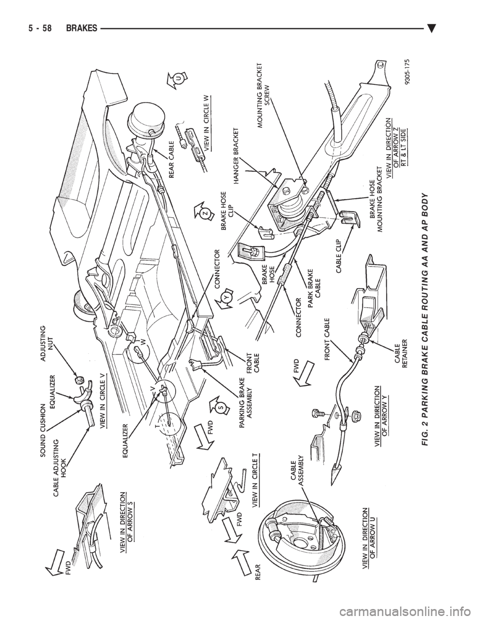
FIG. 2 PARKING BRAKE CABLE ROUTING AA AND AP BODY
5 - 58 BRAKES Ä
Page 209 of 2438
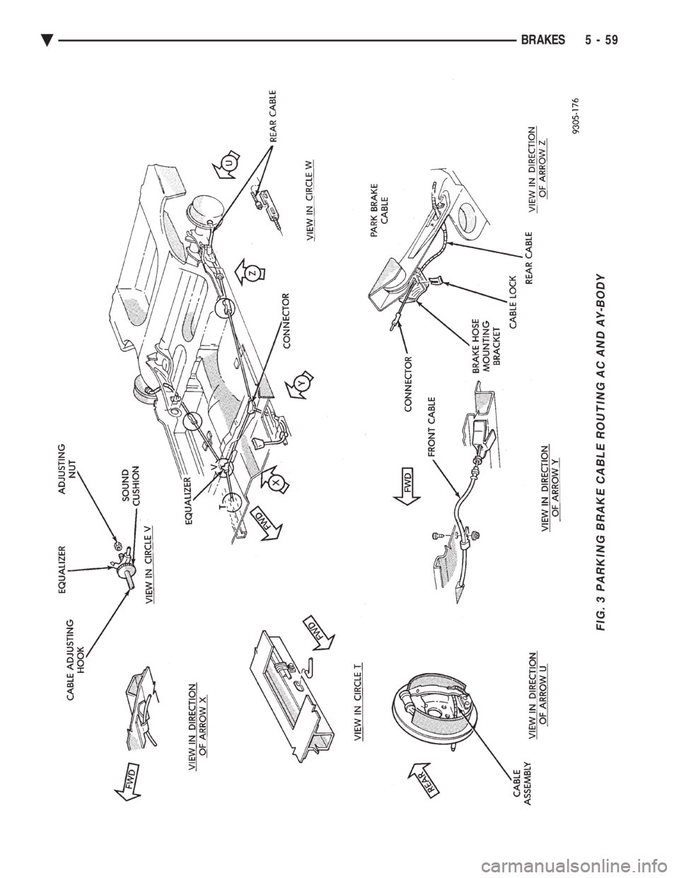
FIG. 3 PARKING BRAKE CABLE ROUTING AC AND AY-BODY
Ä BRAKES 5 - 59
Page 210 of 2438
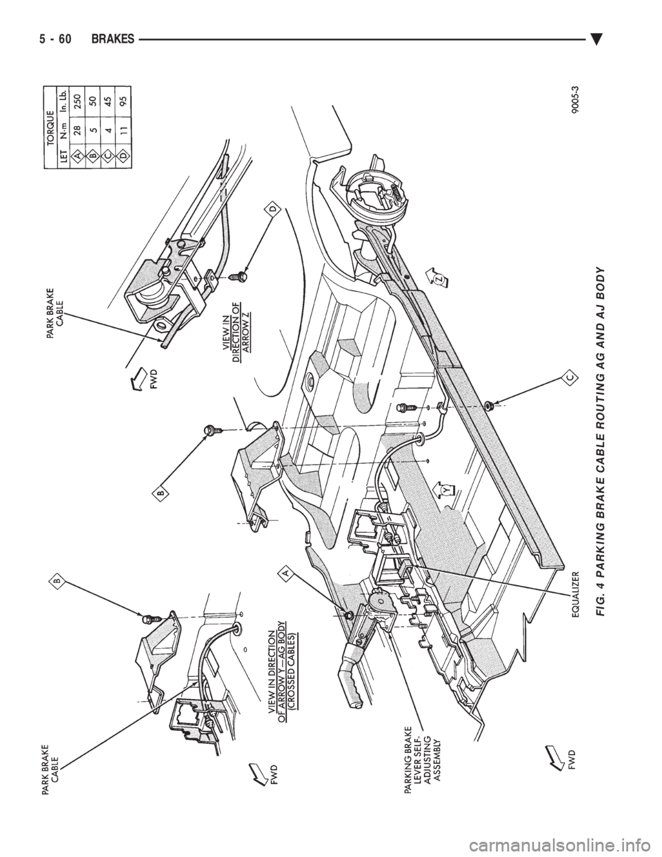
FIG. 4 PARKING BRAKE CABLE ROUTING AG AND AJ BODY
5 - 60 BRAKES Ä
Page 211 of 2438

WARNING: THE SELF ADJUSTING FEATURE OF THIS
PARKING BRAKE LEVER ASSEMBLY CONTAINS A
CLOCK SPRING LOADED TO APPROXIMATELY 30
POUNDS. CARE MUST BE TAKEN TO PREVENT EX-
CESSIVE JARRING OF THE ASSEMBLY. DO NOT
RELEASE THE SELF ADJUSTER LOCKOUT DEVICE
BEFORE INSTALLING CABLES INTO THE EQUAL-
IZER. KEEP HANDS OUT OF SELF ADJUSTER SEC-
TOR AND PAWL AREA. FAILURE TO OBSERVE CAU-
TION IN HANDLING THIS MECHANISM COULD LEAD
TO SERIOUS INJURY.
When repairs to the hand lever assembly or cable
system are required the self adjuster must be reloaded
and locked out.
SELF ADJUSTING PROCEDURES (AG & AJ BODY)
TO RELOAD SELF ADJUSTER
(1) Remove ash receiver or courtesy light from rear
of center console to gain access to self adjuster. Also,
remove carpet from sides of console. (2) Pull on equalizer/output cable to wind up sprin-
g(requires greater than 30 pounds effort). Continue
until self adjuster lockout pawl is positioned about
midway on the self adjuster sector (Fig. 6). Rotate
lockout pawl into self adjuster sector by turning allen
screw clockwise. Rotating lockout device requires
very little effort. Do not force or failure of lock-
out device will occur. (3) When repairs are complete, adjust rear brakes
before adjusting parking brake. On drum-in-hat type of
rear disc brake adjust shoe diameter to 171.5 mm (6.75
inch).
ADJUST PARKING BRAKE (AG & AJ BODY)
Be sure that the cables are properly assembled to the
equalizer bracket prior to cable adjustment. (1) Insert a 7/32 inch allen wrench into hex socket
and turn counter-clockwise through approximately 15É
of rotation (Fig. 4). In turning lockout device, self
adjuster release is a loud snapping noise followed by
reaching a more felt than heard detent. Very light
effort is required to seat lockout arm into detent.
Follow through to the detent is important in prevent-
ing the lockout rod from rattling. Note: The parking brake handle can be in any
position when releasing self adjuster. (2) Cycle lever to position cables. Rear wheels should
rotate freely without dragging.
REAR PARKING BRAKE CABLE REMOVAL (AA, AC,
AP, AY BODY)
The rear brake cables are attached to rear connec-
tors. Should it become necessary to remove either parking
brake cable for installation of a new cable, proceed as
follows: With vehicle jacked up on a suitable hoist, remove
wheel and tire assembly (Fig. 6). Back off cable adjusting nut to provide slack and
disconnect rear brake cable from connector.
DRUM BRAKES
(1) Disconnect park brake cable from park brake
lever in rear wheel brakes. (2) Using an aircraft type hose clamp compress re-
tainers on end of cable housing and start cable out of
retaining hole in the support plate. Remove clamp
when retainers are free of the mounting hole in the
support plate, (Fig. 6).
(3) Remove clip from brake cable at support
bracket and pull cable away from trailing arm as-
sembly (Figs. 3 and 4).
DISC BRAKES
(1) Remove disc brake caliper from adapter, and
brake disc (rotor) from rear hub.
Fig. 5 Self Adjusting Parking Brake Lever Assembly
Fig. 6 Removing Brake Cable from Support Plate
Ä BRAKES 5 - 61
Page 212 of 2438
(2) Disconnect parking brake cable from brake
shoe lever. (3) Using an aircraft type hose clamp compress re-
tainers on end of cable housing and start cable out of
retaining hole in the adapter. Remove clamp when
retainers are free of mounting hole in the adapter
(Fig. 6). (4) Remove clip from parking brake cable at
hanger bracket and pull cable away from trailing
arm.
REAR PARKING BRAKE CABLE INSTALLATION
DRUM BRAKES (AA, AC, AP, AY BODY)
(1) Route parking brake cable assembly through
trailing arm and hanger bracket. (2) Install parking brake cable retaining clip.
(3) Install parking brake cable into rear brake sup-
port plate. Be sure all retainers are expanded around
mounting hole in brake support plate, and then con-
nect parking brake cable end to brake shoe lever. (4) Insert forward end of parking brake cable into
connector. (5) Install brake drum, and wheel and tire assem-
bly.
DRUM BRAKES (AG & AJ BODY)
(1) Route each parking brake cable assembly
through trailing arm and mounting bracket. (2) Install parking brake cable retaining clip.
(3) Install parking brake cable into rear brake sup-
port plate. Be sure the retainers are expanded
around mounting hole in the brake support plate and
connect parking brake cable end to brake shoe lever. (4) Insert forward end of parking brake cable into
floor pan of vehicle. Then connector park brake cable
to equalizer at park brake hand lever. (5) Install brake drum, and wheel and tire assem-
bly.
DISC BRAKES (AA, AC, AP, AY BODY)
(1) Route parking brake cable assembly through
trailing arm and parking brake cable hanger
bracket. (2) Install parking brake cable to hanger bracket
retaining clip. (3) Install parking brake cable into rear brake
adapter. Be sure all cable retainers on parking brake
cable are expanded around mounting hole in adapter
and connect cable end to brake shoe lever. (4) Insert forward end of cable into connector.
(5) Adjust parking brake shoe diameter to 171 mm
(6.75 inch). (6) Install rear braking disc, caliper assembly and
wheel and tire assembly.
DISC BRAKES (AG & AJ BODY)
(1) Route each individual parking brake cable as-
sembly through trailing arm and parking brake ca-
ble mounting bracket. (2) Install parking brake cable to mounting
bracket retaining clip. (3) Install parking brake cable into rear disc brake
adapter. Be sure all cable retainers on parking brake
cable are expanded around mounting hole in adapter,
and then connect cable end to brake shoe lever. (4) Insert forward end of parking brake cable into
floor pan of vehicle. Then connector park brake cable
to equalizer at park brake hand lever. (5) Adjust parking brake shoe diameter to 171 mm
(6.75 inch). (6) Install rear braking disc, caliper assembly and
wheel and tire assembly.
REMOVING PARKING BRAKE FRONT CABLE (AA,
AC, AP, AY BODY)
(1) Loosen parking brake cable adjusting nut un-
der car. Disengage front cable from intermediate ca-
ble connector (Fig. 2). (2) Remove park brake cable retaining clip from
floor pan of vehicle. (3) Lift floor mat for access to floor pan.
(4) Remove floor pan seal.
(5) Pull parking brake cable strand end forward
and disconnect from foot lever clevis. Separate park-
ing brake cable from parking brake foot lever and
bracket on body rail. (6) Pull parking brake cable assembly through
hole in floor pan and up into vehicle.
INSTALLING PARKING BRAKE FRONT CABLE (AA,
AC, AP AY Body)
(1) Insert parking brake cable housing retainers
into hole in rail bracket and parking brake foot lever
assembly (Fig. 2). (2) Feed parking brake cable end through holes in
floor pan and rail bracket, from the interior of the
vehicle. (3) Install floor pan seal.
(4) Engage parking brake cable strand end in foot
lever clevis. Seat cable ends in parking brake assem-
bly and parking brake cable rail bracket. (5) Replace floor mat.
(6) Attach park brake cable retaining clip to floor
pan of vehicle. (7) Engage rear parking brake cable end to inter-
mediate cable connector. (8) Adjust service and parking brakes.
5 - 62 BRAKES Ä