1993 CHEVROLET PLYMOUTH ACCLAIM Index
[x] Cancel search: IndexPage 2244 of 2438
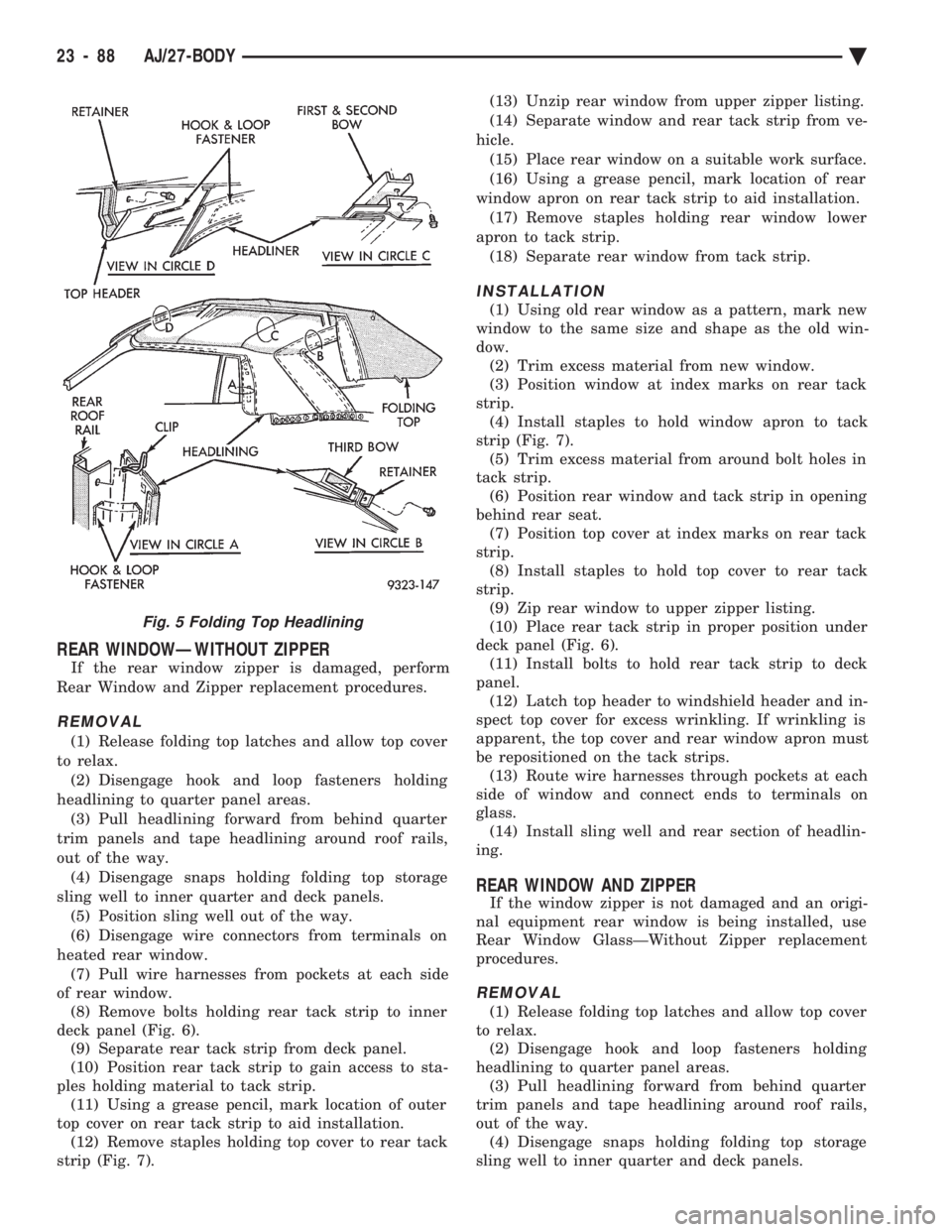
REAR WINDOWÐWITHOUT ZIPPER
If the rear window zipper is damaged, perform
Rear Window and Zipper replacement procedures.
REMOVAL
(1) Release folding top latches and allow top cover
to relax. (2) Disengage hook and loop fasteners holding
headlining to quarter panel areas. (3) Pull headlining forward from behind quarter
trim panels and tape headlining around roof rails,
out of the way. (4) Disengage snaps holding folding top storage
sling well to inner quarter and deck panels. (5) Position sling well out of the way.
(6) Disengage wire connectors from terminals on
heated rear window. (7) Pull wire harnesses from pockets at each side
of rear window. (8) Remove bolts holding rear tack strip to inner
deck panel (Fig. 6). (9) Separate rear tack strip from deck panel.
(10) Position rear tack strip to gain access to sta-
ples holding material to tack strip. (11) Using a grease pencil, mark location of outer
top cover on rear tack strip to aid installation. (12) Remove staples holding top cover to rear tack
strip (Fig. 7). (13) Unzip rear window from upper zipper listing.
(14) Separate window and rear tack strip from ve-
hicle. (15) Place rear window on a suitable work surface.
(16) Using a grease pencil, mark location of rear
window apron on rear tack strip to aid installation. (17) Remove staples holding rear window lower
apron to tack strip. (18) Separate rear window from tack strip.
INSTALLATION
(1) Using old rear window as a pattern, mark new
window to the same size and shape as the old win-
dow. (2) Trim excess material from new window.
(3) Position window at index marks on rear tack
strip. (4) Install staples to hold window apron to tack
strip (Fig. 7). (5) Trim excess material from around bolt holes in
tack strip. (6) Position rear window and tack strip in opening
behind rear seat. (7) Position top cover at index marks on rear tack
strip. (8) Install staples to hold top cover to rear tack
strip. (9) Zip rear window to upper zipper listing.
(10) Place rear tack strip in proper position under
deck panel (Fig. 6). (11) Install bolts to hold rear tack strip to deck
panel. (12) Latch top header to windshield header and in-
spect top cover for excess wrinkling. If wrinkling is
apparent, the top cover and rear window apron must
be repositioned on the tack strips. (13) Route wire harnesses through pockets at each
side of window and connect ends to terminals on
glass. (14) Install sling well and rear section of headlin-
ing.
REAR WINDOW AND ZIPPER
If the window zipper is not damaged and an origi-
nal equipment rear window is being installed, use
Rear Window GlassÐWithout Zipper replacement
procedures.
REMOVAL
(1) Release folding top latches and allow top cover
to relax. (2) Disengage hook and loop fasteners holding
headlining to quarter panel areas. (3) Pull headlining forward from behind quarter
trim panels and tape headlining around roof rails,
out of the way. (4) Disengage snaps holding folding top storage
sling well to inner quarter and deck panels.
Fig. 5 Folding Top Headlining
23 - 88 AJ/27-BODY Ä
Page 2245 of 2438
(5) Position sling well out of the way.
(6) Disengage wire connectors from terminals on
heated rear window. (7) Pull wire harnesses from pockets at each side
of rear window. (8) Remove bolts holding rear tack strip to inner
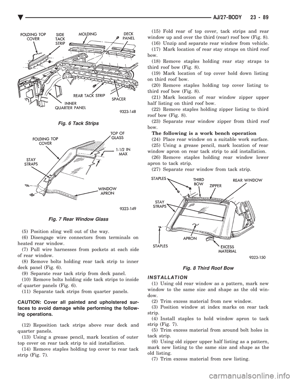
deck panel (Fig. 6). (9) Separate rear tack strip from deck panel.
(10) Remove bolts holding side tack strips to inside
of quarter panels (Fig. 6). (11) Separate tack strips from quarter panels.
CAUTION: Cover all painted and upholstered sur-
faces to avoid damage while performing the follow-
ing operations.
(12) Reposition tack strips above rear deck and
quarter panels. (13) Using a grease pencil, mark location of outer
top cover on rear tack strip to aid installation. (14) Remove staples holding top cover to rear tack
strip (Fig. 7). (15) Fold rear of top cover, tack strips and rear
window up and over the third (rear) roof bow (Fig. 8). (16) Unzip and separate rear window from vehicle.
(17) Mark location of rear stay straps on third roof
bow. (18) Remove staples holding rear stay straps to
third roof bow (Fig. 8). (19) Mark location of top cover hold down listing
on third roof bow. (20) Remove staples holding top cover listing to
third roof bow (Fig. 8). (21) Mark location of rear window zipper upper
half listing on third roof bow. (22) Remove staples holding zipper listing to third
roof bow (Fig. 8). (23) Separate rear window zipper from third roof
bow. The following is a work bench operation
(24) Place rear window on a suitable work surface.
(25) Using a grease pencil, mark location of rear
window apron on rear tack strip to aid installation. (26) Remove staples holding rear window lower
apron to tack strip. (27) Separate rear window from tack strip.
INSTALLATION
(1) Using old rear window as a pattern, mark new
window to the same size and shape as the old win-
dow. (2) Trim excess material from new window.
(3) Position window at index marks on rear tack
strip. (4) Install staples to hold window apron to tack
strip (Fig. 7). (5) Trim excess material from around bolt holes in
tack strip. (6) Using old zipper upper half listing as a pattern,
mark new listing to the same size and shape as the
old listing. (7) Trim excess material from new listing.
Fig. 6 Tack Strips
Fig. 7 Rear Window Glass
Fig. 8 Third Roof Bow
Ä AJ/27-BODY 23 - 89
Page 2246 of 2438
(8) Position zipper upper half listing at index
marks on the third roof bow. Verify that start end of
zipper upper half is at the same end as the rear win-
dow half. (9) Install staples to hold zipper listing to third
roof bow (Fig. 8). (10) Position top cover hold down listing at index
marks on third roof bow. (11) Install staples to hold top cover listing to third
roof bow (Fig. 8). (12) Position stay straps at index marks on the
third roof bow. (13) Install staples to hold stay straps to third roof
bow. (14) Zip rear window into position.
(15) Fold rear of top cover, tack strips and rear
window up and over the third roof bow to the rear of
the top opening (Fig. 8). (16) Position top cover at index marks at each end
of rear tack strip. (17) Install staples to hold top cover to rear tack
strip (Fig. 6). (18) Position side and rear tack strips behind quar-
ter and deck panels. (19) Install bolts to hold side tack strips to inside
of quarter panels (Fig. 6). (20) Install bolts to hold rear tack strip to deck
panel. (21) Latch top header to windshield header and in-
spect top cover for excess wrinkling. If wrinkling is
apparent, the top cover and rear window apron must
be repositioned on the tack strips. (22) Route wire harnesses through pockets at each
side of window and connect ends to terminals on
glass. (23) Install sling well and rear section of headlin-
ing.
FOLDING TOP COVER
REMOVAL
(1) Release folding top latches and allow top cover
to relax. (2) Remove headlining.
(3) Disengage snaps holding top storage sling well
to rear deck and quarter panels. (4) Position sling well out of the way.
(5) Remove bolts holding rear tack strip to inner
deck panel. (6) Separate rear tack strip from deck panel.
(7) Remove bolts holding side tack strips to inside
of quarter panels. (8) Separate tack strips from quarter panels.
CAUTION: Cover all painted and upholstered sur-
faces to avoid damage while performing the follow-
ing operations. (9) Reposition tack strips above rear deck and
quarter panels. (10) Using a grease pencil, mark location of outer
top cover on rear tack strip to aid installation. (11) Remove staples holding top cover to rear tack
strip. (12) Fold rear of top cover, tack strips and rear
window up and over the third (rear) roof bow. (13) Unzip and separate rear window from vehicle.
(14) Mark location of top cover hold down listing
on third roof bow. (15) Remove staples holding top cover listing to
third roof bow. (16) Remove screws holding roof rail tension cable
springs to roof rear roof rail behind quarter glass
opening. (17) Pull quarter glass weatherstrips from roof rail
channels. (18) Remove screws holding roof rail channels to
roof rails. (19) Separate roof rail channels from vehicle.
(20) Separate top cover listing from adhesive on
roof rail. (21) Lower folding top to the mid point.
(22) Pull top header weatherstrip from retaining
channel. Separate first 50 mm (2 in.) of weather strip
from roof rail channels. (23) Remove screws holding weatherstrip channel
to top header. (24) Separate channel from top header.
(25) Remove staples holding top header feature
strip to top header. (26) Separate feature strip from header.
(27) Mark location or top cover on top header.
(28) Remove staples holding top cover to header.
(29) Close folding top, do not latch.
(30) Remove rubber plugs holding roof rail tension
cable ends into key-hole slots in roof rails (31) Disengage roof rail tension cables from roof
rails. (32) Pull tension cables from rear of pockets on
back of top cover. (33) Remove screws holding top cover retainer rod
to second roof bow. (34) Separate retainer rod from second roof bow.
(35) Remove screws holding top cover retainer rod
to first roof bow. (36) Separate retainer rod from first roof bow.
(37) Separate top cover from vehicle.
(38) Pull retainer rod from listing pockets on back
of top cover.
INSTALLATION
The new top cover must be trimmed to the same
size and shape as the old top cover to minimize wrin-
kling after installation. Use the rear sections of the
old top as a pattern.
23 - 90 AJ/27-BODY Ä
Page 2247 of 2438
(1) On old top cover mark a line from the top of
the quarter glass opening to the center of rear glass
opening on each side of the top. (2) Using a suitable cutting tool, cut the rear quar-
ter sections off of old top. (3) Mark locations of old top cover on side tack
strips. (4) Remove staples holding old top cover to side
tack strips. (5) Using quarter sections cut from old top cover as
a pattern, mark lower tack strip edge of new top to
same size and shape as old top. (6) Trim excess material from new top cover.
(7) Position side tack strips under edge of new top
and align index marks. (8) Install staples 100 mm (4 in.) apart to hold top
cover to side tack strips. (9) Install retainer rod in listing pockets on back of
top cover. (10) Position top cover over top bows on vehicle
and center top cover side to side. (11) Mate retainer rod to first roof bow.
(12) Install screws to hold top cover retainer rod to
first roof bow. (13) Mate retainer rod to second roof bow.
(14) Install screws to hold top cover retainer rod to
second roof bow. (15) Route roof rail tension cables through rear of
pockets on back of top cover. (16) Connect roof rail tension cables to key-hole
slots in roof rails. (17) Install rubber plugs to hold roof rail tension
cable ends into key-hold slots in roof rails. (18) Apply suitable contact adhesive to roof rail
rear of quarter glass opening and back of top cover
hold down listing. (19) Stick top cover listing to roof rail.
(20) Place roof rail weatherstrip channel in proper
position. (21) Install screws to hold channel to roof rail.
(22) Position top cover listing at index marks on
third roof bow. (23) Install staples 10 mm (0.3 in.) apart to hold
top cover listing to third roof bow. (24) Zip rear window into position.
(25) Fold rear of top cover, tack strips and rear
window down and over the third roof bow. (26) Position top cover at index marks on rear tack
strip. (27) Install staples 100 mm (4 in.) apart to hold
top cover to rear tack strip.
CAUTION: Cover all painted and upholstered sur-
faces to avoid damage while performing the follow-
ing operations.
(28) Reposition tack strips under rear deck and
quarter panels. (29) Place side tack strips in position behind quar-
ter panels. (30) Install enough bolts to temporarily hold side
tack strips to inside of quarter panels. (31) Place rear tack strip in position behind deck
panel. (32) Install enough bolts to temporarily hold rear
tack strip to inner deck panel. (33) Close and latch folding top.
(34) Pull top cover forward over top of windshield
and hold cover material taut. (35) Mark location of froward lower edge of top
header on top cover material. (36) Release top latches and lower top to mid-
point. (37) Align marks on top material to front lower
edge of top header. (38) Verify that top cover will be wrinkle free and
aligned side to side. (39) Install staples 10 mm (0.3 in.) apart to hold
top cover to header. (40) Place top header feature strip in position un-
der top header. (41) Install staples 10 mm (0.3 in.) apart to hold
feature strip to top header. (42) Place weatherstrip channel in position under
top header. (43) Install screws to hold channel to top header.
(44) Insert top header weatherstrip into header
and roof rail channels. (45) Install screws to hold roof rail tension cable
springs to roof rear roof rail behind quarter glass
opening. (46) Close and latch top windshield header.
(47) Inspect top cover for excess wrinkling. If ex-
cess wrinkles are apparent, the top cover must be re-
positioned on the tack strips. (48) If top cover is smooth, release top header
latches to allow top cover to relax. (49) Remove bolts holding tack strips to deck and
quarter panels. (50) Install staples 10 mm (0.3 in.) apart to hold
top cover to rear and side tack strips. (51) Place side and rear tack strips in position.
(52) Install bolts to hold tack strips to deck and
quarter panels. (53) Insert quarter glass weatherstrips into roof
rail channels. (54) Place sling well into position.
(55) Engage snaps to hold sling well to rear deck
and quarter panels. Verify that drain tube is con-
nected to bottom of sling well. (56) Install headlining.
(57) Close top and latch header to windshield
header.
Ä AJ/27-BODY 23 - 91
Page 2253 of 2438
AP-VEHICLE BODY COMPONENT SERVICE INDEX
page page
A-Pillar and Roof Rail Mouldings ............ 109
B-Pillar Trim PanelÐAP-44 Body ............ 109
Body Side Moulding and Applique ........... 108
Cowl Panel Trim and Scuff Plates ........... 109
Door Opening Weatherstrips ............... 107
Floor Carpet ........................... 113
Front Center Console .................... 113
Front Door and Hinge .................... 100
Front Door Belt Moulding and Weatherstrip .... 102
Front Door Glass ........................ 101
Front Door Glass Channel and Run Weatherstrip .......................... 103
Front Door Glass Run Lower Channels ....... 103
Front Door Latch ........................ 101
Front Door Side View Mirror ............... 101
Front Door Trim PanelÐAP-24/44 Body ....... 99
Front Door Water Shield .................. 100
Front Door Window Regulator/Manual ........ 103
Front Door Window Regulator/Power ......... 104
Front End Splash Shields .................. 99
Front Power Door Lock Actuator ............ 102
Front Seat BeltsÐAP-24 Body .............. 110
Front Seat BeltsÐAP-44 Body .............. 110
Front Seats ............................ 111
Grille .................................. 97
Grille Opening Panel ...................... 97
Head Lining ............................ 114
Hood and Hinges ........................ 97 Hood Latch and Release Cable
.............. 98
Lift Gate Luggage Rack ................... 116
Lift Gate Remote Release Cable ............ 115
Lower Quarter Trim PanelÐAP-44 Body ...... 109
Outside Front Door Latch Release Handle ..... 101
Outside Rear Door Latch Release Handle ..... 105
Overhead Console ....................... 113
Quarter Glass Weatherstrip ................ 108
Quarter Glass Window ................... 108
Quarter Trim PanelÐAP-44 Body ........... 109
Rear Door and Hinge .................... 104
Rear Door Belt Moulding and Weatherstrip .... 106
Rear Door Glass ........................ 106
Rear Door Glass Run Weatherstrip .......... 107
Rear Door Latch ........................ 105
Rear Door Silencer and Water Shield ........ 104
Rear Door Stationary Glass ................ 107
Rear Door Trim Panel .................... 104
Rear Door Window Regulator/Manual ........ 107
Rear Door Window Regulator/Power ......... 107
Rear Power Door Lock Actuator ............ 106
Rear Seat Belts ......................... 111
Rear Seats ............................ 112
Rear Window Glass ...................... 115
Sun Roof Air Deflector ................... 114
Sun Roof Drain Tubes .................... 115
Sun Roof Weatherstrip ................... 114
Upper Quarter Trim PanelÐAP-44 Body ...... 109
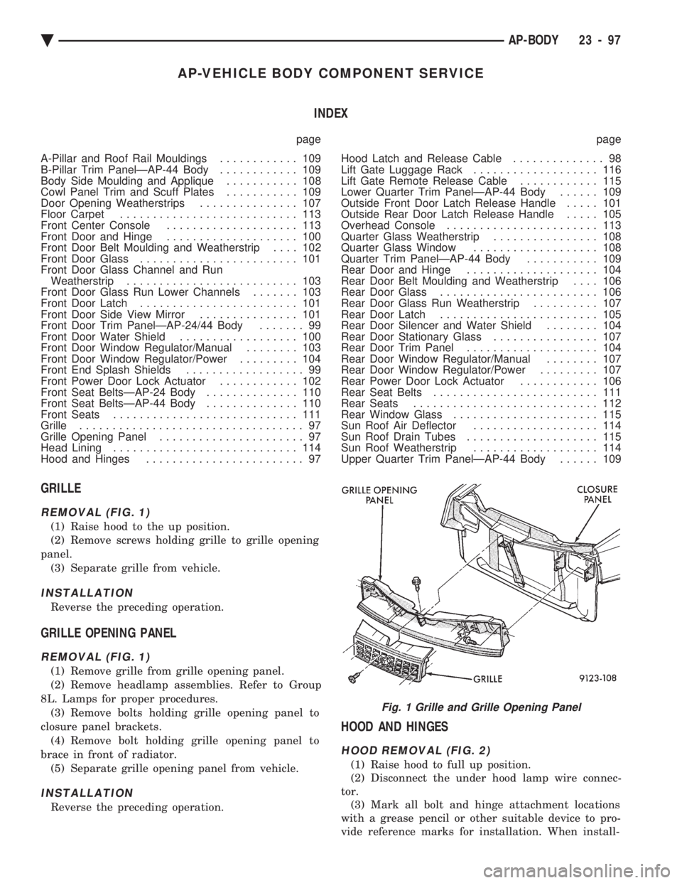
GRILLE
REMOVAL (FIG. 1)
(1) Raise hood to the up position.
(2) Remove screws holding grille to grille opening
panel. (3) Separate grille from vehicle.
INSTALLATION
Reverse the preceding operation.
GRILLE OPENING PANEL
REMOVAL (FIG. 1)
(1) Remove grille from grille opening panel.
(2) Remove headlamp assemblies. Refer to Group
8L. Lamps for proper procedures. (3) Remove bolts holding grille opening panel to
closure panel brackets. (4) Remove bolt holding grille opening panel to
brace in front of radiator. (5) Separate grille opening panel from vehicle.
INSTALLATION
Reverse the preceding operation.
HOOD AND HINGES
HOOD REMOVAL (FIG. 2)
(1) Raise hood to full up position.
(2) Disconnect the under hood lamp wire connec-
tor. (3) Mark all bolt and hinge attachment locations
with a grease pencil or other suitable device to pro-
vide reference marks for installation. When install-
Fig. 1 Grille and Grille Opening Panel
Ä AP-BODY 23 - 97
Page 2273 of 2438
AP/27-VEHICLE CONVERTIBLE BODY COMPONENT SERVICE INDEX
page page
A-Pillar and Windshield Header Weatherstrip . . . 117
Convertible Top Adjustments ............... 131
Convertible Top Header ................... 118
Convertible Top Latch Hooks ............... 131
Door Glass Alignment .................... 131
Door Glass Rear Channel ................. 127
Door Striker Guide ...................... 128
Forward Roof Rail ....................... 121
Fourth Roof Bow and Slat ................. 120
Fourth Roof Bow Slat .................... 132
Front Door Belt Moulding and Weatherstrip .... 127
Front Door Glass ........................ 125
Front Door Stationary Glass and Division Channel ............................. 126
Front Door Stationary Glass Channel Weatherstrip .......................... 126
Front Door Striker Guide Socket ............ 127
Front Seat Belt Retractor .................. 128
General Information ...................... 117
Quarter Glass and Roller Bracket ........... 132
Quarter Panel Belt Moulding ............... 129
Quarter Trim Panel ...................... 128
Rear Roof Rail ......................... 121
Rear Seat Back ......................... 128 Rear Seat Belt Retractor
.................. 129
Rear Tensioner Plate ..................... 132
Rear Window .......................... 122
Roof Linkage ........................... 121
Roof Rail Weatherstrip ................... 118
Roof Rail Weatherstrip Retainer ............. 131
Second Roof Bow and Linkage ............. 119
Sling-Well ............................. 124
Stationary Quarter Glass and Weatherstrip .... 121
Third Roof Bow ......................... 120
Top Cover ............................. 124
Top Frame ............................ 125
Top Header Trim Cover ................... 118
Top Latch ............................. 118
Top Lift Assist Cylinder ................... 122
Top Stack Down-Stop .................... 132
Top Stack Up-Stop ...................... 132
Trunk Hinge Lid ........................ 130
Trunk Lid .............................. 130
Trunk Lid Applique ...................... 130
Trunk Lid Lining ........................ 129
Trunk Opening Weatherstrip ............... 130
Windshield Header Lining ................. 117
Windshield Header Moulding ............... 117
GENERAL INFORMATION
This section will cover components that are unique
to the AP-vehicle convertible. All components that
are common to the AP-vehicle two door hardtop are
covered in the AP-Vehicle Body Components section.
WINDSHIELD HEADER MOULDING
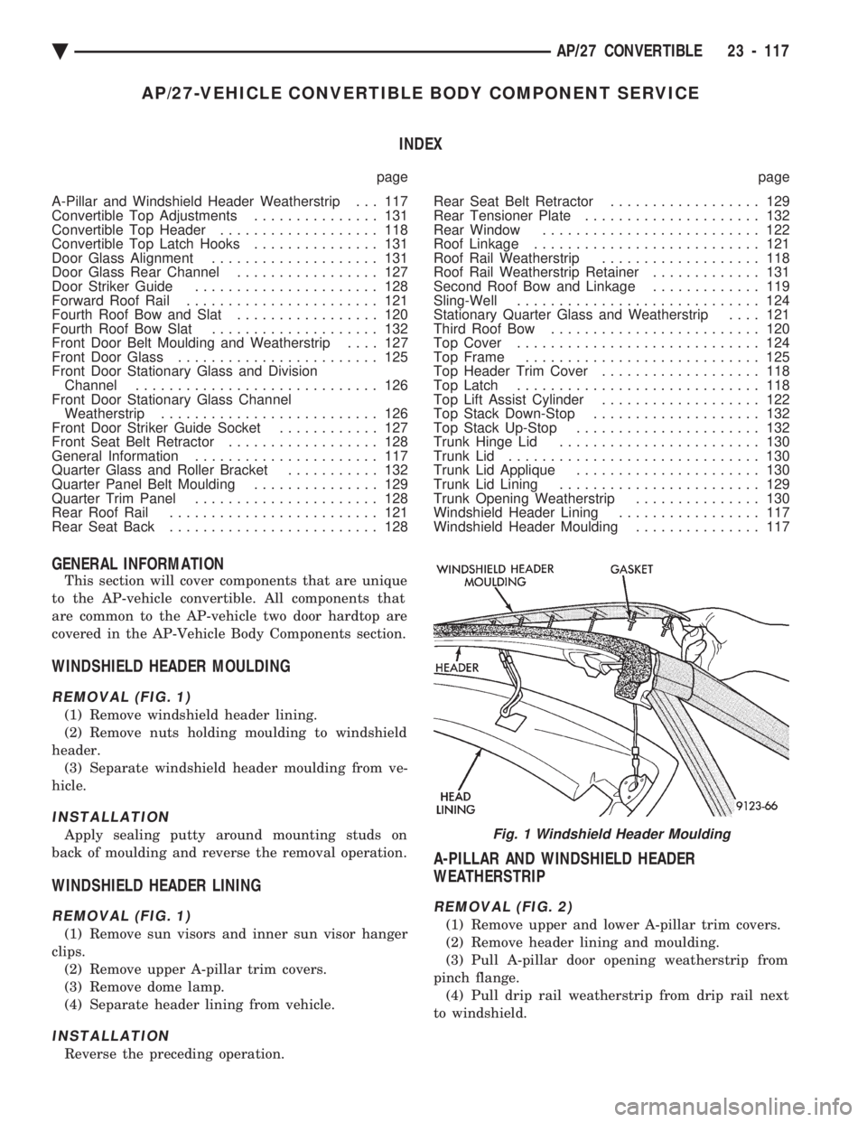
REMOVAL (FIG. 1)
(1) Remove windshield header lining.
(2) Remove nuts holding moulding to windshield
header. (3) Separate windshield header moulding from ve-
hicle.
INSTALLATION
Apply sealing putty around mounting studs on
back of moulding and reverse the removal operation.
WINDSHIELD HEADER LINING
REMOVAL (FIG. 1)
(1) Remove sun visors and inner sun visor hanger
clips. (2) Remove upper A-pillar trim covers.
(3) Remove dome lamp.
(4) Separate header lining from vehicle.
INSTALLATION
Reverse the preceding operation.
A-PILLAR AND WINDSHIELD HEADER
WEATHERSTRIP
REMOVAL (FIG. 2)
(1) Remove upper and lower A-pillar trim covers.
(2) Remove header lining and moulding.
(3) Pull A-pillar door opening weatherstrip from
pinch flange. (4) Pull drip rail weatherstrip from drip rail next
to windshield.
Fig. 1 Windshield Header Moulding
Ä AP/27 CONVERTIBLE 23 - 117
Page 2289 of 2438
AY-VEHICLE BODY COMPONENT SERVICE INDEX
page page
A-Pillar and Roof Rail Mouldings ............ 143
B-Pillar Trim Panel ...................... 143
Body Mouldings ......................... 146
Cowl Panel Trim and Scuff Plates ........... 143
Door Frame Trim Moulding ................ 137
Front Door and Hinge .................... 137
Front Door Glass ........................ 139
Front Door Latch ........................ 138
Front Door Silencer and Water Shield ........ 137
Front Door Trim Panel .................... 136
Front Door Window Regulator .............. 138
Front End Splash Shields ................. 136
Front Seat Belts ........................ 144
Front Seats ............................ 145
Grille AY/P Body ........................ 133
Grille AY/S Body ........................ 133
Grille Opening Panel AY/P Body ............ 134
Grille Opening Panel AY/S Body ............ 134
Head Lining ............................ 142
Hood and Hinges ....................... 134
Hood Latch and Release Cable ............. 135
Hood Ornament AY/P-S .................. 134
Outside Door Handle ..................... 138
Overhead Console ....................... 142 Quarter Trim Panel
...................... 143
Rear Deck Filler Panel ................... 146
Rear Door and Hinge .................... 140
Rear Door Fixed Glass Outer Cover ÐAY-S Body ......................... 141
Rear Door Fixed Window Module ........... 142
Rear Door Frame Trim Moulding ............ 139
Rear Door Glass ........................ 141
Rear Door Glass Lift Plate and Guide Bar ..... 141
Rear Door Latch ........................ 140
Rear Door Outer CoverÐAY-P Body ......... 141
Rear Door Outside Handle ................ 140
Rear Door Silencer and Water Shield ........ 140
Rear Door Trim Panel .................... 139
Rear Door Window Regulator .............. 141
Rear Seat Belts ......................... 144
Rear Seats ............................ 145
Rear Shelf Trim Panel .................... 144
Rear Window Glass ...................... 147
Side View Mirror Trim Cover ............... 137
Trunk Lid .............................. 147
Trunk Lid Hinge ........................ 147
Trunk Lid Torsion Bar .................... 148
Vinyl Roof Bonnet ....................... 146
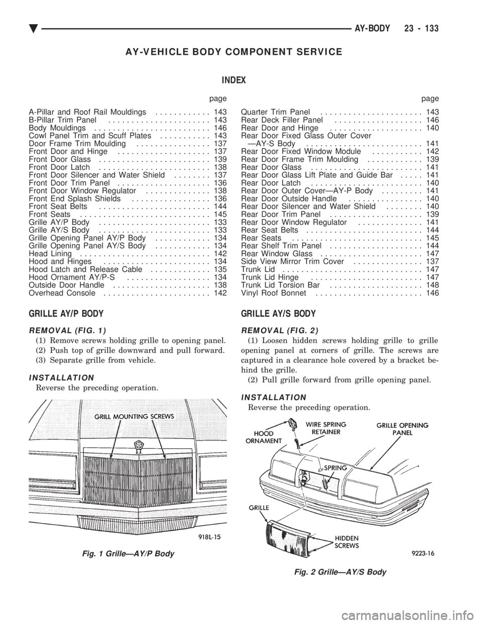
GRILLE AY/P BODY
REMOVAL (FIG. 1)
(1) Remove screws holding grille to opening panel.
(2) Push top of grille downward and pull forward.
(3) Separate grille from vehicle.
INSTALLATION
Reverse the preceding operation.
GRILLE AY/S BODY
REMOVAL (FIG. 2)
(1) Loosen hidden screws holding grille to grille
opening panel at corners of grille. The screws are
captured in a clearance hole covered by a bracket be-
hind the grille. (2) Pull grille forward from grille opening panel.
INSTALLATION
Reverse the preceding operation.
Fig. 1 GrilleÐAY/P Body
Fig. 2 GrilleÐAY/S Body
Ä AY-BODY 23 - 133
Page 2305 of 2438
HEATING AND AIR CONDITIONING
CONTENTS
page page
AUTOMATIC TEMPERATURE CONTROL (ATC) .............................. 66
COMPONENT SERVICE PROCEDURES ...... 47
FIXED DISPLACEMENT COMPRESSORÐ MODEL 10PA17 ...................... 24
FIXED DISPLACEMENT COMPRESSORÐ MODEL SD709P ...................... 38 FIXED DISPLACEMENT COMPRESSORÐ
MODEL TR105 ....................... 32
GENERAL INFORMATION .................. 1
HEATER AND A/C PERFORMANCE TESTS .... 6
REFRIGERANT SERVICE PROCEDURES ...... 8
VACUUM CONTROL SYSTEM DIAGNOSIS .... 4
VARIABLE DISPLACEMENT COMPRESSORÐ MODEL 6C17 ......................... 13
GENERAL INFORMATION INDEX
page page
A/C System Identification ................... 1
Cooling System Precautions ................. 3
Description and Operation ................... 1
Engine Cooling System Requirements .......... 2 Handling Tubing and Fittings
................. 3
Safety Precautions and Warnings ............. 3
Side Window Demisters .................... 2
System Airflow ........................... 1
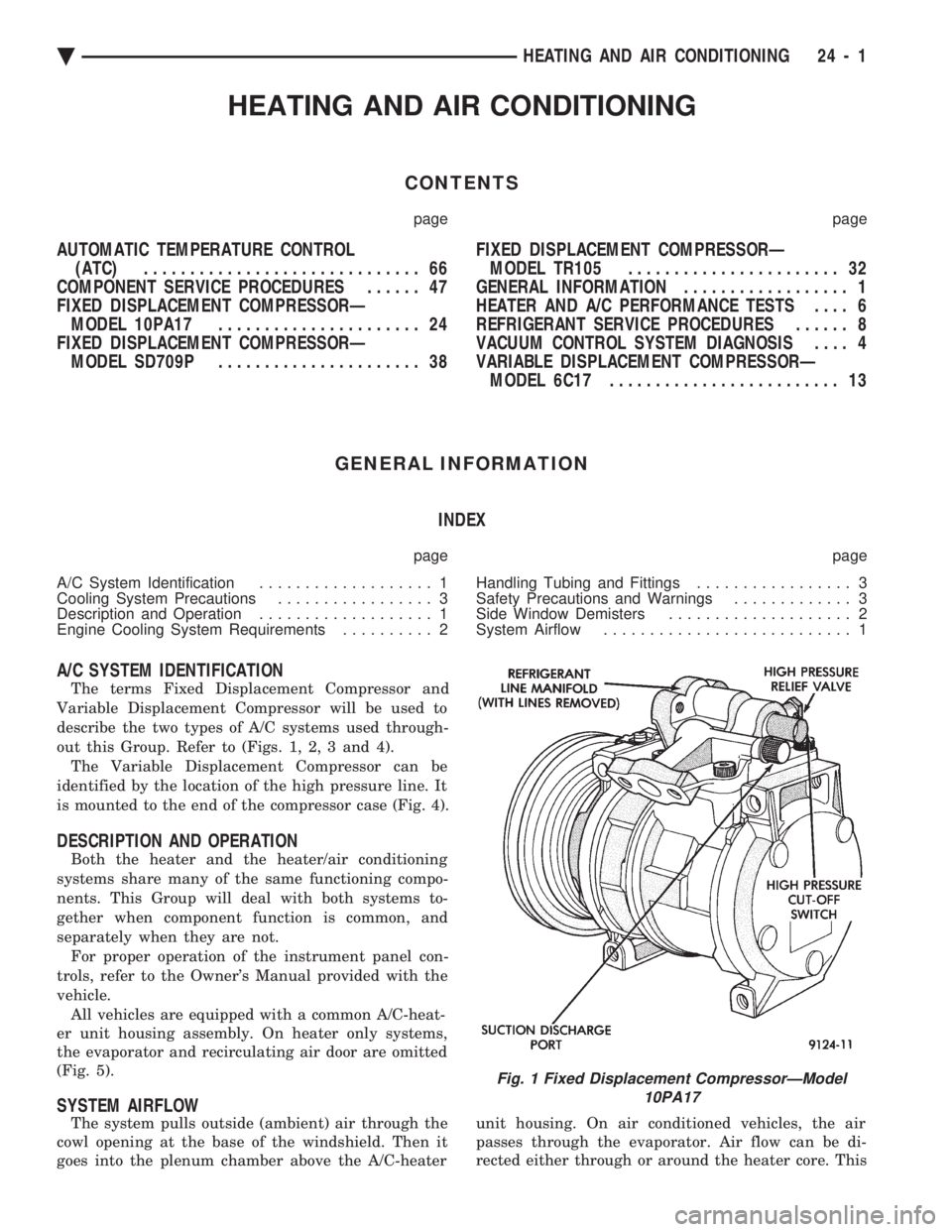
A/C SYSTEM IDENTIFICATION
The terms Fixed Displacement Compressor and
Variable Displacement Compressor will be used to
describe the two types of A/C systems used through-
out this Group. Refer to (Figs. 1, 2, 3 and 4). The Variable Displacement Compressor can be
identified by the location of the high pressure line. It
is mounted to the end of the compressor case (Fig. 4).
DESCRIPTION AND OPERATION
Both the heater and the heater/air conditioning
systems share many of the same functioning compo-
nents. This Group will deal with both systems to-
gether when component function is common, and
separately when they are not. For proper operation of the instrument panel con-
trols, refer to the Owner's Manual provided with the
vehicle. All vehicles are equipped with a common A/C-heat-
er unit housing assembly. On heater only systems,
the evaporator and recirculating air door are omitted
(Fig. 5).
SYSTEM AIRFLOW
The system pulls outside (ambient) air through the
cowl opening at the base of the windshield. Then it
goes into the plenum chamber above the A/C-heater unit housing. On air conditioned vehicles, the air
passes through the evaporator. Air flow can be di-
rected either through or around the heater core. This
Fig. 1 Fixed Displacement CompressorÐModel 10PA17
Ä HEATING AND AIR CONDITIONING 24 - 1