1993 CHEVROLET PLYMOUTH ACCLAIM Index
[x] Cancel search: IndexPage 1961 of 2438
TRANSAXLE
CONTENTS
page page
41TE FOUR SPEED AUTOMATIC TRANSAXLE . 85
41TE FOUR SPEED TRANSAXLE HYDRAULICSCHEMATICS ........................ 170
41TE ON-BOARD DIAGNOSTICS .......... 145
A-523, A-543, and A-568 MANUAL TRANSAXLE ........................... 1 SPECIFICATIONS
...................... 183
THREE SPEED TORQUEFLITE AUTOMATIC TRANSAXLE .......................... 35
THREE SPEED TRANSAXLE HYDRAULIC SCHEMATICS ........................ 162
A-523, A-543, and A-568 MANUAL TRANSAXLE INDEX
page page
Bearing Adjustment Procedure .............. 31
Differential Bearing Preload Adjustment ........ 33
Gearshift Linkage Adjustment (Cable Operated) . . 2
General Information ........................ 1 In-Car Transaxle Disassemble/Assemble
........ 4
Out of Car TransaxleÐDisassemble and Assemble . 6
Subassembly-Recondition .................. 15
Transaxle Removal and Installation ............ 5
GENERAL INFORMATION
Safety goggles should be worn at all times
when working on these transaxles. All manual
transaxles use SAE 5W-30 engine oil, meeting SG
and/or SG-CC qualifications, as the lubricant in order
to reduce wear. This 5-speed manual transaxles combine gear reduc-
tion, ratio selection, and differential functions in one
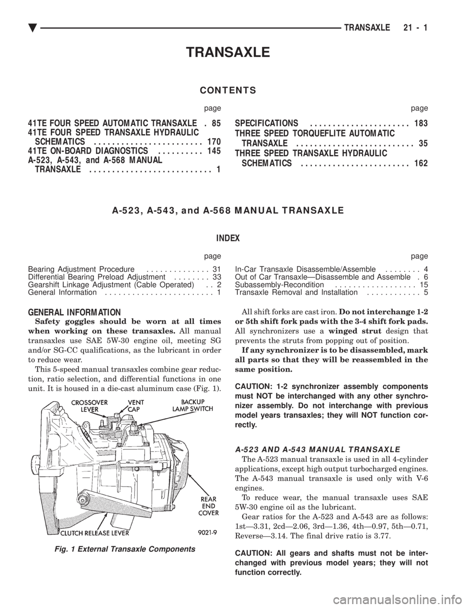
unit. It is housed in a die-cast aluminum case (Fig. 1). All shift forks are cast iron.
Do not interchange 1-2
or 5th shift fork pads with the 3-4 shift fork pads.
All synchronizers use a winged strutdesign that
prevents the struts from popping out of position. If any synchronizer is to be disassembled, mark
all parts so that they will be reassembled in the
same position.
CAUTION: 1-2 synchronizer assembly components
must NOT be interchanged with any other synchro-
nizer assembly. Do not interchange with previous
model years transaxles; they will NOT function cor-
rectly.
A-523 AND A-543 MANUAL TRANSAXLE
The A-523 manual transaxle is used in all 4-cylinder
applications, except high output turbocharged engines.
The A-543 manual transaxle is used only with V-6
engines. To reduce wear, the manual transaxle uses SAE
5W-30 engine oil as the lubricant. Gear ratios for the A-523 and A-543 are as follows:
1stÐ3.31, 2cdÐ2.06, 3rdÐ1.36, 4thÐ0.97, 5thÐ0.71,
ReverseÐ3.14. The final drive ratio is 3.77.
CAUTION: All gears and shafts must not be inter-
changed with previous model years; they will not
function correctly.
Fig. 1 External Transaxle Components
Ä TRANSAXLE 21 - 1
Page 1995 of 2438
THREE SPEED TORQUEFLITE AUTOMATIC TRANSAXLE INDEX
page page
Accumulator-Recondition ................... 67
Aluminum Thread Repair ................... 48
Assembly Subassembly Installation ........... 57
Band Adjustment ......................... 47
Bearing Adjustment Procedures .............. 81
Clutch and Servo Air Pressure Tests .......... 43
Differential Repair ........................ 76
Disassembly Subassembly Removal .......... 50
Fluid and Filter Change .................... 40
Fluid Drain and Refill ..................... 40
Fluid Leakage-Transaxle Torque Converter Housing Area .......................... 44
Fluid Level and Condition .................. 40
Front Clutch-Recondition ................... 62
Front Planetary & Annulus Gear-Recondition .... 65
Gearshift Linkage Adjustment ............... 46
General Information ....................... 35
Governor ............................... 48
Hydraulic Control Pressure Adjustments ....... 47
Hydraulic Pressure Tests ................... 42
Kickdown Servo (Controlled Load)-Recondition . . 67 Low/Reverse Servo-Recondition
.............. 66
Oil Cooler Flow Check .................... 48
Oil Coolers and Tubes Reverse Flushing ...... 48
Oil Pump-Recondition ..................... 62
Output Shaft Repair ...................... 71
Park/Neutral Position and Back-Up Lamp Switch . 47
Parking Pawl ............................ 71
Pump Oil Seal-Replacement ................ 61
Rear Clutch-Recondition ................... 64
Road Test .............................. 40
Selection of Lubricant ..................... 40
Special Additives ......................... 40
Three Speed Torqueflite General Diagnosis ..... 36
Throttle Pressure Linkage Adjustment ......... 46
Torque Converter Clutch Solenoid Wiring Connector ............................ 40
Transaxle and Torque Converter Removal ...... 48
Transfer Shaft Repair ..................... 68
Valve Body-Recondition .................... 57
Vehicle Speed Sensor Pinion Gear ........... 47
GENERAL INFORMATION
Safety goggles should be worn at all times
when working on these transaxles. This transaxle combines a fully automatic 3 speed
transmission, final drive gearing, and differential into
a front wheel drive system. The unit is a Metric
design. The identification markings and usage of the
transaxle are charted in Diagnosis and Tests. Transaxle operation requirements are differ-
ent for each vehicle and engine combination and
some internal parts will be different to provide
for this. Therefore, when replacing parts, refer to
the seven digit part number stamped on rear of
the transaxle oil pan flange. Within this transaxle, there are 3 primary areas:
(1) Main center line plus valve body.
(2) Transfer shaft center line (includes governor and
parking sprag). (3) Differential center line. Center distances be-
tween the main rotating parts in these 3 areas are held
precise. This maintains a low noise level through
smooth accurate mesh of the gears. The torque converter, transaxle area, and differential
are housed in an integral aluminum die casting. The
differential oil sump is common with thetransaxle
sump. Separate filling of the differential is NOT nec-
essary. The torque converter is attached to the crankshaft
through a flexible driving plate. Cooling of the con-
verter is accomplished by circulating the transaxle
fluid through an oil-to-water type cooler located in the
radiator side tank and/or an oil-to air heat ex- changer. The torque converter assembly is a sealed
unit that cannot be disassembled.
The transaxle fluid is filtered by an internal filter
attached to the lower side of the valve body assem-
bly. Engine torque is transmitted to the torque con-
verter then, through the input shaft to multiple-disc
clutches in the transaxle. The power flow depends on
the application of the clutches and bands. Refer to
Elements in Use Chart in Diagnosis and Tests sec-
tion. The transaxle consists of two multiple-disc
clutches, an overrunning clutch, two servos, a hy-
draulic accumulator, two bands, and two planetary
gear sets. They provide three forward ratios and a re-
verse ratio. The common sun gear of the planetary
gear sets is connected to the front clutch by a driving
shell. The drive shell is splined to the sun gear and
to the front clutch retainer. The hydraulic system
consists of an oil pump, and a single valve body
which contains all of the valves except the governor
valves. The transaxle sump and differential sump are
both vented through the dipstick.Output torque
from the main center line is delivered through heli-
cal gears to the transfer shaft.This gear set is a
factor of the final drive (axle) ratio. The shaft also
carries the governor and parking sprag. An integral
helical gear on the transfer shaft drives the differen-
tial ring gear. The final drive gearing is completed
with one of three gear sets producing overall top gear
ratios of 2.78, 3.02, or 3.22 depending on model and
application.
Ä TRANSAXLE 21 - 35
Page 2045 of 2438
41TE FOUR SPEED AUTOMATIC TRANSAXLE INDEX
page page
41TE Transaxle General Diagnosis ........... 88
Aluminum Thread Repair ................... 98
Bearing Adjustment Procedure .............. 141
Clutch Air Pressure Tests .................. 95
Coolers and Tubes Reverse Flushing ......... 98
Diagnosis Chart ``B'' ....................... 90
Diagnosis Trouble Code Chart ``A'' ............ 89
Differential Repair ....................... 136
Fluid and Filter Changes ................... 93
Fluid Drain and Refill ..................... 93
Fluid Leakage-Torque Converter Housing Area . . 97
Fluid Level and Condition .................. 93
Gearshift Linkage Adjustment ............... 98
General Information ....................... 85
Hydraulic Pressure Tests ................... 94
Input Clutches-Recondition ................ 121
Oil Cooler Flow Check .................... 99 Oil Pump Seal Replace
................... 136
Park/Neutral Position Switch ............... 102
Pinion Factor Procedure .................. 104
Road Test .............................. 93
Selection of Lubricant ..................... 93
Solenoid Assembly-Replace ................ 101
Special Additives ......................... 93
Speed Sensor-Input ...................... 102
Speed Sensor-Output .................... 103
Torque Converter Clutch Break-In Procedure . . . 104
Transaxle Quick Learn Procedure ........... 103
Transaxle Recondition .................... 105
Transaxle Removal and Installation ........... 99
Transmission Control Module ............... 103
Transmission Range Switch ................ 102
Valve Body-Recondition ................... 132
GENERAL INFORMATION
The 41TE four-speed FWD transaxle uses fully-
adaptive controls. Adaptive controls are those which
perform their functions based on real-time feedback
sensor information. The transaxle uses hydraulically
applied clutches to shift a planetary gear train.
TRANSAXLE IDENTIFICATION
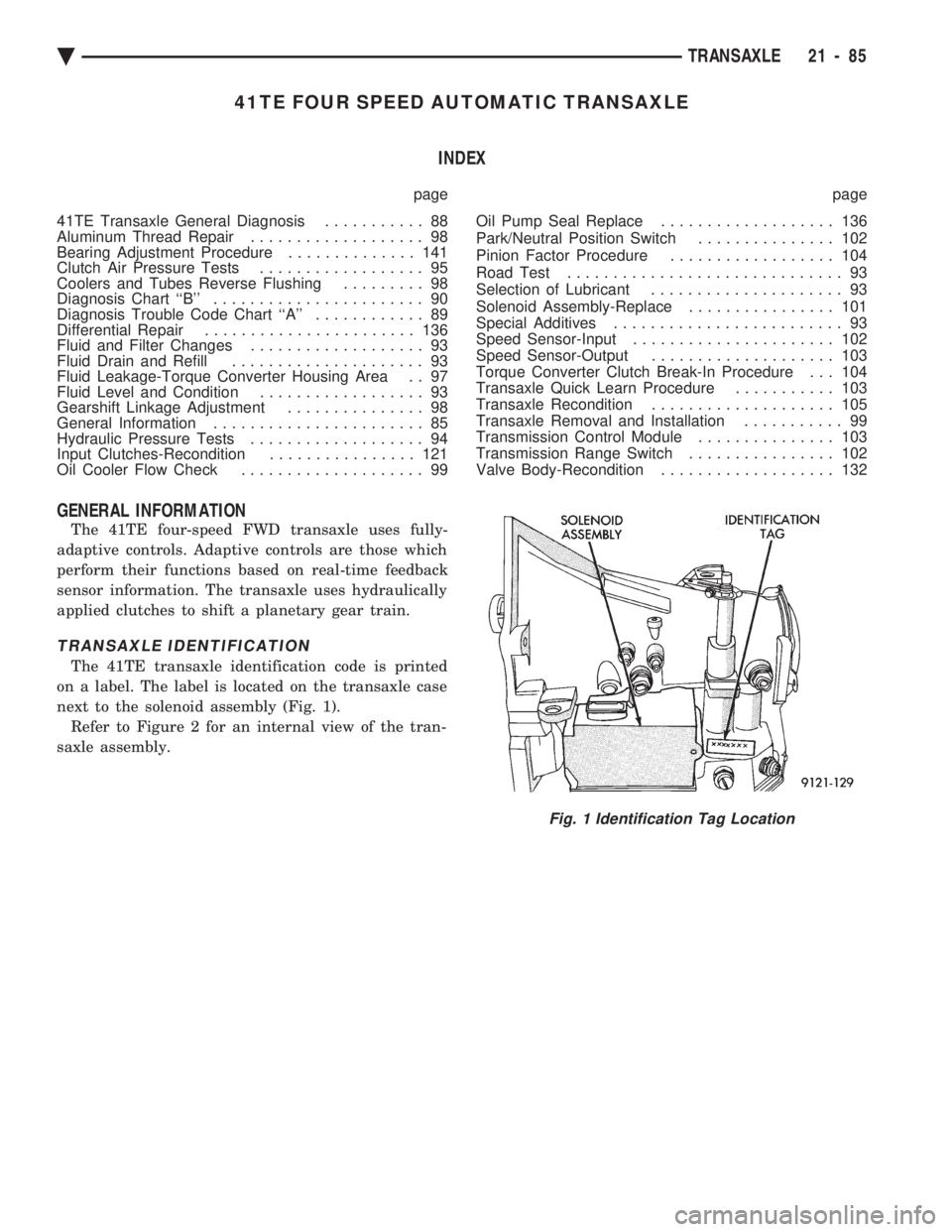
The 41TE transaxle identification code is printed
on a label. The label is located on the transaxle case
next to the solenoid assembly (Fig. 1). Refer to Figure 2 for an internal view of the tran-
saxle assembly.
Fig. 1 Identification Tag Location
Ä TRANSAXLE 21 - 85
Page 2070 of 2438
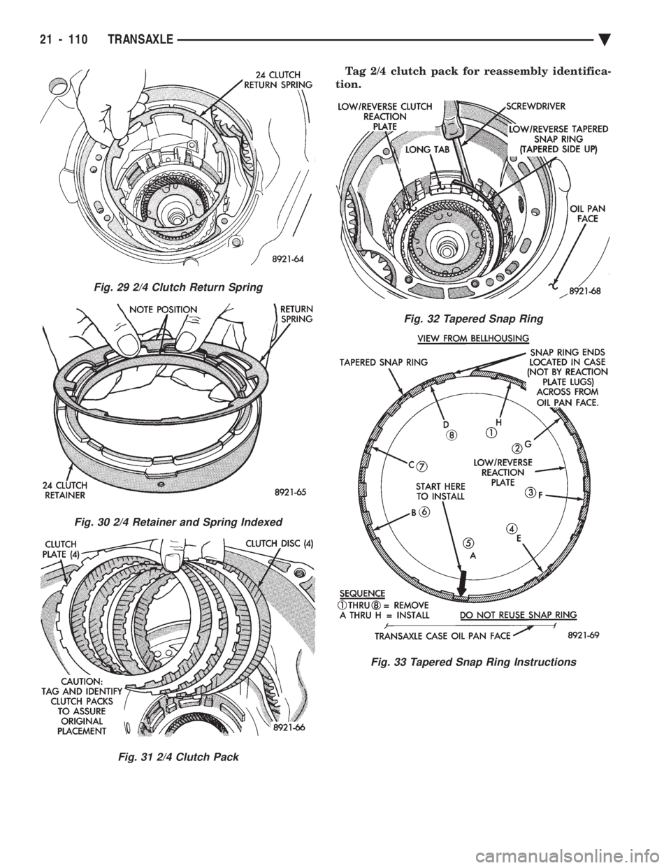
Tag 2/4 clutch pack for reassembly identifica-
tion.
Fig. 29 2/4 Clutch Return Spring
Fig. 30 2/4 Retainer and Spring Indexed
Fig. 31 2/4 Clutch Pack
Fig. 32 Tapered Snap Ring
Fig. 33 Tapered Snap Ring Instructions
21 - 110 TRANSAXLE Ä
Page 2105 of 2438
41TE ON-BOARD DIAGNOSTICS INDEX
page page
CCD Bus .............................. 145
Diagnostic Trouble Code Charts ............ 146
Diagnostic Trouble Codes ................. 145
DRB II Scan Tool ....................... 146 General Information
...................... 145
Limp-In Mode .......................... 145
On-Board Diagnostics Information ........... 145
GENERAL INFORMATION
The information in this manual is designed to help
the technician understand and repair the transaxle
with the aid of the built in on-board diagnostics. Chrysler Corporation has developed a com-
plete set of diagnostic manuals which cover the
diagnosis of the 41TE transaxle. They have been
designed to make transaxle diagnosis accurate
and simple. Use these manuals with the DRB II
scan tool and the latest cartridge, when diagnos-
ing transaxle problems.
ON-BOARD DIAGNOSTICS INFORMATION
The 41TE transaxle is controlled and monitored by
the transmission control module. The transmission
control module monitors critical input and output
circuits within the transaxle. Some circuits are tested continuously; others are
checked only under certain conditions. Each circuit
monitored by the transmission control module has a
corresponding fault message assigned to it that can be
read with the DRB II scan tool. If the on-board diagnostic system senses that one of
the circuits is malfunctioning, the corresponding code
is stored in memory. If the malfunction goes away after
the code is stored, the transmission control module will
erase the code after 75 key cycles.
CCD BUS
In order to diagnose the 41TE transaxle, diagnostic
trouble codes in the transmission control module's
memory should be read. Use the Diagnostic Readout
Box (DRB II) scan tool to read codes. If more than one
diagnostic trouble code exists, diagnostic priority
should be given to the most recent code. With CCD bus
bias and communication problems, the DRB II scan
tool displays an appropriate message. Diagnostic
trouble codes might not be accessible until the bus
problem is fixed. The following is a list of probable
causes for a bus problem:
² Open or short to ground/battery in either or both
CCD bus wires (pins 4 and 43).
² Open or short to ground/battery in either or both
41TE transaxle's bias wires (pin 5 and 44) on vehicles
requiring the transaxle to bias the bus.
² Open or short to ground/battery in the diagnostic
connector bus wire. ²
Internal failure of any module connected to the bus.
The CCD bus should have 2.5 volts (+2.5 volts on
CCD+ and -2.5 volts on CCD-). The bus error message displayed by the DRB II scan
tool should be helpful in diagnosing the CCD bus. For more information on diagnosing CCD bus prob-
lems, refer to the 1993 Diagnostic Procedures Manual
(non-communication with the CCD bus). All other
problems refer to the 1993 Body Vehicle Communica-
tions Diagnostic Procedures Manual.
DIAGNOSTIC TROUBLE CODES
Diagnostic Trouble Codes are two-digit numbers that
identify which circuit is malfunctioning. A code can be
set for hydraulic and mechanical reasons as well as for
electrical problems. In most cases, codes do not pin-
point which specific component is defective. Diagnostic trouble codes can only be read with
the use of the DRB II scan tool or equivalent.
HARD FAULTS
Any Diagnostic trouble code that comes back within
3 engine starts (reset count 3 or less) is a ``Hard Fault''.
This means that the defect is there every time the
transmission control module checks that circuit.
SOFT FAULTS
A ``Soft Fault'' is one that occurs intermittently. It is
not there every time the transmission control module
checks the circuit. Most soft faults are caused by wiring
or connector problems. Intermittent defects must be
looked for under the specific conditions that caused
them.
LIMP-IN MODE
The transmission control module continuously
checks for electrical and internal transaxle problems.
When a problem is sensed, the transmission control
module stores a diagnostic trouble code. All but twelve
of these codes cause the transaxle to go into the
``Limp-in mode''. While in this mode, electrical power is
taken away from the transaxle. When this happens,
the only transaxle ranges that will function are:
Ä TRANSAXLE 21 - 145
Page 2149 of 2438
WHEELSÐTIRES
CONTENTS
page page
SPECIFICATIONS ........................ 8
TIRE SERVICE PROCEDURES .............. 1 WHEELS SERVICE PROCEDURES
........... 6
TIRE SERVICE PROCEDURES INDEX
page page
Cleaning of Tires .......................... 1
General Information ........................ 1
Pressure Gauges ......................... 2
Radial-Ply Tires ........................... 1
Repairing Leaks .......................... 3
Rotation ................................ 3 Spare TireÐCompact
...................... 1
Tire Inflation Pressures ..................... 2
Tire Noise or Vibration ..................... 3
Tire Wear Patterns ........................ 3
Tread Wear Indicators ...................... 3
GENERAL INFORMATION
Throughout this group, references may be made to a
particular vehicle by letter or number designation. A
chart showing the breakdown of these designations is
included in the Introduction Section. Tires are designed for the vehicle and provide the
best overall performance for normal operation. The
ride and handling characteristics match the vehicle's
requirements. With proper care they will give excellent
reliability traction, skid resistance and tread life. They
have load carrying capacity, when properly inflated, to
operate at loads up to the specified Maximum Vehicle
Capacity. Driving habits have more effect on tire life than any
other factor. Careful drivers will obtain, in most cases,
much greater mileage than severe or careless drivers. A
few of the driving habits which will shorten the life of
any tire are:
² Rapid acceleration and deceleration
² Severe application of brakes
² High-speed driving
² Taking turns at excessive speeds
² Striking curbs and other obstacles
Radial ply tires can be more susceptible to irregular
tread wear. It is very important to follow the tire
rotation interval shown in the section on Tire
Rotation to achieve a greater tread life potential.
RADIAL-PLY TIRES
Radial-ply tires improve handling, tread life, and
ride quality and decrease rolling resistance. Radial-ply tires must always be used in sets of four
and under no circumstances should they be used on
the front only. However, they may be mixed with temporary spare tires when necessary,
but reduced speeds are recommended. Radial-ply tires have the same load carrying capac-
ity as other types of tires of the same size. They also
use the same recommended inflation pressures.
SPARE TIREÐCOMPACT
The compact spare tire is designed for emergency
use only. The original tire should be repaired and re-
installed at the first opportunity. Refer to Owner's
Manual for complete details.
TIRE CHAINS
Tire snow chains may be used on certainmodels.
Refer to Owner's Manual for more information.
CLEANING OF TIRES
Remove protective coating on tires before delivery
of vehicle, otherwise it could cause deterioration of
tires. Remove protective coating by applying warm wa-
ter, letting it soak one minute, and then scrubbing
the coating away with a soft bristle brush. Steam cleaning may also be used for cleaning.
DO NOT use gasoline or wire brush for cleaning.
DO NOT use mineral oil or an oil-based solvent.
Ä WHEELSÐTIRES 22 - 1
Page 2154 of 2438
WHEELS SERVICE PROCEDURES INDEX
page page
General Information ........................ 6
Tire and Wheel Balance .................... 6
Tire and Wheel Run Out .................... 7 Wheel Installation
......................... 6
Wheel Replacement ....................... 6
GENERAL INFORMATION
Original equipment wheels are designed for proper
operation at all loads up to the maximum vehicle ca-
pacity. All models use steel or cast aluminum drop center
wheels. The safety rim wheel (Fig. 1) has raised sec-
tions between the rim flanges and the rim well A.
Initial inflation of the tires forces the bead over
these raised sections. In case of tire failure the raised
sections help hold the tire in position on the wheel
until the vehicle can be brought to a safe stop. Cast aluminum wheels require special balance
weights and alignment equipment.
WHEEL INSTALLATION
The wheel studs and nuts are designed for specific
applications and must be replaced with equivalent
parts. Do not use replacement parts of lessor quality
or a substitute design. All aluminum and some steel
wheels have wheel stud nuts which feature an en-
larged nose. This enlarged nose is necessary to en-
sure proper retention of the aluminum wheels. Before installing the wheel, be sure to remove any
build up of corrosion on the wheel mounting surfaces
with scraping and wire brushing. Installing wheels
without good metal-to-metal contact could cause later
loosening of wheel nuts. This could adversely affect
the safety and handling of your vehicle. To install the wheel, position it properly on the
mounting surface using the hub pilot as a guide. All wheel nuts should be lightly tightened before progres-
sively tightening them in sequence (Fig. 2). Tighten
wheel nuts to 129 N Im (95 ft. lbs.). Never use oil or
grease on studs or nuts.
WHEEL REPLACEMENT
Wheels must be replaced if they:
² have excessive run out
² are bent or dented
² leak air through welds
² have damaged bolt holes
Wheel repairs employing hammering, heating, or
welding are not allowed. Original equipment replacement wheels are avail-
able through your dealer. When obtaining wheels from
any other source, the replacement wheels should be
equivalent in load carrying capacity. The wheel dimen-
sions (diameter, width, offset, and mounting configura-
tion) must match original equipment wheels. Failure to
use equivalent replacement wheels may adversely af-
fect the safety and handling of your vehicle. Replace-
ment with used wheels is not recommended as
their service history may have included severe
treatment or very high mileage and they could
fail without warning.
TIRE AND WHEEL BALANCE
Balancing need is indicated by vibration of seats,
floor pan, or steering wheel when driving over 90 km/h
(55 mph) on a smooth road.
Fig. 1 Safety Rim
Fig. 2 Tightening Wheel Nuts (5-Stud)
22 - 6 WHEELSÐTIRES Ä
Page 2158 of 2438
BODY DIAGNOSTIC PROCEDURES INDEX
page page
Water Leaks ............................. 2 Wind Noise.............................. 3
WATER LEAKS
Water leaks can be caused by poor sealing, improper
body component alignment, body seam porosity, miss-
ing plugs, or blocked drain holes. Centrifugal and
gravitational force can cause water to drip from an
area somewhat distant from the actual leak point,
making leak detection difficult. All body sealing points
should be water tight in normal wet driving conditions.
Water flowing downward from the front of the vehicle
should not enter the passenger or luggage compart-
ment. Moving sealing surfaces will not always seal
water tight under all conditions. At times, side glass,
door, or convertible top seals will allow water to enter
the passenger compartment during high pressure
washing or hard driving rain (severe) conditions. Over
compensating on door, glass, or top adjustments to stop
a water leak that occurs under severe conditions, can
cause premature seal wear and excessive closing or
latching effort. After a repair procedure has been
performed, water test vehicle to verify leak has stopped
before returning vehicle to use.
VISUAL INSPECTION BEFORE WATER LEAK TESTS
Verify that floor and body plugs are in place, body
drains are clear and body components are aligned and
sealed. If component alignment or sealing is necessary,
refer to the appropriate section of this group for proper
procedures.
WATER LEAK TESTS
WARNING: DO NOT USE ELECTRIC SHOP LIGHTS
OR TOOLS IN WATER TEST AREA, PERSONAL IN-
JURY CAN RESULT.
When a determination has been made on the condi-
tions that a water leak occurs, simulate the conditions
as closely as possible.
² If a leak occurs when the car is parked in a steady
light rain, flood the leak area with a open ended garden
hose.
² If a leak occurs at highway speeds in a steady rain,
test the leak area with a stream or fan spray of water
from a garden hose with an adjustable nozzle. Direct
the spray in the direction comparable to actual condi-
tions. ²
If a leak seems to occur only when the vehicle is
parked on an incline, hoist the end or side of the vehicle
to simulate this condition before water testing. This
method can also be used when the leak occurs when the
vehicle accelerates, stops, or turns. If the leak occurs
on acceleration, hoist the front of the vehicle. If the
leak occurs when braking, hoist the back of the vehicle.
If the leak occurs on left turns, hoist the left side of the
vehicle. If the leak occurs on right turns, hoist the right
side of the vehicle. For hoisting recommendations refer
to Group 0, Lubrication and Maintenance, General
Information section.
WATER LEAK DETECTION
To detect a water leak point of entry, perform a water
test and watch for water tracks or droplets forming on
the inside if the vehicle. If necessary remove interior
trim covers or panels to gain visual access to the leak
area. If the hose can not be positioned without being
held, have someone help perform the water test. Some water leaks must be tested for a considerable
length of time to become apparent. When a leak ap-
pears, determine the highest point of the water track or
drop. The highest point usually will indicate the point
of entry. After leak point has been determined, repair
the leak and water test to verify that leak has stopped. Locating the entry point of water that is leaking into
a cavity between panels can be difficult. The trapped
water splashes or runs from the cavity it is dammed up
in, often at a distance from the entry point. Most water
leaks of this type become apparent after accelerating,
stopping, turning, or when on a incline.
MIRROR INSPECTION METHOD
When a leak point area is visually obstructed, use a
suitable mirror to gain visual access. A mirror can also
be used to deflect light to a limited access area to assist
in locating a leak point.
BRIGHT LIGHT LEAK TEST METHOD
Some water leaks in the luggage compartment can be
detected without water testing. Position the vehicle in
a brightly light area. From inside the darkened lug-
gage compartment inspect around seals and body
seams. If necessary, have a helper direct a drop light
over the suspected leak areas around the lug-
23 - 2 BODY Ä