1993 CHEVROLET PLYMOUTH ACCLAIM wiring diagram
[x] Cancel search: wiring diagramPage 29 of 2438

FOREWORD
The information contained in this Service Manual has been prepared for the professional automotive
technician involved in daily repair operations. Information describing the operation and use of standard and
optional equipment is included in the Owner's Manual provided with the vehicle.
These diagrams contain the latest information at the time of publication and incorporate the wiring schematic
for the basic vehicle and available optional equipment.
The diagrams are grouped by body type and sales division. The body codes are explained in the General
Information section. (ExampleÐAP-D, P=Shadow, Sundance). To locate a system or component refer to the black
index tabs on the next page. The tab will assist you in locating the desired area of the manual.
An alphabetical index is provided at the beginning of each section to help you in locating a system or
component. All diagrams are identified by SHEET NUMBER which is found in the lower right- or left-hand corner
of the page.
A Service Manual Comment form is included at the rear of this manual. Use the form to provide Chrysler
Corporation with your comments and suggestions.
Chrysler Corporation reserves the right to change testing procedures, specifications, diagnosis, repair
methods, or vehicle wiring at any time without prior notice or incurring obligation.
NOTE: The acronyms, terminology and nomenclature used to identify emissions related components in this
manual may have changed from prior publications. These new terms are in compliance with S.A.E.
recommended practice J1930. This terminology standard (J1930) is required to comply with the 1993
California Air Research Board (CARB) requirements.
FOR INFORMATION NOT CONTAINED IN THIS MANUAL, REFER TO THE FRONT WHEEL
DRIVE PASSENGER VEHICLES ENGINEÐCHASSISÐBODY OR ELECTRICALÐFUELÐEMISSIONS
SERVICE MANUALS.
NEXT PAGE ©
Page 30 of 2438

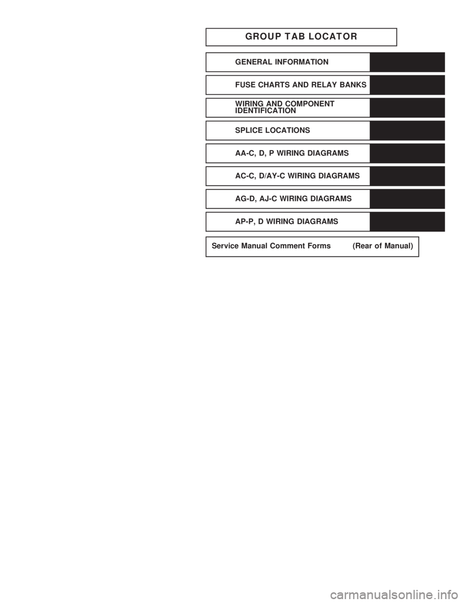
GROUP TAB LOCATOR
GENERAL INFORMATION
FUSE CHARTS AND RELAY BANKS
WIRING AND COMPONENT
IDENTIFICATION
SPLICE LOCATIONS
AA-C, D, P WIRING DIAGRAMS
AC-C, D/AY-C WIRING DIAGRAMS
AG-D, AJ-C WIRING DIAGRAMS
AP-P, D WIRING DIAGRAMS
Service Manual Comment Forms (Rear of Manual)
Page 36 of 2438

BLEEDING BENDIX ANTILOCK 4 BRAKE SYSTEM......5-3
BASE BRAKE SYSTEM BLEEDING PROCEDURE.........5-3
MASTER CYLINDER FLUID LEVEL................5-3
TESTING FOR FLUID CONTAMINATION.............5-4 WIRING DIAGRAMS AA-BODY
..................8W-1
INDEX...............................8W-1
WIRING DIAGRAMS AJ BODY ..................8W-8
ALPHABETICAL INDEX.....................8W-8
Page 137 of 2438

(2) Check all connectors for correct assembly. Check
all connectors for incorrectly installed termi-
nals. (3) Check pin #21 for minimum of 9.5 volts.
(4) Check pin #20 for minimum of 9.5 volts (with
ignition key on). (5) Check voltage at pins #5 and #16. The measure-
ment should exceed 0 volts. (6) Check pin #19 for continuity.
(7) The engine speed should exceed 680 rpm during
idle. All doors and trunk must be closed for the
system to function.
DIAGNOSTICS PROCEDURES
(1) Use the D.R.B. II tester and the 1991 air suspen-
sion diagnostic service cartridge to begin the trouble-
shooting process. (2) Use the D.R.B. mating connector under the dash
(drivers side) to plug-in the D.R.B. II test connector
(Fig. 10). (3) The tester will conduct a complete check of the
suspension system status. (4) The tester will list the steps to follow to access
and diagnose the failure. (5) A Volt/Ohm meter can be used for some diagnos-
tic testing.
HEIGHT SENSOR CHECK
If a sensor signal/signals are missing. Follow the
repair procedure listed below. (1) Check ground circuit continuity. (Remember
front and rear grounds are on different circuits. (2) For front ground circuit continuity check circuit
S 33. (3) For rear ground circuit continuity check circuit
X20. (4) Refer to control module pin out chart and wiring
diagram (see Group 8F in wiring diagram manual) for
individual circuit details. (5) If open circuits are not found replace the compo-
nent. Complete circuit testing and connector assem-
blies before replacing a strut or right rear shock. (6) To measure resistance values, see Height Sensor
Logic Chart and Initial Diagnostic Check in System
Operation.
HEIGHT SENSOR LOGIC CHART
Ä SUSPENSION AND DRIVESHAFTS 2 - 79
Page 228 of 2438

pared by the (CAB) and used to detect brake system
faults that would require Anti -Lock Braking to be
disabled.The Boost Pressure Transducer is mounted on the
bottom of the hydraulic assembly, (Fig. 1) and moni-
tors booster servo pressure. The Primary Pressure
Transducer is mounted on the left side of the hydrau-
lic assembly and monitors primary master cylinder
pressure.
DIFFERENTIAL PRESSURE SWITCH
A non-latching Differential Pressure Switch is used
to detect a pressure difference greater than 2,068
kPa (300 psi.) between the primary and secondary
master cylinder hydraulic circuits. If detected, the
Differential Pressure Switch grounds the output of
the primary pressure transducer (circuit B-218). This
results in a 0.0 volt signal from the Primary Pres-
sure Transducer that is sensed by the (CAB) as a dif-
ferential pressure fault. The (CAB) will then light
the Red Brake Warning Lamp and the Amber Anti-
Lock Warning Lamp and disable the Anti-Lock brak-
ing function. See Fig. 1 for location of the differential
pressure switch.
PROPORTIONING VALVES
The ABS system uses screw-in Proportioning
Valves in place of the conventional Height Sensing Proportioning Valve. Each rear brake circuit has its
own screw-in Proportioning Valve that is attached to
the rear brake outlet ports of the hydraulic assembly
(Fig. 1). These valves limit brake pressure to the
rear brakes after a certain brake pressure is reached.
This improves front to rear wheel brake balance dur-
ing normal braking.
FILTERS-SERVICEABILITY
There is a screen filter in each of the two master
cylinder fill ports. There is also a low pressure filter
for the pump/motor. The filter is integral to the
Pump/Motor low pressure hose.
FLUID LEVEL SWITCH
A Low Fluid Switch is located in the hydraulic as-
sembly fluid reservoir, (Fig. 1). The switch consists of
a float and magnetic reed switch that closes when
low fluid is detected. The Low Fluid Switch is used
as an input, to the Red Brake Warning Lamp, the
(CAB), and the EVIC (if so equipped). When a low
fluid condition exists the switch will close, grounding
the low fluid circuit and illuminating the Red Brake
Warning Lamp. The (CAB) will disable the Anti-
Lock Function and light the Amber Anti-Lock Warn-
ing Lamp if vehicle is in motion above 3 mph. If
vehicle is not in motion, the Amber Anti-Lock Warn-
ing Lamp will NOT be lit.
DUAL FUNCTION PRESSURE SWITCH WIRING DIAGRAM
5 - 78 ANTI-LOCK 10 BRAKE SYSTEM Ä
Page 306 of 2438

ANTILOCK WARNING LAMP DIODE
The Warning Lamp Relay on the Bendix Antilock
4 Brake System has been replaced with a diode. The
diode is used to control the function of the warning
lamp and is located inside the CAB module wiring
harness. The diode is a replaceable component of the
wiring harness, and will not require replacement of
the entire wiring harness if only the diode is diag-
nosed to have failed. When the system relay is de-energized, the Anti-
lock warning lamp will be lit. This will occur because
a ground path exists for the Antilock warning lamp
through the Antilock warning lamp diode and the
system relay armature. When the system relay is en-
ergized by the CAB, the system relay armature will
no longer provide a ground and the lamp will turn
off. Thus, the lamp will be lit if either the CAB is
disconnected or a system fault causes the Antilock to
be turned off.
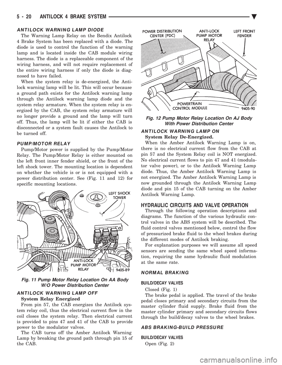
PUMP/MOTOR RELAY
Pump/Motor power is supplied by the Pump/Motor
Relay. The Pump/Motor Relay is either mounted on
the left front inner fender shield, or the front of the
left shock tower. The mounting location is dependent
on whether the vehicle is or is not equipped with a
power distribution center. See (Fig. 11 and 12) for
specific mounting locations.
ANTILOCK WARNING LAMP OFF
System Relay Energized
From pin 57, the CAB energizes the Antilock sys-
tem relay coil, thus the electrical current flow in the
coil closes the system relay. Then electrical current
is provided to pins 47 and 41 of the CAB to provide
power to the modulator valves. The CAB turns off the Amber Antilock Warning
Lamp by breaking the ground path through pin 15 of
the CAB.
ANTILOCK WARNING LAMP ON
System Relay De-Energized.
When the Amber Antilock Warning Lamp is on,
there is no electrical current flow from the CAB at
pin 57 and the System Relay coil is NOT energized.
No electrical current flows to pin 47 and 41 (modula-
tor valve power), or to the Antilock Warning Lamp
diode. Thus, the Amber Antilock Warning Lamp is
not energized. The Amber Antilock Warning Lamp is
now grounded through the Antilock Warning Lamp
diode and pin 15 of the CAB turning on the Amber
Antilock Warning Lamp.
HYDRAULIC CIRCUITS AND VALVE OPERATION
Through the following operation descriptions and
diagrams. The function of the various hydraulic con-
trol valves in the ABS system will be described. The
fluid control valves mentioned below, control the flow
of pressurized brake fluid to the wheel brakes during
the different modes of Antilock braking. For explanation purposes we will assume all speed
sensors are sending the same wheel speed informa-
tion, requiring the same hydraulic fluid modulation
at the same rate.
NORMAL BRAKING
BUILD/DECAY VALVES
Closed (Fig. 1)
The brake pedal is applied. The travel of the brake
pedal closes primary and secondary circuits from the
master cylinder fluid supply. Brake fluid from the
master cylinder primary and secondary circuits flows
through the build/decay valves to the wheel brakes.
ABS BRAKING-BUILD PRESSURE
BUILD/DECAY VALVES
Open (Fig. 2)
Fig. 11 Pump Motor Relay Location On AA Body W/O Power Distribution Center
Fig. 12 Pump Motor Relay Location On AJ BodyWith Power Distribution Center
5 - 20 ANTILOCK 4 BRAKE SYSTEM Ä
Page 363 of 2438

RADIATOR HOSES
The hoses are removed using Constant Tension
Clamp pliers to compress hose clamp. A hardened, cracked, swollen or restricted hose
should be replaced. Do not damage radiator inlet and
outlet when loosening hoses. Radiator hoses should be routed without any kinks
and indexed as designed. The use of molded hoses is
recommended. Spring type hose clamps are used in all applica-
tions. If replacement is necessary replace with the
original style spring type clamp.
FANS
All models use electric motor driven cooling system
fans. The fan modules include a motor support which
may (depending on model) include a shroud. The
module is fastened to the radiator by screws with
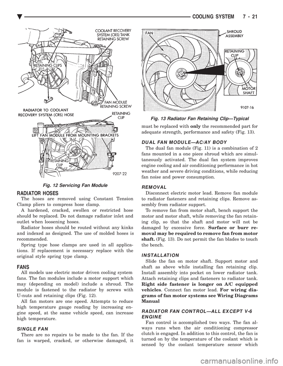
U-nuts and retaining clips (Fig. 12). All fan motors are one speed. Attempts to reduce
high temperature gauge reading by increasing en-
gine speed, at the same vehicle speed, can increase
high temperature.
SINGLE FAN
There are no repairs to be made to the fan. If the
fan is warped, cracked, or otherwise damaged, it must be replaced with
onlythe recommended part for
adequate strength, performance and safety (Fig. 13).
DUAL FAN MODULEÐAC/AY BODY
The dual fan module (Fig. 11) is a combination of 2
fans mounted in a one piece shroud which are simul-
taneously activated. The dual fan system improves
engine cooling and air conditioning performance in hot
weather and severe driving conditions, while reducing
fan noise and power consumption.
REMOVAL
Disconnect electric motor lead. Remove fan module
to radiator fasteners and retaining clips. Remove as-
sembly from radiator support. To remove fan from motor shaft, bench support the
motor and motor shaft, while removing the fan retain-
ing clip, so that the shaft and motor will not be
damaged by excessive force. Surface or burr re-
moval may be required to remove fan from motor
shaft. (Fig. 13). Do not permit the fan blades to touch
the bench.
INSTALLATION
Slide the fan on motor shaft. Support motor and
shaft as above while installing fan retaining clip.
Install assembly into pocket on lower radiator tank.
Attach retaining clips and fasteners to radiator tank.
Right side fastener is longer on A/C equipped
vehicles . Connect fan motor lead. For wiring dia-
grams of fan motor systems see Wiring Diagrams
Manual
RADIATOR FAN CONTROLÐALL EXCEPT V-6 ENGINE
Fan control is accomplished two ways. The fan al-
ways runs when the air conditioning compressor
clutch is engaged. In addition to this control, the fan is
turned on by the temperature of the coolant which is
sensed by the coolant temperature sensor which
Fig. 12 Servicing Fan Module
Fig. 13 Radiator Fan Retaining ClipÐTypical
Ä COOLING SYSTEM 7 - 21
Page 364 of 2438

sends the message to the Engine Controller. The En-
gine Controller turns on the fan through the fan re-
lay. See Wiring Diagrams Manual for circuity and
diagnostics provided.Switching through the Engine Controller provides
fan control for the following conditions.
² The fan will not run during cranking until the en-
gine starts no matter what the coolant temperature
is.
² Fan will run when the air conditioning clutch is
engaged and low pressure cutout switch is closed.
² For 4 cylinder application the fan will run at ve-
hicle speeds above about 40 mph only if coolant tem-
perature reaches 110ÉC (230ÉF). It will turn off when
the temperature drops to 104ÉC (220ÉF). At speeds
below 40 mph the fan switches on at 102ÉC (215ÉF)
and off at 93ÉC (200ÉF).
² This is to help prevent steaming. The fan will run
only below 16ÉC (60ÉF) ambient. Between 38ÉC
(100ÉF) to 97ÉC (195ÉF) coolant temperature, at idle
and then only for three minutes.
RADIATOR FAN CONTROLÐAC/AY BODY V-6 ONLY
For this application, fan control is accomplished
based on coolant temperature, and on A/C head pres-
sure. These vehicles receive the variable displace-
ment compressor. The fan will go on when;
² Coolant temperature reaches 102ÉC (215ÉF) and off
at 93.4ÉC (200ÉF) regardless of vehicle speed.
² When the head pressure reaches 1516.9 kPa (220
psi) and turn off when the pressure reaches 1103 kPa
(160 psi).
TEMPERATURE GAUGE INDICATION
At idle the temperature gauge will rise slowly to
about 5/8 gauge travel. The fan will come on and the
gauge will drop to about 1/2 gauge travel, this is nor-
mal.
ELECTRIC FAN MOTOR
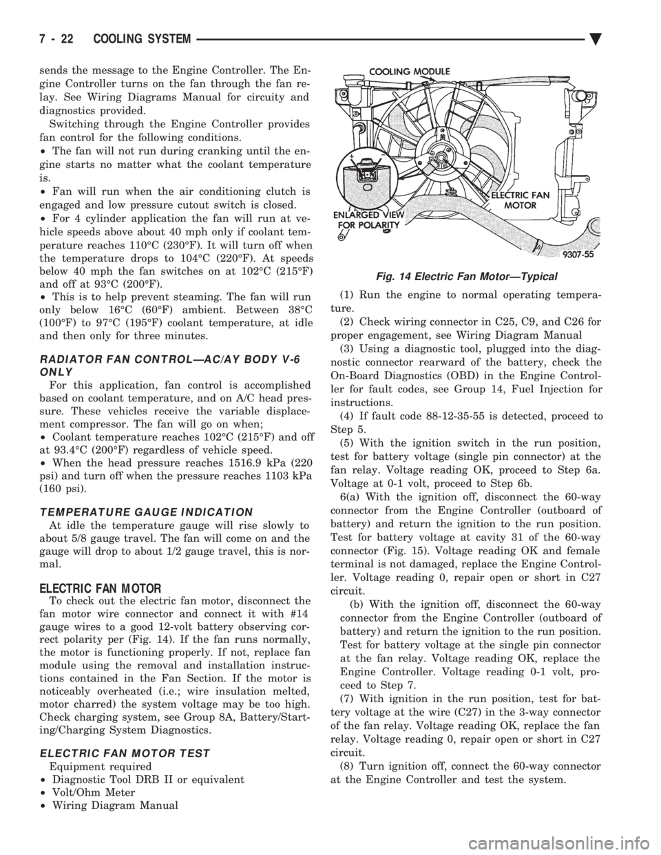
To check out the electric fan motor, disconnect the
fan motor wire connector and connect it with #14
gauge wires to a good 12-volt battery observing cor-
rect polarity per (Fig. 14). If the fan runs normally,
the motor is functioning properly. If not, replace fan
module using the removal and installation instruc-
tions contained in the Fan Section. If the motor is
noticeably overheated (i.e.; wire insulation melted,
motor charred) the system voltage may be too high.
Check charging system, see Group 8A, Battery/Start-
ing/Charging System Diagnostics.
ELECTRIC FAN MOTOR TEST
Equipment required
² Diagnostic Tool DRB II or equivalent
² Volt/Ohm Meter
² Wiring Diagram Manual (1) Run the engine to normal operating tempera-
ture. (2) Check wiring connector in C25, C9, and C26 for
proper engagement, see Wiring Diagram Manual (3) Using a diagnostic tool, plugged into the diag-
nostic connector rearward of the battery, check the
On-Board Diagnostics (OBD) in the Engine Control-
ler for fault codes, see Group 14, Fuel Injection for
instructions. (4) If fault code 88-12-35-55 is detected, proceed to
Step 5. (5) With the ignition switch in the run position,
test for battery voltage (single pin connector) at the
fan relay. Voltage reading OK, proceed to Step 6a.
Voltage at 0-1 volt, proceed to Step 6b. 6(a) With the ignition off, disconnect the 60-way
connector from the Engine Controller (outboard of
battery) and return the ignition to the run position.
Test for battery voltage at cavity 31 of the 60-way
connector (Fig. 15). Voltage reading OK and female
terminal is not damaged, replace the Engine Control-
ler. Voltage reading 0, repair open or short in C27
circuit. (b) With the ignition off, disconnect the 60-way
connector from the Engine Controller (outboard of
battery) and return the ignition to the run position.
Test for battery voltage at the single pin connector
at the fan relay. Voltage reading OK, replace the
Engine Controller. Voltage reading 0-1 volt, pro-
ceed to Step 7.
(7) With ignition in the run position, test for bat-
tery voltage at the wire (C27) in the 3-way connector
of the fan relay. Voltage reading OK, replace the fan
relay. Voltage reading 0, repair open or short in C27
circuit. (8) Turn ignition off, connect the 60-way connector
at the Engine Controller and test the system.
Fig. 14 Electric Fan MotorÐTypical
7 - 22 COOLING SYSTEM Ä